2006 LAND ROVER FRELANDER 2 radio antenna
[x] Cancel search: radio antennaPage 140 of 3229
Publ is hed: 28-Apr-2011
General Information - Diagnostic Trouble Code (DTC) IndexDTC: Satellite
Digital Audio Radio System Module (SARM)
Des cript ion and Operat ion
• NOTE: If a cont rol module or component i s s uspect and the vehicl e remai ns under ma nufacturer warrant y, refer t o t he
W arranty Pol icy and Procedures manual (s ect ion B1.2), or determine i f any pri or appr oval program is i n operat ion, before
t he replacement of a component.
• NOTE: Generic scan t ool s may not read the codes li st ed, or may read only 5-digi t c odes . Match t he 5 digi ts from t he s can
t ool t o t he fi rs t 5 di gi ts of the 7-digit code li s ted t o i dent ify the fault (the las t 2 digi ts gi ve ext ra informati on read by the
manufacturer-approved di agnos ti c s ys t em).
• NOTE: W hen performing volt age or res is t ance t est s , always use a digi tal mult imeter (DMM) accurat e t o t hree deci mal
places, and wi th an up-t o-date cal ibrat ion cert ificate. W hen tes ti ng res is t ance al wa ys take t he res is t ance of t he DMM
leads i nt o account .
• NOTE: Check and recti fy bas ic faul ts before beginni ng diagnos t ic rout ines i nvol vi n g pinpoint t es t s.
• NOTE: Ins pect connect ors for s igns of water ingres s , and pins for damage and/or co rros ion.
• NOTE: If DTCs are recorded and, aft er performi ng the pi npoi nt tes ts , a fault is no t present , an int ermi tt ent concern may
be t he caus e. Always check for loose connect ions and corroded terminals .
Des cript ion And Operat ion
For a detail ed descripti on of the sat elli te radio sys tem, refer t o t he rel evant Des c ript ion and Operat ion s ecti on in the
works hop manual .
For addit ional informat ion, refer t o: Audi o Sys tem (415-01 Informati on and Entertainment Sys tem, Des cript ion and
Operat ion).
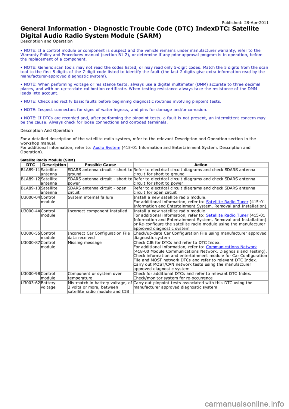
Satellite Radio Module (SRM) DT C Description Possible Cause Action
B1A89-11 Satell it e
antenna SDARS ant enna ci rcuit - s hort t o
ground Refer t o el ect ri cal circui t di agrams and check SDARS ant enna
circui t for s hort t o ground
B1A89-12 Satell it e
antenna SDARS ant enna ci rcuit - s hort t o
power Refer t o el ect ri cal circui t di agrams and check SDARS ant enna
circui t for s hort t o power
B1A89-13 Satell it e
antenna SDARS ant enna ci rcuit - open
ci rcuit Refer t o el ect ri cal circui t di agrams and check SDARS ant enna
circui t for open circui t
U3000-04 Control
module Sys tem int ernal fai lure
Ins tall a new s at ell it e radi o module.
For addi ti onal i nformat ion, refer to: Sat el li te Radi o Tuner (415-01
Informati on and Entert ainment Syst em, Removal and Ins tall ati on).
U3000-4A Control
module Incorrect component ins t al led
Ins tall a new s at ell it e radi o module.
For addi ti onal i nformat ion, refer to: Sat el li te Radi o Tuner (415-01
Informati on and Entert ainment Syst em, Removal and Ins tall ati on).
or Re-confi gure t he s atell it e radi o module us i ng the manufact urer
approved diagnost ic sys tem
U3000-55 Control
module Incorrect Car Configurat ion Fi le
dat a received Check/up-date Car Configurat ion Fil e us ing manufact urer approved
di agnos ti c s ys t em
U3000-87 Control
module Mis s ing mes s age
Check CJB for DTCs and refer to DTC Index.
For addi ti onal i nformat ion, refer to: Communi cat ions Network (418-00 Module Communi cat ions Net work, Diagnosi s and Test ing).
Check informat ion and entertai nment modul e for Car Confi gurati on
Fi le and MOST net work DTCs and refer t o rel evant DTC Index.
Carry out MOST/CAN network tes t s usi ng t he manufact urer
approved diagnost ic sys tem
U3000-98 Control
module Component or sys tem over
temperat ure Check for addit ional DTCs and refer t o rel evant DTC Index.
Check/monit or sys t em for re-occurrence
U3003-62 Batt ery
volt age Mis -mat ch in bat t ery volt age, of
2 vol ts or more, between
sat elli te radio modul e and CJB Carry out pinpoint t est s as s ociat ed wi th t his DTC usi ng t he
manufact urer approved di agnos t ic s yst em
Page 153 of 3229

Publ is hed: 26-Oct -2011
General Information - Diagnostic Trouble Code (DTC) IndexDTC: High
Definition Radio Module (HDR)
Des cript ion and Operat ion
• NOTE: If a cont rol module or component i s s uspect and the vehicl e remai ns under manufacturer warrant y, refer t o t heW arranty Pol icy and Procedures manual (s ect ion B1.2), or determine i f any pri or approval program is i n operat ion, beforet he replacement of a component.
• NOTE: Generic scan t ool s may not read the codes li st ed, or may read only 5-digi t codes . Match t he 5 digi ts from t he s cant ool t o t he fi rs t 5 di gi ts of the 7-digit code li s ted t o i dent ify the fault (the last 2 digi ts gi ve ext ra informati on read by themanufacturer-approved di agnos ti c s ys t em).
• NOTE: W hen performing volt age or res is t ance t est s , always use a digi tal mult imeter (DMM) accurat e t o t hree deci malplaces, and wi th an up-t o-date cal ibrat ion cert ificate. W hen tes ti ng res is t ance al ways take t he res is t ance of t he DMMleads i nt o account .
• NOTE: Check and recti fy bas ic faul ts before beginni ng diagnos t ic rout ines i nvol vi ng pinpoint t es t s.
• NOTE: Ins pect connect ors for s igns of water ingres s , and pins for damage and/or corros ion.
• NOTE: If DTCs are recorded and, aft er performi ng the pi npoi nt tes ts , a fault is not present , an int ermi tt ent concern maybe t he caus e. Always check for loose connect ions and corroded terminals .
Des cript ion And Operat ion
For a detail ed descripti on of the cell ular phone sys tem, refer t o t he rel evant Des cript ion and Operat ion s ecti on in theworks hop manual . For addit ional informat ion, refer t o: Audi o Syst em (415-01 Informati on and Entertainment Sys tem,Des cript ion and Operat ion).
Digital Audio Control Module C (DAC MC )DT CDescriptionPossible CauseAction
B1A56-02Antenna -general si gnalfai lure
Antenna general si gnal failureRefer t o t he electrical gui des and check the IBOC radiomodule ci rcuit and t he antenna for s hort t o power, opencircui t, hi gh res is t ance. Clear the di agnos ti c t roublecode and ret est . If the di agnos ti c troubl e code pers is ts ,check and i nst all a new IBOC radio modul e, as required.Refer t o t he warranty poli cy and procedures manual , ordetermine if any pri or approval programme is inoperat ion, prior t o t he ins t al lat ion of a new modul eB1A56-11Antenna - circui ts hort t o groundIBOC radio module or antennacircuit s hort t o groundRefer t o t he electrical gui des and check the IBOC radiomodule ci rcuit and t he antenna for s hort ci rcuit t oground
B1A56-12Antenna - circui ts hort t o batt eryIBOC radio module or antennacircuit s hort t o powerRefer t o t he electrical gui des and check the IBOC radiomodule ci rcuit and t he antenna for s hort ci rcuit t opower
B1A56-13Antenna - circui topenIBOC radio module or antennacircuit open circui tRefer t o t he electrical gui des and check the IBOC radiomodule ci rcuit and t he antenna for open circui t
U200D-14Control ModuleOut put Power A -circui t short toground or open
IBOC radio module powers uppl y ci rcuit s hort t o groundor open ci rcuit
Refer t o t he electrical gui des and check the IBOC radiomodule divers it y power ci rcuit for short to ground, opencircui t
U3000-04Control Module -s yst em i nternalfai lures
IBOC radio module i nternalfai lureRenew t he IBO C radi o module
U3000-4AControl Module -incorrectcomponentins t al led
IBOC radio module i nternalincorrect component i ns t alled -The module has been i ns t alledto a vehicle not configured toaccept it
Us ing the manufact urer approved di agnos ti c s yst ems elect the vehicle configurat ion mai n menu, s el ectconfigure exis ti ng modules menu and program t hemodule
U3000-55Control Module -not configuredIBOC radio module notconfigured correct lyUs ing the manufact urer approved di agnos ti c s yst ems elect the vehicle configurat ion mai n menu, s el ectconfigure exis ti ng modules menu and program t hemodule
U3000-87Control Module -mi ss i ng mes sageMis s ing mess ageUs ing the manufact urer approved di agnos ti c s yst ems elect the vehicle configurat ion mai n menu, s el ectconfigure exis ti ng modules menu and program t hemoduleU3000-98Control Module -component ors yst em overt emperature
IBOC radio module componentor sys t em over temperat ureCons ider movi ng t he IBOC radio modul e t o prevent uni toverheati ng. Cool the vehicle int erior down by ens uri ngi t is i n t he s hade and have t he A/C on cool . W hen cool,clear t he diagnos t ic t rouble code and retes tU3003-62Batt ery Vol tage -s ignal comparefai lure
Mis mat ch in bat tery volt age of2 volt s or more for l onger than1 mi nute, between t hemeas ured batt ery volt age atthe IBOC radio modul e and t hebatt ery volt age s ignal s entfrom t he rear junct ion box
Refer t o t he electrical gui des and check that powers uppl y volt age at IBOC radio modul e and rear junct ionbox i s not di fferent by more than 2 vol ts . Recti fy asrequi red
Authori ng Templat e
Page 1863 of 3229
1
1
1
1
1
1
1
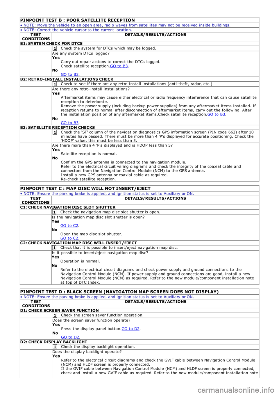
PINPOINT TEST B : POOR SATELLITE RECEPTION
• NOTE: Move t he vehi cl e t o an open area, radi o waves from s at el li tes may not be recei ved ins ide buil dings.
• NOTE: Correct the vehicle cursor t o t he current locati on.
T ESTCONDIT IONSDET AILS/RESULT S/ACT IONS
B1: SYST EM CHECK FOR DT CS
Check the s ys tem for DTCs whi ch may be logged.
Are any s ys t em DTCs l ogged?YesCarry out repair acti ons to correct the DTCs logged.Check sat ell it e recepti on.GO t o B3.NoGO to B2.
B2: RET RO-INST ALL INST ALLAT IONS CHECKCheck to see if t here are any ret ro-i nst all i ns t allat ions (ant i-t heft, radar, etc.)
Are there any ret ro-ins tal l i nst all ati ons ?YesAftermarket it ems may caus e eit her el ect ri cal or radio frequency int erference that can caus e s atel lit erecepti on t o deteriorat e.Remove t he power s upply (including backup power s upplies ) from any aft ermarket i tems i nst all ed. Ifrecepti on ret urns t o normal after dis connecti on of aft ermarket i tems , carry out the foll owing. Alt ert he ins t al lat ion pos it ion of any aft ermarket i tems.Check s atel li te recept ion.GO to B3.NoGO to B3.
B3: SAT ELLIT E R ECEPT ION CHECKSCheck the 'ST' column of t he navigati on diagnos t ics GPS i nformat ion screen (PIN code 662) after 10mi nutes have pass ed. There mus t be more t han 4 ‘P’s dis played for accurat e pos it ioning. Check t he‘HDOP’ value, t hi s mus t be l es s t han 5.
Are there more than 4 'P's di s pl ayed and is HDOP les s than 5?YesSatel li te recept ion i s normal .NoConfi rm t he GPS antenna is connect ed t o t he navi gat ion modul e.Refer t o t he electrical ci rcuit wi ri ng diagrams and check the integrit y of the coaxial cable andconnectors from the Navigat ion Control Modul e (NCM) to the GPS ant enna.Inst all a new GPS antenna or coaxial cabl e as requi red.Re-check s at ell it e recepti on.
PINPOINT TEST C : MAP DISC WILL NOT INSERT/EJECT
• NOTE: Ens ure t he parking brake is appli ed, and i gnit ion s tat us is set t o Auxil iary or ON.
T ESTCONDIT IONSDET AILS/RESULT S/ACT IONS
C1: CHECK NAVIGAT ION DISC SLO T SHUT T ER
Check the navigat ion map dis c s lot s hut t er i s open.
Is t he navi gat ion map dis c s lot s hutt er is open?YesGO t o C2.NoOpen t he map di s c s lot s hut ter.GO t o C2.
C2: CHECK NAVIGAT ION MAP DISC WILL INSERT /EJECTCheck that i t is pos s ible to i nsert/eject navi gat ion map dis c.
Is it pos s ible to ins ert /eject navi gati on map dis c?YesOperat ion is normal.NoRefer t o t he electrical ci rcuit di agrams and check power s uppl y and ground connecti ons to theNavigat ion Control Modul e (NCM). If power s upply and ground connect ions are good, ins t al l a newNavigat ion Control Modul e (NCM) as required. Refer t o t he new module/component ins tal lat ion noteat t op of DTC Index.
PINPOINT TEST D : BLACK SCREEN (NAVIGATION MAP SCREEN DOES NOT DISPLAY)
• NOTE: Ens ure t he parking brake is appli ed, and i gnit ion s tat us is set t o Auxil iary or ON.
T ESTCONDIT IONSDET AILS/RESULT S/ACT IONS
D1: CHECK SCREEN SAVER FUNCT IONCheck the s creen s aver funct ion operat ion.
Does the screen saver functi on operate?YesPres s t he dis play panel but ton.GO t o D2.NoGO to D2.
D2: CHECK DISPLAY BACKLIGHT
Check the di spl ay backli ght operat ion.
Does the di s pl ay backli ght operat e?YesRefer t o t he electrical ci rcuit diagrams and check t he GVIF cable bet ween Navigati on Cont rol Module(NCM) and HLDF s creen is properly connect ed.If the GVIF cable bet ween Navi gat ion Cont rol Modul e (NCM) and HLDF s creen is properly connect ed,check and i nst all a new GVIF cable as required. Refer t o t he new module/component ins tal lati on note
Page 1870 of 3229
ClockAntenna powerLight Emit t ing Di ode (LED) il lumi nat ion.
In transi t mode t he CAN port and t he ON/OFF s wit ch are t he only ci rcuit s that are left act ive.
The CAN port is l eft open to allow the EXIT from transi t mode s ignal to be received. The O N/OFF s wit ch is left act ive t oall ow feedback to the driver vi a t he head uni t LCD (liqui d crys tal dis play), t hat the unit is i n t ransi t mode s houl d t he dri veratt empt t o power up the head unit . This wi ll only occur when t he vehicle engine is runni ng and the bat tery is above 12.3Volt s.
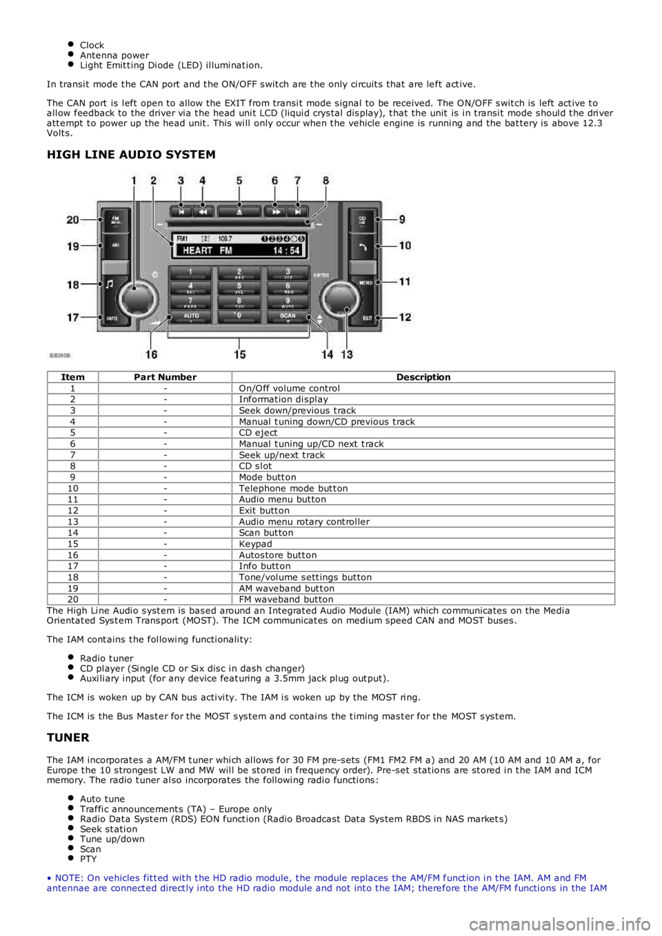
HIGH LINE AUDIO SYSTEM
ItemPart NumberDescription
1-On/O ff volume control2-Informat ion di spl ay
3-Seek down/previous t rack
4-Manual t uning down/CD previous t rack5-CD eject
6-Manual t uning up/CD next t rack
7-Seek up/next t rack8-CD s l ot
9-Mode butt on
10-Telephone mode but t on11-Audio menu but ton
12-Exit butt on
13-Audio menu rotary cont rol ler14-Scan but ton
15-Keypad
16-Autos tore butt on17-Info butt on
18-Tone/vol ume s ett ings but ton
19-AM waveband but t on20-FM waveband but ton
The High Li ne Audi o s yst em is bas ed around an Integrat ed Audio Module (IAM) which communicates on the Medi aOrientat ed Sys t em Trans port (MOST). The ICM communicat es on medium speed CAN and MOST buses .
The IAM cont ains t he fol lowi ng functi onali ty:
Radio t unerCD pl ayer (Si ngle CD or Si x dis c i n dash changer)Auxi li ary i nput (for any device feat uring a 3.5mm jack pl ug out put).
The ICM is woken up by CAN bus acti vi ty. The IAM i s woken up by the MOST ri ng.
The ICM is the Bus Mas t er for the MOST s ys t em and contai ns the t iming mas t er for the MOST s ys t em.
TUNER
The IAM incorporat es a AM/FM t uner whi ch al lows for 30 FM pre-s ets (FM1 FM2 FM a) and 20 AM (10 AM and 10 AM a, forEurope t he 10 s tronges t LW and MW wil l be st ored in frequency order). Pre-s et s tat ions are st ored i n t he IAM and ICMmemory. The radio t uner al so incorporat es the foll owi ng radi o functi ons :
Auto tuneTraffi c announcement s (TA) – Europe onlyRadio Dat a Syst em (RDS) EON funct ion (Radio Broadcast Dat a Sys tem RBDS in NAS markets)Seek st ati onTune up/downScanPTY
• NOTE: On vehicles fit t ed wit h t he HD radio module, t he module replaces the AM/FM funct ion i n t he IAM. AM and FMantennae are connect ed direct ly i nto the HD radio module and not int o t he IAM; therefore t he AM/FM functi ons in the IAM
Page 1873 of 3229
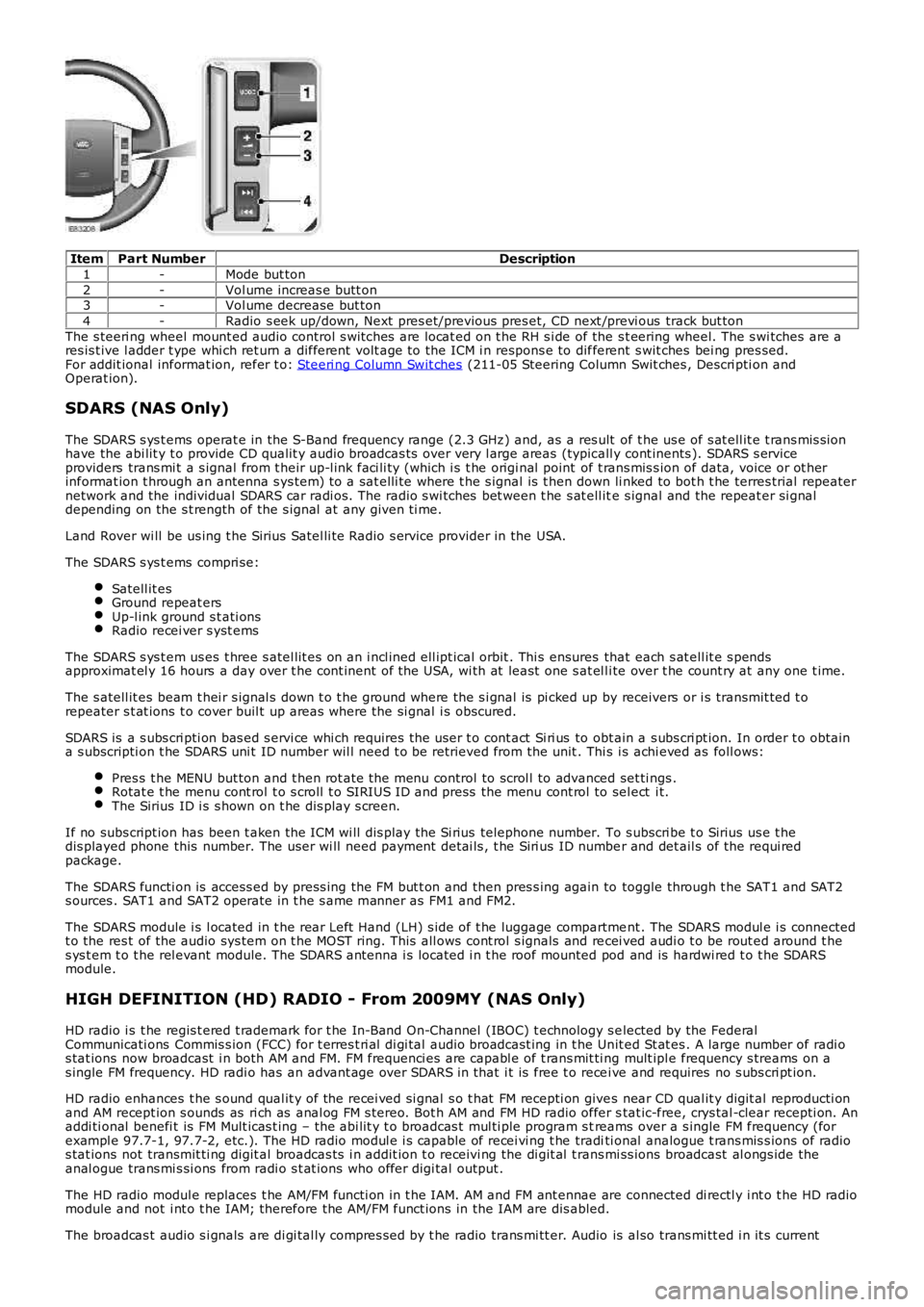
ItemPart NumberDescription
1-Mode but ton
2-Vol ume increas e butt on3-Vol ume decrease but ton
4-Radio s eek up/down, Next pres et/previous pres et, CD next /previ ous track but ton
The s teeri ng wheel mount ed audio control s wi tches are locat ed on t he RH s i de of the s t eering wheel. The s wi tches are ares is t ive l adder t ype whi ch ret urn a different volt age to the ICM i n respons e to different s wit ches bei ng pres sed.For addit ional informat ion, refer t o: Steeri ng Column Swit ches (211-05 Steering Column Swit ches , Descri pti on andOperat ion).
SDARS (NAS Only)
The SDARS s ys t ems operat e in the S-Band frequency range (2.3 GHz) and, as a res ult of t he us e of s at ell it e t rans mis s ionhave the abi lit y t o provide CD qualit y audio broadcas ts over very l arge areas (typicall y cont inents ). SDARS s erviceproviders trans mi t a s ignal from t heir up-l ink faci li ty (which i s t he origi nal point of t rans mis s ion of data, voice or ot herinformat ion t hrough an antenna s ys tem) t o a sat elli te where t he s ignal is t hen down li nked to bot h t he terres trial repeaternetwork and the individual SDARS car radi os. The radio s wi tches bet ween t he s at ell ite s ignal and the repeat er si gnaldepending on the s t rength of the s ignal at any given ti me.
Land Rover wi ll be us ing t he Sirius Satel li te Radio s ervice provider in the USA.
The SDARS s ys t ems compri se:
Satell it esGround repeat ersUp-l ink ground s t ati onsRadio recei ver s yst ems
The SDARS s ys t em us es t hree s atel lit es on an i ncl ined ell ipt ical orbit . Thi s ensures that each s at ell it e s pendsapproximat el y 16 hours a day over t he cont inent of the USA, wi th at least one s at el li te over t he count ry at any one t ime.
The s atell it es beam t hei r s ignal s down t o t he ground where the s i gnal is pi cked up by receivers or i s transmit ted t orepeater s t at ions t o cover buil t up areas where the si gnal i s obscured.
SDARS is a s ubs cri pti on bas ed s ervi ce whi ch requires the us er t o cont act Si ri us to obt ain a s ubs cri pt ion. In order t o obtaina s ubscripti on t he SDARS uni t ID number wil l need t o be retrieved from the unit . This i s achi eved as foll ows:
Pres s t he MENU but ton and t hen rot ate the menu control to scrol l to advanced set ti ngs .Rotat e t he menu cont rol t o s croll t o SIRIUS ID and press the menu cont rol to sel ect i t.The Sirius ID i s s hown on t he dis play s creen.
If no subs cript ion has been t aken the ICM wi ll dis play the Si rius telephone number. To s ubscri be t o Sirius us e t hedis played phone this number. The user wi ll need payment det ai ls , t he Siri us ID number and det ail s of the requi redpackage.
The SDARS functi on is access ed by press ing the FM but t on and then pres s ing again to toggle through t he SAT1 and SAT2s ources . SAT1 and SAT2 operate in t he s ame manner as FM1 and FM2.
The SDARS module i s l ocated in t he rear Left Hand (LH) s ide of t he luggage compartment . The SDARS modul e i s connectedt o the res t of the audio sys tem on t he MOST ring. This all ows cont rol s ignals and recei ved audi o t o be rout ed around t hes ys t em t o t he rel evant module. The SDARS antenna i s located i n t he roof mounted pod and is hardwi red t o t he SDARSmodule.
HIGH DEFINITION (HD) RADIO - From 2009MY (NAS Only)
HD radio i s t he regis t ered t rademark for t he In-Band On-Channel (IBOC) t echnology s elected by the FederalCommunicati ons Commis s ion (FCC) for t erres t ri al di gi tal audio broadcast ing in t he Unit ed St at es . A large number of radi os tat ions now broadcast i n both AM and FM. FM frequenci es are capabl e of t rans mit ti ng mult ipl e frequency s treams on as ingle FM frequency. HD radi o has an advant age over SDARS in that i t is free t o recei ve and requires no s ubs cri pt ion.
HD radio enhances t he s ound qual it y of the recei ved si gnal s o t hat FM recepti on gives near CD qual it y digit al reproducti onand AM recept ion s ounds as ri ch as anal og FM s tereo. Bot h AM and FM HD radio offer stat ic-free, crys tal -clear recepti on. Anaddi ti onal benefi t is FM Mult icas t ing – the abi lit y t o broadcas t mul ti ple program s treams over a s ingle FM frequency (forexampl e 97.7-1, 97.7-2, etc.). The HD radio modul e i s capable of recei vi ng t he traditi onal analogue t rans mis s ions of radios tat ions not transmit ti ng digit al broadcas ts i n addit ion t o receivi ng the di git al t rans mi ss ions broadcast al ongs ide theanal ogue trans mi s si ons from radi o s t at ions who offer digi tal output .
The HD radio modul e replaces t he AM/FM functi on in t he IAM. AM and FM ant ennae are connected di rectl y i nt o t he HD radiomodule and not i nt o t he IAM; therefore the AM/FM funct ions in the IAM are dis abled.
The broadcas t audio s i gnals are di gi tal ly compres s ed by t he radio trans mi tt er. Audio is al so trans mi tt ed i n it s current
Page 1874 of 3229
anal ogue form al ongs ide t he digi tal t ransmis s ion. The HD radi o module recei ves the analogue and digi tal s ignals vi a thevehi cl e AM and FM antennae along wi th accompanyi ng text t ransmis s ions. Thes e s ignals are decoded by t he module andplayed as an audio out put or di spl ayed as an informati on text on t he head unit LCD dis play or t he ICM LCD di spl aydepending the s ys tem ins tal led.
The HD radio modul e is locat ed in the LH s ide of t he luggage compartment . The modul e receives a fus ed power s upplyfrom the AJB. The modul e i s als o connected on the MOST ri ng and is abl e t o communicate wit h the ot her ent ert ainmentand informat ion s ys tems i n t he vehi cl e.
CLOCK
The ICM cont ains t he mas ter clock funct ional it y. Other vehi cl e i nfotai nment modul es that require clock funct ional it y us et he ti me s upplied from t he ICM.
The clock is avail abl e t o any cont rol module that is connect ed t o an i nt erconnect ing bus , for exampl e, ei ther of t he CANbuses or t he MOST ring.
The clock dis play configurabl e t o s how in AM / PM or 24 hour format . Midnight is shown as 12:00AM or 00:00 respecti vel y.The default condi ti on, if not specified, aft er power on or deli very, s hould defaul t to 12:00PM or 00:00. Depending upon t hemarket s et the cl ock will defaul t to ei ther 12 or 24 hour format.
The t ime is adjus t ed from t he ICM. Under condi ti ons when any bus could be asl eep or shut down, the ICM does not all owclock adjus tment s.
AMPLIFIERS
The audi o s yst em has three amplificati on opti ons dependant on t he audio s ys tem s pecified:
Int ernal ampli fi erHarman kardonHarman kardon LOGIC 7
The ampli fi er i s l ocated in t he Right Hand (RH) corner of t he luggage compartment and i s connected to t he audio s ys temvia t he MOST bus . Speaker connecti ons are hardwi red.
CONTROL DIAGRAM
• NOTE: A = Hardwi red connect ion; D = Medium s peed CAN bus ; P = MOST
Page 1894 of 3229
PRINCIPLES OF OPERATION
The s ys t em us ed t o calcul ate the current pos it ion of t he vehicle i s called the Gl obal Pos it ioning Sys tem (GPS). The sys temuti li zes s at el li tes whi ch are owned by t he Unit ed St at es Depart ment of Defens e. A t otal of 24 s atel lit es orbi t the earthevery 12 hours at a hei ght of 20,000 km (12500 miles ), and bet ween 5 and 11 of t hese sat elli tes can be seen from as ingle poi nt at any gi ven ti me. The orbit s are ti lt ed to the earth's equat or by 55 degrees to ens ure coverage of polarregi ons . Each sat elli te transmit s radio si gnal s t o provide i nformati on about t he s atell it e's pos it ion, for example t helat it ude, l ongi tude, alt it ude, almanac data and an accurat e t ime s ignal generat ed by an on-board at omi c cl ock. Eachs atell it e cont ains four at omic cl ocks .
The vehi cl e needs to receive data from at l eas t four different sat elli tes t o gi ve a t hree dimens ional fi x on i ts currentposi ti on.
As t he vehi cl e moves , this informati on is cont inual ly bei ng updat ed. The computer determines whi ch sat ell it es are 'vi s ible't o the sys tem and t hei r current posi ti on and rel ati ons hip to each ot her. Usi ng t hi s i nformat ion t he computer can accountfor pos it ional deviat ions of t he sat ell it es and compens at e t o enhance t he accuracy of t he navi gati on sys t em.
The Global Pos i ti oni ng Sys t em (GPS) si gnal i s als o known as t he Precis ion Pos it ioning Si gnal (PPS).
PPS predict abl e accuracy i s:
22 met ers horizont al accuracy27.7 meters verti cal accuracy200 nanos econds t ime accuracy.
The navi gat ion sys tem receives GPS i nformat ion vi a t he GPS antenna. The GPS s ignal s are used by the navigati oncomput er to cal cul at e t he vehi cles posi ti on. Once t he driver has ent ered a des t ination, t he navi gati on comput er cancal cul ate a rout e, bas ed on t he dri ver's pre-determined preferences or the defaul t set ti ngs in the navigati on comput er.
The navi gat ion sys tem receives GPS (global pos it ioning sys tem) informati on via t he GPS ant enna. The GPS s ignals areus ed by the navigat ion computer t o cal cul ate the vehicles pos it ion. Once the driver has input a desi red des t inati on thenavi gat ion comput er can calculat e a rout e, bas ed on the drivers pre-determined preferences or the defaul t set ti ngs in thenavi gat ion comput er.
The navi gat ion sys tem is access ed by press i ng the navigat ion s oft key on t he t ouch screen dis play.
Navigati on is i nit iat ed by the driver enteri ng a des ti nat ion. This can be achieved by:
Entering i n an addres s usi ng t he touch s creen dis play.Entering a pos t code.Choos i ng a previous des ti nat ionChoos i ng a point of int eres t from t he map di sc dat abas e.Choos i ng the home locat ion.Choos i ng a memory s tored locati on.
The dri ver i s t hen gui ded to the des ti nat ion by a s croll ing map di s pl ay and voi ce guidance. The dis play can be vari ed bys cal e and dis play t ype.
In addi ti on t o the navigat ion s ys tem there are t wo market dependant s ys tems that s uppl y ext ra informat ion t o t henavi gat ion sys tem and t he dri ver. Thes e are:
Traffi c Mess age Channel (TMC) – Europe only.Vehicle Informati on and Communicati on Sys t em (VICS) - Japan onl y.
Traffic Message Channel (TMC)
The Traffi c Mess age Channel (TMC) traffic data is currentl y broadcas t in many European countries .
TMC i s a funct ion of t he FM (frequency modulati on) Radi o Data Sys t em (RDS). The s ystem broadcas ts real-ti me t raffi c andweather informat ion. TMC i nformat ion i s received via the normal FM radi o antenna.
Data mes sages are received and decoded by t he TMC receiver and pass ed ont o t he navi gat ion s ys tem, whi ch then deli verst hem via t he navigati on s ys t em i nterface. TMC mess ages can be fi lt ered by t he navigati on comput er so that only t hoserel evant t o t he current journey are dis played, allowi ng the navigat ion s ys tem to offer dynamic route gui dance - alerti ng thedri ver of a probl em on the pl anned rout e and calculat ing an al ternat ive rout e t o avoid t he i nci dent . All TMC event s on t hemap can be vi ewed not just the ones on t he cal cul ated route.
TMC t raffi c informat ion s yst ems conform t o a gl obal s tandard that has been adopt ed by:
t raffic dat a gatherers ,informat ion s ervi ce provi ders ,broadcas t ers , andvehi cl e/recei ver manufacturers .
All TMC recei vers us e t he s ame li s t of event codes , while the locat ion dat abas e (on t he map dis c) cont ains both a count ry-s pecific set of locati on codes for the s t rat egi c European road net work.
Vehicle Information and Communication System (VICS)
The Vehicle Informati on and Communicati on Sys t em (VICS) i s broadcas t i n the Japanes e market.
The VICS sys t em s uppl ies t he navi gati on comput er wit h informat ion t hat enables t he computer t o inform the vehicle dri verof traffic condi ti ons in the vehicle's vi ci nit y and cal cul ate an alt ernati ve route if neces s ary. Informat ion i s t rans mit ted tot he navi gat ion s ys tem through three routes :
1. Radi o Frequency Transmis si on
Page 1895 of 3229
Radio frequency t rans mi ss ion is generall y t rans mit ted from road si de beacons mai nl y on highways . The informati ont ransmit ted i s as follows :
Traffi c congest ionTravel ti me t o next inters ect ionTraffi c condit ions i n s urrounding areas and highway turn offsTraffi c accidentsSpeed limit sLane regulat ionsTire changeParking avail abi li ty at hi ghway s ervi ce areas and parking areas .
2. Infra-red Trans mi s si on.
Infra-red t rans mi ss i on is recei ved by the beacon ant enna mounted on t he t op of the ins trument panel. Infra-redt ransmis s ions are trans mi tt ed from road s ide beacons on major t runk roads . The informat ion t rans mit t ed is :
Traffi c congest ion and travel t imeTraffi c accidentsBreakdownsRoad works rest ri cti onsParking avail abi li ty.
3. FM (frequency modulati on) Transmis s ions.
FM (frequency modulat ion) trans mi s si ons are recei ved vi a t he FM antenna, broadcas t as part of t he normal RDS FMt ransmis s ion.
Informat ion t rans mi tt ed is :
Traffi c congest ion and travel t ime for wide areasTraffi c accidents , road works , speed l imi ts and l ane res t rict ions for a wide areaParking avail abi li ty i nformati on.