2006 LAND ROVER FRELANDER 2 rear entertainment
[x] Cancel search: rear entertainmentPage 56 of 3229
Publ is hed: 28-Apr-2011
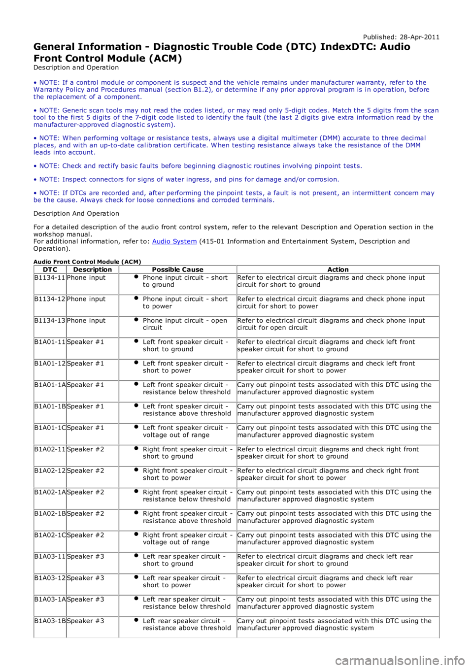
General Information - Diagnostic Trouble Code (DTC) IndexDTC: Audio
Front Control Module (ACM)
Des cript ion and Operat ion
• NOTE: If a cont rol module or component i s s uspect and the vehicl e remai ns under manufacturer warrant y, refer t o t heW arranty Pol icy and Procedures manual (s ect ion B1.2), or determine i f any pri or approval program is i n operat ion, beforet he replacement of a component.
• NOTE: Generic scan t ool s may not read the codes li st ed, or may read only 5-digi t codes . Match t he 5 digi ts from t he s cant ool t o t he fi rs t 5 di gi ts of the 7-digit code li s ted t o i dent ify the fault (the last 2 digi ts gi ve ext ra informati on read by themanufacturer-approved di agnos ti c s ys t em).
• NOTE: W hen performing volt age or res is t ance t est s , always use a digi tal mult imeter (DMM) accurat e t o t hree deci malplaces, and wi th an up-t o-date cal ibrat ion cert ificate. W hen tes ti ng res is t ance al ways take t he res is t ance of t he DMMleads i nt o account .
• NOTE: Check and recti fy bas ic faul ts before beginni ng diagnos t ic rout ines i nvol vi ng pinpoint t es t s.
• NOTE: Ins pect connect ors for s igns of water ingres s , and pins for damage and/or corros ion.
• NOTE: If DTCs are recorded and, aft er performi ng the pi npoi nt tes ts , a fault is not present , an int ermi tt ent concern maybe t he caus e. Always check for loose connect ions and corroded terminals .
Des cript ion And Operat ion
For a detail ed descripti on of the audio front control sys t em, refer t o t he rel evant Des cript ion and Operat ion s ecti on in theworks hop manual .For addit ional informat ion, refer t o: Audi o Sys tem (415-01 Informati on and Entertainment Sys tem, Des cript ion andOperat ion).
Audio Front C ontrol Module (AC M)
DT CDescriptionPossible CauseAction
B1134-11Phone inputPhone input ci rcuit - s hortt o groundRefer to electrical ci rcuit diagrams and check phone inputci rcuit for short to ground
B1134-12Phone inputPhone input ci rcuit - s hortt o powerRefer to electrical ci rcuit diagrams and check phone inputci rcuit for short to power
B1134-13Phone inputPhone input ci rcuit - opencircui tRefer to electrical ci rcuit diagrams and check phone inputci rcuit for open ci rcuit
B1A01-11Speaker #1Left front s peaker circuit -s hort t o groundRefer to electrical ci rcuit diagrams and check left fronts peaker ci rcuit for short to ground
B1A01-12Speaker #1Left front s peaker circuit -s hort t o powerRefer to electrical ci rcuit diagrams and check left fronts peaker ci rcuit for short to power
B1A01-1ASpeaker #1Left front s peaker circuit -res i st ance bel ow t hres hol dCarry out pi npoi nt tes ts as s oci ated wit h thi s DTC us ing t hemanufacturer approved diagnost ic sys tem
B1A01-1BSpeaker #1Left front s peaker circuit -res i st ance above t hres hol dCarry out pi npoi nt tes ts as s oci ated wit h thi s DTC us ing t hemanufacturer approved diagnost ic sys tem
B1A01-1CSpeaker #1Left front s peaker circuit -volt age out of rangeCarry out pi npoi nt tes ts as s oci ated wit h thi s DTC us ing t hemanufacturer approved diagnost ic sys tem
B1A02-11Speaker #2Right front s peaker ci rcuit -s hort t o groundRefer to electrical ci rcuit diagrams and check right fronts peaker ci rcuit for short to ground
B1A02-12Speaker #2Right front s peaker ci rcuit -s hort t o powerRefer to electrical ci rcuit diagrams and check right fronts peaker ci rcuit for short to power
B1A02-1ASpeaker #2Right front s peaker ci rcuit -res i st ance bel ow t hres hol dCarry out pi npoi nt tes ts as s oci ated wit h thi s DTC us ing t hemanufacturer approved diagnost ic sys tem
B1A02-1BSpeaker #2Right front s peaker ci rcuit -res i st ance above t hres hol dCarry out pi npoi nt tes ts as s oci ated wit h thi s DTC us ing t hemanufacturer approved diagnost ic sys tem
B1A02-1CSpeaker #2Right front s peaker ci rcuit -volt age out of rangeCarry out pi npoi nt tes ts as s oci ated wit h thi s DTC us ing t hemanufacturer approved diagnost ic sys tem
B1A03-11Speaker #3Left rear s peaker circui t -s hort t o groundRefer to electrical ci rcuit diagrams and check left rears peaker ci rcuit for short to ground
B1A03-12Speaker #3Left rear s peaker circui t -s hort t o powerRefer to electrical ci rcuit diagrams and check left rears peaker ci rcuit for short to power
B1A03-1ASpeaker #3Left rear s peaker circui t -res i st ance bel ow t hres hol dCarry out pi npoi nt tes ts as s oci ated wit h thi s DTC us ing t hemanufacturer approved diagnost ic sys tem
B1A03-1BSpeaker #3Left rear s peaker circui t -res i st ance above t hres hol dCarry out pi npoi nt tes ts as s oci ated wit h thi s DTC us ing t hemanufacturer approved diagnost ic sys tem
Page 111 of 3229
Publ is hed: 28-Apr-2011
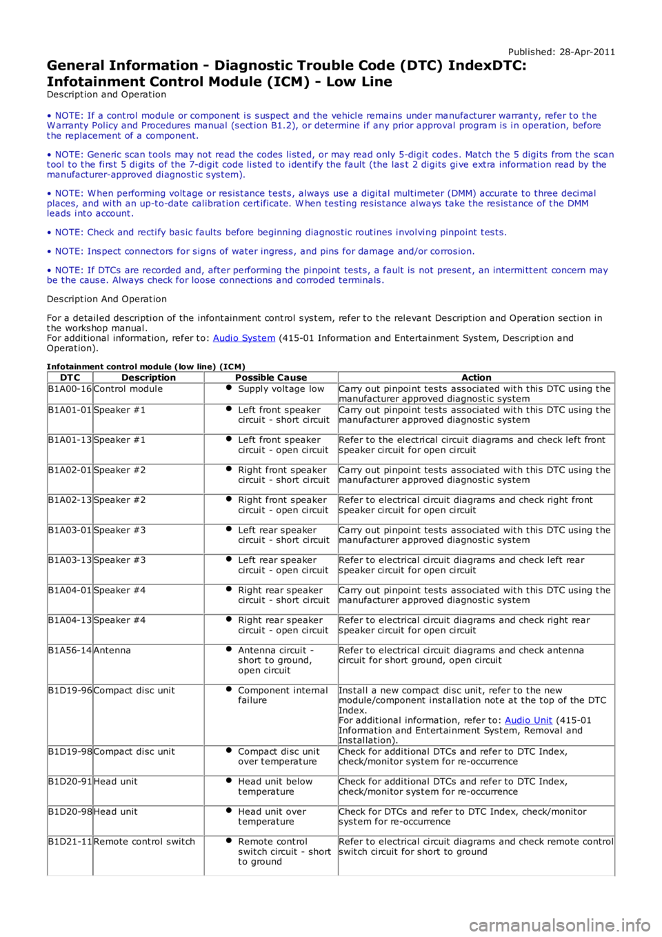
General Information - Diagnostic Trouble Code (DTC) IndexDTC:
Infotainment Control Module (ICM) - Low Line
Des cript ion and Operat ion
• NOTE: If a cont rol module or component i s s uspect and the vehicl e remai ns under manufacturer warrant y, refer t o t heW arranty Pol icy and Procedures manual (s ect ion B1.2), or determine i f any pri or approval program is i n operat ion, beforet he replacement of a component.
• NOTE: Generic scan t ool s may not read the codes li st ed, or may read only 5-digi t codes . Match t he 5 digi ts from t he s cant ool t o t he fi rs t 5 di gi ts of the 7-digit code li s ted t o i dent ify the fault (the last 2 digi ts gi ve ext ra informati on read by themanufacturer-approved di agnos ti c s ys t em).
• NOTE: W hen performing volt age or res is t ance t est s , always use a digi tal mult imeter (DMM) accurat e t o t hree deci malplaces, and wi th an up-t o-date cal ibrat ion cert ificate. W hen tes ti ng res is t ance al ways take t he res is t ance of t he DMMleads i nt o account .
• NOTE: Check and recti fy bas ic faul ts before beginni ng diagnos t ic rout ines i nvol vi ng pinpoint t es t s.
• NOTE: Ins pect connect ors for s igns of water ingres s , and pins for damage and/or corros ion.
• NOTE: If DTCs are recorded and, aft er performi ng the pi npoi nt tes ts , a fault is not present , an int ermi tt ent concern maybe t he caus e. Always check for loose connect ions and corroded terminals .
Des cript ion And Operat ion
For a detail ed descripti on of the infont ai nment cont rol s ys t em, refer t o t he rel evant Des cript ion and Operat ion secti on int he works hop manual .For addit ional informat ion, refer t o: Audi o Sys tem (415-01 Informati on and Entertainment Sys tem, Des cript ion andOperat ion).
Infotainment control module (low line) (IC M)
DT CDescriptionPossible CauseAction
B1A00-16Control modul eSuppl y volt age lowCarry out pi npoi nt tes ts ass ociated wit h t hi s DTC us ing t hemanufacturer approved diagnost ic sys tem
B1A01-01Speaker #1Left front s peakercircui t - short ci rcuitCarry out pi npoi nt tes ts ass ociated wit h t hi s DTC us ing t hemanufacturer approved diagnost ic sys tem
B1A01-13Speaker #1Left front s peakercircui t - open ci rcuitRefer t o the el ect ri cal circui t diagrams and check left fronts peaker ci rcuit for open ci rcuit
B1A02-01Speaker #2Right front s peakercircui t - short ci rcuitCarry out pi npoi nt tes ts ass ociated wit h t hi s DTC us ing t hemanufacturer approved diagnost ic sys tem
B1A02-13Speaker #2Right front s peakercircui t - open ci rcuitRefer t o electrical ci rcuit diagrams and check right fronts peaker ci rcuit for open ci rcuit
B1A03-01Speaker #3Left rear s peakercircui t - short ci rcuitCarry out pi npoi nt tes ts ass ociated wit h t hi s DTC us ing t hemanufacturer approved diagnost ic sys tem
B1A03-13Speaker #3Left rear s peakercircui t - open ci rcuitRefer t o electrical ci rcuit diagrams and check l eft rears peaker ci rcuit for open ci rcuit
B1A04-01Speaker #4Right rear s peakercircui t - short ci rcuitCarry out pi npoi nt tes ts ass ociated wit h t hi s DTC us ing t hemanufacturer approved diagnost ic sys tem
B1A04-13Speaker #4Right rear s peakercircui t - open ci rcuitRefer t o electrical ci rcuit diagrams and check right rears peaker ci rcuit for open ci rcuit
B1A56-14AntennaAntenna circui t -s hort t o ground,open circuit
Refer t o electrical ci rcuit diagrams and check antennacircuit for s hort ground, open circui t
B1D19-96Compact di sc uni tComponent i nternalfai lureIns t al l a new compact di s c uni t, refer t o t he newmodule/component i nst all ati on not e at t he t op of the DTCIndex.For addit ional informat ion, refer t o: Audi o Unit (415-01Informat ion and Ent ert ai nment Sys t em, Removal andIns t al lat ion).
B1D19-98Compact di sc uni tCompact di sc uni tover t emperat ureCheck for addi ti onal DTCs and refer to DTC Index,check/moni tor s ys t em for re-occurrence
B1D20-91Head unitHead unit belowt emperatureCheck for addi ti onal DTCs and refer to DTC Index,check/moni tor s ys t em for re-occurrence
B1D20-98Head unitHead unit overt emperatureCheck for DTCs and refer t o DTC Index, check/monit ors ys t em for re-occurrence
B1D21-11Remote cont rol s wit chRemote cont rols wit ch circuit - shortt o ground
Refer t o electrical ci rcuit diagrams and check remote controls wit ch ci rcuit for short to ground
Page 153 of 3229

Publ is hed: 26-Oct -2011
General Information - Diagnostic Trouble Code (DTC) IndexDTC: High
Definition Radio Module (HDR)
Des cript ion and Operat ion
• NOTE: If a cont rol module or component i s s uspect and the vehicl e remai ns under manufacturer warrant y, refer t o t heW arranty Pol icy and Procedures manual (s ect ion B1.2), or determine i f any pri or approval program is i n operat ion, beforet he replacement of a component.
• NOTE: Generic scan t ool s may not read the codes li st ed, or may read only 5-digi t codes . Match t he 5 digi ts from t he s cant ool t o t he fi rs t 5 di gi ts of the 7-digit code li s ted t o i dent ify the fault (the last 2 digi ts gi ve ext ra informati on read by themanufacturer-approved di agnos ti c s ys t em).
• NOTE: W hen performing volt age or res is t ance t est s , always use a digi tal mult imeter (DMM) accurat e t o t hree deci malplaces, and wi th an up-t o-date cal ibrat ion cert ificate. W hen tes ti ng res is t ance al ways take t he res is t ance of t he DMMleads i nt o account .
• NOTE: Check and recti fy bas ic faul ts before beginni ng diagnos t ic rout ines i nvol vi ng pinpoint t es t s.
• NOTE: Ins pect connect ors for s igns of water ingres s , and pins for damage and/or corros ion.
• NOTE: If DTCs are recorded and, aft er performi ng the pi npoi nt tes ts , a fault is not present , an int ermi tt ent concern maybe t he caus e. Always check for loose connect ions and corroded terminals .
Des cript ion And Operat ion
For a detail ed descripti on of the cell ular phone sys tem, refer t o t he rel evant Des cript ion and Operat ion s ecti on in theworks hop manual . For addit ional informat ion, refer t o: Audi o Syst em (415-01 Informati on and Entertainment Sys tem,Des cript ion and Operat ion).
Digital Audio Control Module C (DAC MC )DT CDescriptionPossible CauseAction
B1A56-02Antenna -general si gnalfai lure
Antenna general si gnal failureRefer t o t he electrical gui des and check the IBOC radiomodule ci rcuit and t he antenna for s hort t o power, opencircui t, hi gh res is t ance. Clear the di agnos ti c t roublecode and ret est . If the di agnos ti c troubl e code pers is ts ,check and i nst all a new IBOC radio modul e, as required.Refer t o t he warranty poli cy and procedures manual , ordetermine if any pri or approval programme is inoperat ion, prior t o t he ins t al lat ion of a new modul eB1A56-11Antenna - circui ts hort t o groundIBOC radio module or antennacircuit s hort t o groundRefer t o t he electrical gui des and check the IBOC radiomodule ci rcuit and t he antenna for s hort ci rcuit t oground
B1A56-12Antenna - circui ts hort t o batt eryIBOC radio module or antennacircuit s hort t o powerRefer t o t he electrical gui des and check the IBOC radiomodule ci rcuit and t he antenna for s hort ci rcuit t opower
B1A56-13Antenna - circui topenIBOC radio module or antennacircuit open circui tRefer t o t he electrical gui des and check the IBOC radiomodule ci rcuit and t he antenna for open circui t
U200D-14Control ModuleOut put Power A -circui t short toground or open
IBOC radio module powers uppl y ci rcuit s hort t o groundor open ci rcuit
Refer t o t he electrical gui des and check the IBOC radiomodule divers it y power ci rcuit for short to ground, opencircui t
U3000-04Control Module -s yst em i nternalfai lures
IBOC radio module i nternalfai lureRenew t he IBO C radi o module
U3000-4AControl Module -incorrectcomponentins t al led
IBOC radio module i nternalincorrect component i ns t alled -The module has been i ns t alledto a vehicle not configured toaccept it
Us ing the manufact urer approved di agnos ti c s yst ems elect the vehicle configurat ion mai n menu, s el ectconfigure exis ti ng modules menu and program t hemodule
U3000-55Control Module -not configuredIBOC radio module notconfigured correct lyUs ing the manufact urer approved di agnos ti c s yst ems elect the vehicle configurat ion mai n menu, s el ectconfigure exis ti ng modules menu and program t hemodule
U3000-87Control Module -mi ss i ng mes sageMis s ing mess ageUs ing the manufact urer approved di agnos ti c s yst ems elect the vehicle configurat ion mai n menu, s el ectconfigure exis ti ng modules menu and program t hemoduleU3000-98Control Module -component ors yst em overt emperature
IBOC radio module componentor sys t em over temperat ureCons ider movi ng t he IBOC radio modul e t o prevent uni toverheati ng. Cool the vehicle int erior down by ens uri ngi t is i n t he s hade and have t he A/C on cool . W hen cool,clear t he diagnos t ic t rouble code and retes tU3003-62Batt ery Vol tage -s ignal comparefai lure
Mis mat ch in bat tery volt age of2 volt s or more for l onger than1 mi nute, between t hemeas ured batt ery volt age atthe IBOC radio modul e and t hebatt ery volt age s ignal s entfrom t he rear junct ion box
Refer t o t he electrical gui des and check that powers uppl y volt age at IBOC radio modul e and rear junct ionbox i s not di fferent by more than 2 vol ts . Recti fy asrequi red
Authori ng Templat e
Page 1805 of 3229
Publi s hed: 11-May-2011
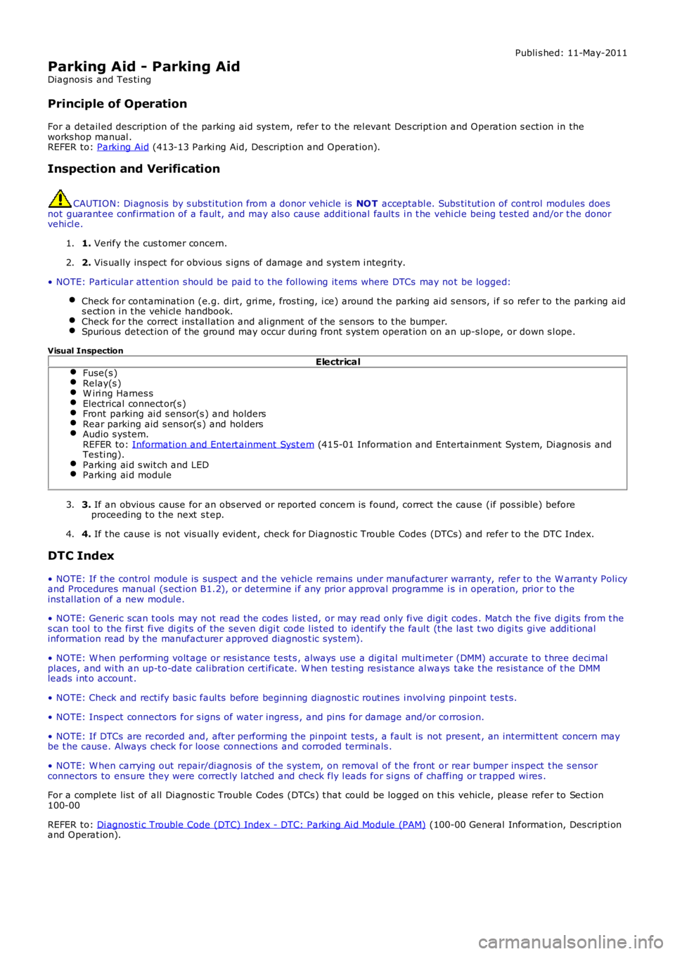
Parking Aid - Parking Aid
Diagnosi s and Tes ti ng
Principle of Operation
For a detail ed descripti on of the parki ng aid sys tem, refer t o t he rel evant Des cription and Operat ion s ecti on in theworks hop manual .REFER to: Parki ng Aid (413-13 Parki ng Aid, Descripti on and Operat ion).
Inspection and Verification
CAUTION: Di agnos is by s ubs ti tut ion from a donor vehicle is NO T acceptabl e. Subs ti tut ion of cont rol modules doesnot guarant ee confirmat ion of a faul t, and may als o caus e addit ional fault s i n t he vehi cl e being t est ed and/or t he donorvehi cl e.
1. Verify t he cus t omer concern.1.
2. Vis ually ins pect for obvious s igns of damage and s ys t em i ntegri ty.2.
• NOTE: Part icular att enti on s hould be paid t o t he fol lowi ng it ems where DTCs may not be logged:
Check for cont aminati on (e.g. dirt, gri me, fros ti ng, i ce) around t he parking ai d s ensors, i f s o refer to the parki ng aids ect ion i n t he vehi cl e handbook.Check for the correct ins tall ati on and ali gnment of t he s ens ors to t he bumper.Spurious det ect ion of t he ground may occur duri ng front s ys t em operat ion on an up-s lope, or down s l ope.
Visual Inspection
ElectricalFuse(s )Relay(s )W iri ng Harnes sElectrical connect or(s )Front parking ai d s ensor(s ) and holdersRear parking aid s ens or(s ) and hol dersAudio s ys tem.REFER to: Informati on and Entert ainment Syst em (415-01 Informati on and Entertainment Sys tem, Di agnos is andTes ti ng).Parking ai d s wit ch and LEDParking ai d module
3. If an obvious cause for an obs erved or report ed concern is found, correct t he caus e (if pos s ible) beforeproceeding t o t he next s t ep.3.
4. If t he caus e is not vis ually evi dent , check for Di agnos ti c Trouble Codes (DTCs) and refer t o t he DTC Index.4.
DTC Index
• NOTE: If the control modul e is sus pect and t he vehicle remains under manufact urer warranty, refer to the W arrant y Poli cyand Procedures manual (s ect ion B1.2), or determine i f any prior approval programme is i n operat ion, prior t o t heins t al lat ion of a new modul e.
• NOTE: Generic scan t ool s may not read the codes li st ed, or may read only fi ve digit codes . Mat ch the five di git s from t hes can tool to the firs t fi ve di git s of the seven digi t code l is ted to ident ify t he faul t (t he las t t wo digi ts gi ve addi ti onalinformat ion read by the manufact urer approved diagnos t ic s ys tem).
• NOTE: W hen performing volt age or res is t ance t est s , always use a digi tal mult imeter (DMM) accurat e t o t hree deci malplaces, and wi th an up-t o-date cal ibrat ion cert ificate. W hen tes ti ng res is t ance al ways take t he res is t ance of t he DMMleads i nt o account .
• NOTE: Check and recti fy bas ic faul ts before beginni ng diagnos t ic rout ines i nvol vi ng pinpoint t es t s.
• NOTE: Ins pect connect ors for s igns of water ingres s , and pins for damage and/or corros ion.
• NOTE: If DTCs are recorded and, aft er performi ng the pi npoi nt tes ts , a fault is not present , an int ermi tt ent concern maybe t he caus e. Always check for loose connect ions and corroded terminals .
• NOTE: W hen carrying out repair/di agnos is of t he s yst em, on removal of t he front or rear bumper ins pect t he s ensorconnectors to ens ure they were correct ly l atched and check fly l eads for si gns of chaffing or t rapped wi res .
For a compl ete lis t of all Di agnos ti c Trouble Codes (DTCs) t hat could be logged on this vehicle, pleas e refer to Sect ion100-00
REFER to: Di agnos ti c Trouble Code (DTC) Index - DTC: Parking Ai d Module (PAM) (100-00 General Informat ion, Des cri pti onand Operat ion).
Page 1867 of 3229
Publi s hed: 11-May-2011
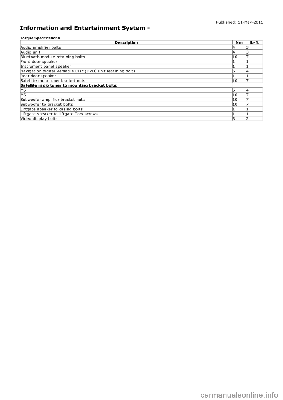
Information and Entertainment System -
Torque SpecificationsDescriptionNmlb-ft
Audio ampl ifier bolt s43
Audio uni t43Bluet oot h module ret aining bolt s107
Front door speaker11
Inst rument panel s peaker11Navigati on digit al Vers ati le Di s c (DVD) unit retai ni ng bolt s64
Rear door s peaker11
Satel lit e radio t uner bracket nuts107Satellite radio tuner to mounting bracket bolts:
M564
M6107Subwoofer amplifier bracket nut s107
Subwoofer to bracket bolt s107
Liftgat e s peaker to cas ing bol ts11Liftgat e s peaker to li ft gat e Torx screws11
Video di spl ay bol ts32
Page 1868 of 3229
Publi s hed: 11-May-2011
Information and Entertainment System - Audio System
Des cript ion and Operat ion
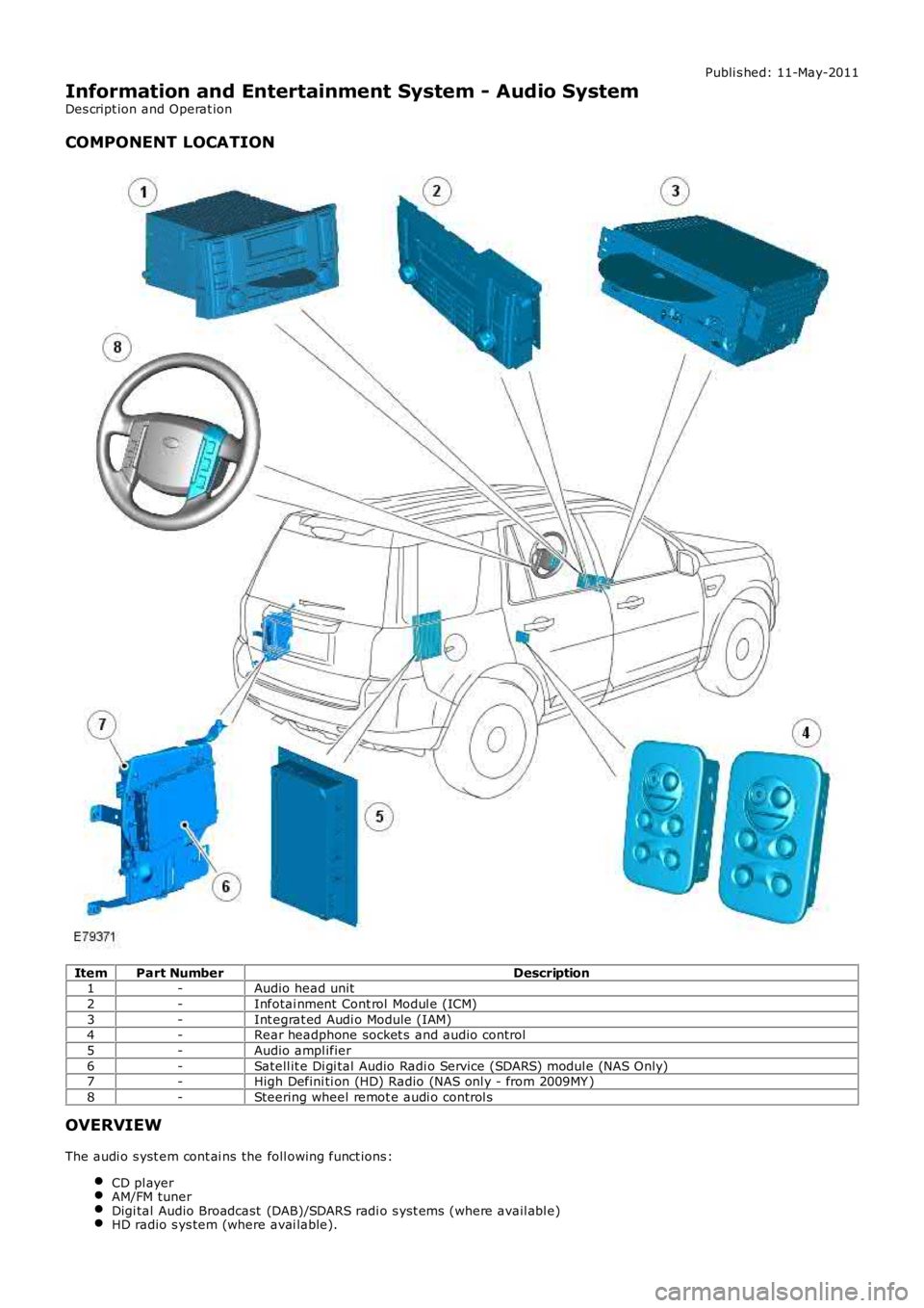
COMPONENT LOCATION
ItemPart NumberDescription1-Audio head unit
2-Infotai nment Cont rol Modul e (ICM)
3-Int egrat ed Audi o Module (IAM)4-Rear headphone socket s and audio control
5-Audio ampl ifier
6-Satell it e Di gi tal Audio Radi o Service (SDARS) modul e (NAS Only)7-High Defini ti on (HD) Radio (NAS onl y - from 2009MY )
8-Steering wheel remot e audi o control s
OVERVIEW
The audi o s yst em cont ai ns the foll owing funct ions :
CD pl ayerAM/FM tunerDigi tal Audio Broadcast (DAB)/SDARS radi o s yst ems (where avail abl e)HD radio s ys tem (where avai lable).
Page 1877 of 3229
Publi s hed: 11-May-2011
Information and Entertainment System - Speakers
Des cript ion and Operat ion
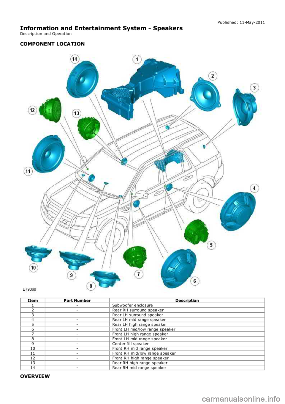
COMPONENT LOCATION
ItemPart NumberDescription1-Subwoofer encl osure
2-Rear RH s urround s peaker
3-Rear LH s urround speaker4-Rear LH mi d range speaker
5-Rear LH high range s peaker
6-Front LH mid/low range s peaker7-Front LH hi gh range s peaker
8-Front LH mid range s peaker
9-Cent er fil l speaker10-Front RH mid range s peaker
11-Front RH mid/low range s peaker
12-Front RH high range speaker13-Rear RH hi gh range s peaker
14-Rear RH mid range speaker
OVERVIEW
Page 1900 of 3229
Publi s hed: 11-May-2011
Information and Entertainment System - Rear Door Speaker
Removal and Inst all ati on
Removal
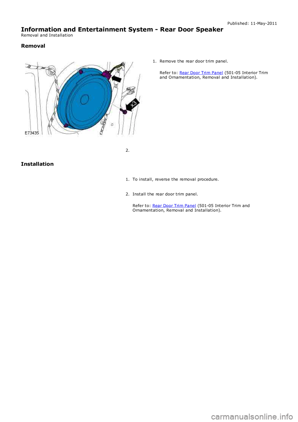
Remove t he rear door t rim panel.
Refer t o: Rear Door Tri m Panel (501-05 Int erior Tri mand Ornament ati on, Removal and Ins tal lat ion).
1.
2.
Installation
To i nst all , revers e t he removal procedure.1.
Inst all t he rear door t rim panel.
Refer t o: Rear Door Tri m Panel (501-05 Int erior Tri m andOrnament ati on, Removal and Ins tal lat ion).
2.