2006 LAND ROVER FRELANDER 2 roof rack
[x] Cancel search: roof rackPage 29 of 3229
Rear seat belt s
Side Curtain Airbag Modul es
CAUTION: If the head ai rbag modules are depl oyed, t he fol lowing component s mus t be replaced on the si de of thevehi cl e on whi ch the deployment occurred:
Side curt ain ai rbag modulesHeadl iner and all pil lar t ri msLink l ead bet ween airbag gas generat or and RCM harnes sAirbag ret aining cli psFront s eat bel t buckle pre-t ens i onersAny s ide i mpact s ens ors t hat have been phys i cal ly damaged or if a fault i s being regi st eredRCM
Additionally, the following items must be inspected for damage and replaced as necessary:
Component mount ing bracketsFront s eat bel ts , ret ractors and webbing, tongue lat chi ng functi on, 'D' l oop and body anchorage point sRear seat belt buckl es, webbing, buckle covers , t ongue l atching funct ion, and body anchorage point sAdjacent t rim componentsSeat bel t hei ght adjust ers
Rear impacts
CAUTION: If the s eat belt pre-tens ioners are deployed during a rear i mpact , the following component s mus t berepl aced:
Seat bel t pre-t ensi onersFront and rear s eat bel t ret ractors used during t he i mpactRCM
Additionally, the following items must be inspected for damage and replaced as necessary:
Seat bel t hei ght adjust ersFront s eat bel ts , ret ractors and webbing, tongue lat chi ng functi on, 'D' l oop and body anchorage point sRear seat belt buckl es, webbing, buckle covers , t ongue l atching funct ion, and body anchorage point s
Air Conditioning System Precautions
The air condi ti oni ng s yst em contai ns fl ui ds and components which coul d be pot ent ially hazardous to the s ervi ce engineeror the environment if not serviced and handl ed correctl y. The foll owing guideli nes are i ntended to alert t he s erviceengi neer t o pot ent ial s ources of danger and emphas is e t he i mport ance of ens uring t he i nt egri ty of t he Air Condit ioningoperati ng condi ti ons and component s i ns t alled to the vehicle.
W here neces s ary, addi ti onal s pecific precaut ions are det ail ed in t he relevant s ecti ons of t his Manual and als o in the Heal thand Safet y Sect ion. Thes e precauti ons mus t be referred to prior t o commenci ng repair operat ions .
The refri gerant us ed i n t he air condi ti oni ng s ys t em i s HFC-134a (Hydrofl uorocarbon) R134a.
• W ARNINGS:
Servi ci ng mus t onl y be carried out by pers onnel famil iar wit h bot h t he vehi cl e s ys tem and t he charging and t es ti ngequi pment. Al l operat ions mus t be carried out i n a wel l venti lat ed area away from open fl ame and heat sources .
R134a is a hazardous l iquid and when handl ed incorrect ly can caus e s erious injury. Sui table prot ect ive clot hi ng,cons is t ing of face protecti on, heat proof gloves, rubber boots and rubber apron or waterproof overal ls , mus t be worn whencarryi ng out operat ions on t he air condit ioning s ys tem.
Remedial act ions
W ARNING: Due to it s low evaporat ing t emperat ure, R134a must be handled wit h care. R134a spl as hed on any part oft he body will cause immedi ate freezing of t hat area. Als o, refrigerant cylinders and replenis hment t roll eys whendis charging wi ll freeze s ki n t o t hem if contact is made.
If an accident involving R134a s houl d occur, conduct t he followi ng remedi al acti ons :
If liquid R134a ent ers t he eye, do not rub i t. Gentl y run large quant it ies of eye wash over affected eye t o rai s e t het emperature. If an eye was h is not avail abl e, cool, clean wat er may be us ed t o fl ush the eye. Aft er ri nsi ng, covert he eye wit h a clean pad and s eek i mmediat e medical at t ent ion.If liquid R134a is s plas hed ont o t he s kin, run large quanti ti es of water over t he affected area to rais e thet emperature. Implement t he s ame acti on if t he s kin comes i n cont act wi th dis chargi ng cyl inders . W rap t hecont aminat ed body parts in bl ankets (or s imi lar mat eri al s ) and seek i mmediat e medical att ent ion.If the debil it at ing effect s of inhalati on of R134a vapour are s us pect ed, s eek fresh air. If t he affect ed pers on isuncons ci ous , move t hem away from t he cont aminated area t o fres h air and apply arti fici al respi rat ion and/or oxygenand s eek immedi at e medi cal at tenti on.
Service precauti ons
Obs erve t he fol lowing precaut ions when handl ing component s us ed in the ai r condit ioning s ys tem:
Page 31 of 3229
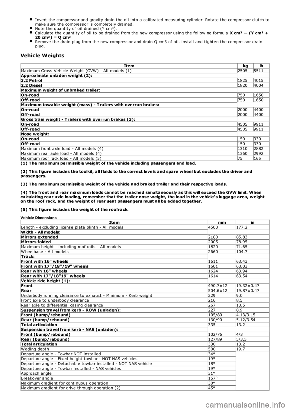
Invert the compres s or and gravi ty drain the oi l into a calibrated meas uri ng cyl inder. Rotat e t he compres sor clut ch tomake s ure the compres s or is complet el y drai ned.Note the quanti ty of oi l drained (Y cm³).Calculate the quanti ty of oi l to be drained from t he new compres sor us ing t he fol lowi ng formula:X cm³ — (Y cm³ +20 cm³) = Q cm³Remove the drain pl ug from the new compres s or and drain Q cm3 of oi l. ins t al l and tight en t he compres sor drai nplug.
Vehicle Weights
Itemkglb
Maximum Gros s Vehicle W eight (GVW ) - Al l model s (1)25055511Approximate unladen w eight (2):
3.2 Petrol18254015
2.2 Diesel18204004Maximum weight of unbraked trailer:
On-road7501650
Off-road7501650Maximum towable weight (mass) - T railers with overrun brakes:
On-road20004400
Off-road20004400Gross train weight - T railers with overrun brakes (3):
On-road45059911
Off-road45059911Nose w eight:
On-road150330
Off-road150330Maximum front axl e l oad - All models (4)13102882
Maximum rear axle load - All models (4)13602992
Maximum roof rack l oad - All models (5)75165(1) T he maximum permissible weight of the vehicle including passengers and load.
(2) T his figure includes the toolkit, all fluids to the correct levels and spare w heel but excludes the driver andpassengers.
(3) T he maximum permissible weight of the vehicle and braked trailer and their respective loads.
(4) T he front and rear maximum loads cannot be reached simultaneously as this will exceed the GVW limit. Whencalculating rear axle loading, remember that the trailer nose w eight, the load in the vehicle' s luggage area, w eighton the roof rack, and the weight of rear seat passengers must all be added together.
(5) T his figure includes the weight of the roofrack.
Vehicle Dimensions
ItemmminLengt h - excluding l icens e pl ate pl int h - All models4500177.2
Width - All models:
Mirrors extended218085.83Mirrors folded200578.95
Maximum height - including roof rail s - Al l model s182071.65
W heelbas e - Al l model s2660104.7T rack:
Front w ith 16" wheels161163.43
Front w ith 17"/18"/19" wheels160163.03Rear with 16" wheels162463.94
Rear with 17"/18"19" wheels161463.54
Vehicle ride height (1):Front490.7±1219.32±0.47
Rear504.6±1219.87±0.47
Underbody running cl earance t o exhaus t - Mi nimum - Kerb wei ght2299.0Front axle t o underbody clearance2168.5
Rear axl e t o different ial cas i ng cl earance26710.5
Suspension travel from kerb - ROW (unladen):2278.9Front (bump/rebound)105/804.13/3.15
Rear (bump/rebound)130/905.12/3.54
T otal articulation33513.2Suspension travel from kerb - NAS (unladen):
Front (bump/rebound)102/764/3
Rear (bump/rebound)127/895/3.5T otal articulation33013.2
W adi ng dept h50019.7
Depart ure angle - Towbar NOT ins tall ed34°Depart ure angle - Fi xed hei ght towbar - NOT NAS vehicles19°
Depart ure angle - Detachabl e towbar ins t al led - NOT NAS vehicle18°
Depart ure angle - Towbar i ns t alled - NAS vehi cl es19°Approach angl e31°
Breakover angle157°
Maximum gradient for conti nuous operat ion30°Maximum gradient for drive t hrough operat ion (2)45°
Page 1372 of 3229
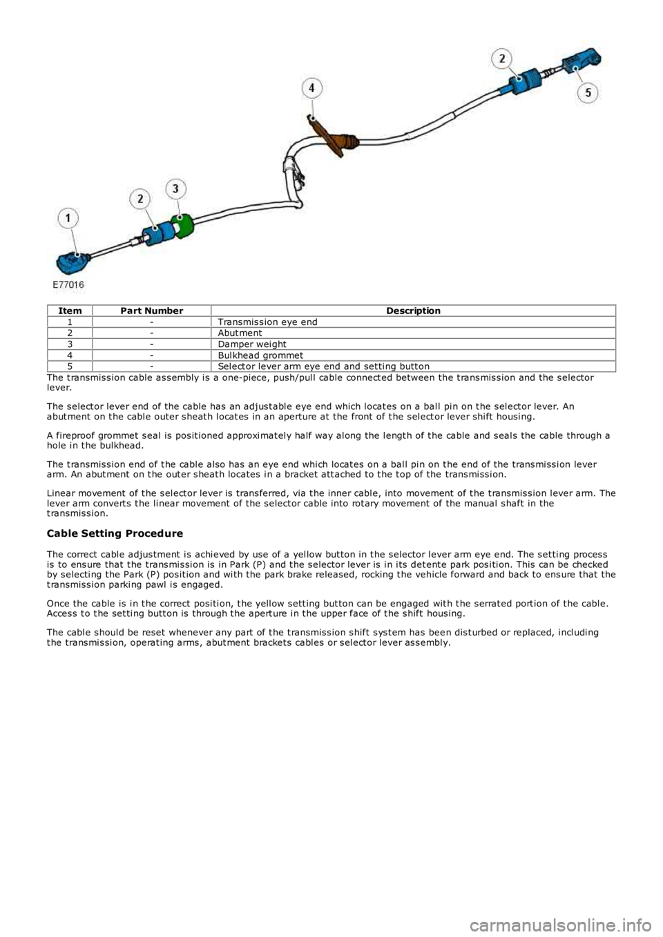
ItemPart NumberDescription
1-Transmis s ion eye end2-Abut ment
3-Damper wei ght
4-Bul khead grommet5-Sel ect or lever arm eye end and set ti ng butt on
The t ransmis s ion cable as s embly i s a one-pi ece, push/pul l cable connect ed between the t rans mis s ion and the s electorlever.
The s elect or lever end of the cable has an adjus t abl e eye end which l ocat es on a ball pi n on t he s el ect or lever. Anabut ment on t he cabl e outer s heat h l ocat es in an aperture at the front of t he s el ector lever shi ft housi ng.
A fireproof grommet s eal is pos it ioned approxi mat el y half way al ong the l engt h of t he cable and s eal s the cable through ahole i n t he bulkhead.
The t ransmis s ion end of t he cabl e als o has an eye end whi ch locat es on a bal l pi n on t he end of the trans mi ss i on leverarm. An abut ment on t he out er s heat h locates i n a bracket att ached to t he t op of the trans mi ss i on.
Linear movement of t he s el ect or lever is t rans ferred, via t he inner cabl e, into movement of t he t ransmis s ion l ever arm. Thelever arm convert s t he li near movement of the s elect or cable i nto rot ary movement of the manual s haft in thet ransmis s ion.
Cable Setting Proced ure
The correct cabl e adjus tment i s achi eved by use of a yel low but ton in t he s elector lever arm eye end. The s et ti ng proces sis to ens ure that t he trans mi s si on is in Park (P) and t he s elector lever is i n i ts det ent e park pos i ti on. This can be checkedby s electi ng the Park (P) pos it ion and wi th the park brake released, rocking t he vehicle forward and back to ens ure that thet ransmis s ion parki ng pawl i s engaged.
Once the cable is i n t he correct posi ti on, t he yell ow s ett ing but ton can be engaged wit h t he s errat ed port ion of t he cabl e.Acces s t o t he set ti ng butt on is through t he apert ure i n t he upper face of t he s hift hous ing.
The cabl e s houl d be reset whenever any part of t he t ransmis s ion s hift s ys t em has been dis t urbed or replaced, i ncl udi ngt he trans mi s si on, operat ing arms , abut ment bracket s cabl es or s el ect or lever as s embly.
Page 1589 of 3229
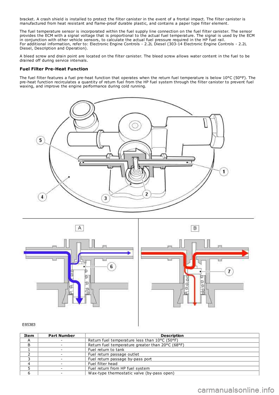
bracket . A cras h s hiel d is ins tal led t o prot ect t he filt er cani st er in the event of a front al impact. The fil ter cani s ter ismanufactured from heat res is t ant and flame-proof durable pl ast ic, and cont ains a paper t ype fil ter element .
The fuel t emperature s ens or is incorporated wit hin t he fuel s uppl y li ne connecti on on t he fuel fi lt er canis t er. The s ens orprovides t he ECM wi th a s ignal vol tage t hat is proporti onal t o the act ual fuel t emperat ure. The s ignal i s us ed by the ECMin conjuncti on wi th ot her vehicle s ens ors , t o cal cul ate the actual fuel pres s ure requi red i n t he HP fuel rail .For addit ional informat ion, refer t o: Electroni c Engi ne Controls - 2.2L Dies el (303-14 El ect ronic Engine Cont rols - 2.2LDies el, Des cript ion and Operat ion).
A bl eed screw and drai n point are locat ed on t he fi lt er canis t er. The bleed s crew allows wat er cont ent in t he fuel t o bedrai ned off during servi ce int ervals .
Fuel Filter Pre-Heat Function
The fuel filt er feat ures a fuel pre-heat functi on that operates when the return fuel t emperature is bel ow 10°C (50°F). Thepre-heat funct ion reci rculat es a quant it y of ret urn fuel from t he HP fuel s ys tem through the fil ter cani s ter t o prevent fuelwaxing, and improve the engine performance during cold runni ng.
ItemPart NumberDescriptionA-Ret urn fuel t emperat ure l es s t han 10°C (50°F)
B-Ret urn fuel t emperat ure great er than 20°C (68°F)
1-Fuel return t o t ank2-Fuel return pas sage out let
3-Fuel return pas sage by-pas s port
4-Fuel fil ter head5-Fuel return from HP fuel s yst em
6-W ax-type t hermos tat ic valve (by-pas s open)
Page 1873 of 3229
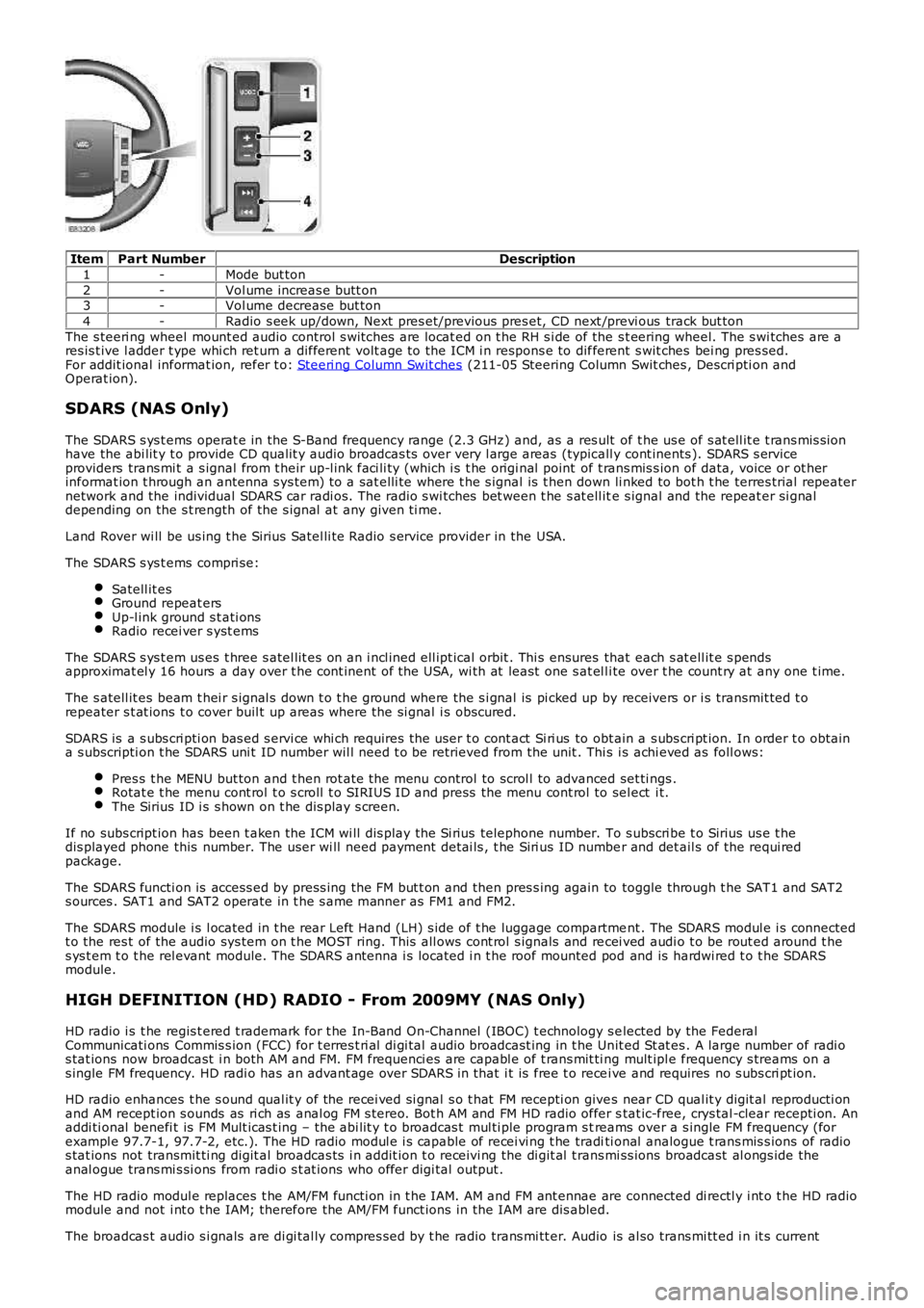
ItemPart NumberDescription
1-Mode but ton
2-Vol ume increas e butt on3-Vol ume decrease but ton
4-Radio s eek up/down, Next pres et/previous pres et, CD next /previ ous track but ton
The s teeri ng wheel mount ed audio control s wi tches are locat ed on t he RH s i de of the s t eering wheel. The s wi tches are ares is t ive l adder t ype whi ch ret urn a different volt age to the ICM i n respons e to different s wit ches bei ng pres sed.For addit ional informat ion, refer t o: Steeri ng Column Swit ches (211-05 Steering Column Swit ches , Descri pti on andOperat ion).
SDARS (NAS Only)
The SDARS s ys t ems operat e in the S-Band frequency range (2.3 GHz) and, as a res ult of t he us e of s at ell it e t rans mis s ionhave the abi lit y t o provide CD qualit y audio broadcas ts over very l arge areas (typicall y cont inents ). SDARS s erviceproviders trans mi t a s ignal from t heir up-l ink faci li ty (which i s t he origi nal point of t rans mis s ion of data, voice or ot herinformat ion t hrough an antenna s ys tem) t o a sat elli te where t he s ignal is t hen down li nked to bot h t he terres trial repeaternetwork and the individual SDARS car radi os. The radio s wi tches bet ween t he s at ell ite s ignal and the repeat er si gnaldepending on the s t rength of the s ignal at any given ti me.
Land Rover wi ll be us ing t he Sirius Satel li te Radio s ervice provider in the USA.
The SDARS s ys t ems compri se:
Satell it esGround repeat ersUp-l ink ground s t ati onsRadio recei ver s yst ems
The SDARS s ys t em us es t hree s atel lit es on an i ncl ined ell ipt ical orbit . Thi s ensures that each s at ell it e s pendsapproximat el y 16 hours a day over t he cont inent of the USA, wi th at least one s at el li te over t he count ry at any one t ime.
The s atell it es beam t hei r s ignal s down t o t he ground where the s i gnal is pi cked up by receivers or i s transmit ted t orepeater s t at ions t o cover buil t up areas where the si gnal i s obscured.
SDARS is a s ubs cri pti on bas ed s ervi ce whi ch requires the us er t o cont act Si ri us to obt ain a s ubs cri pt ion. In order t o obtaina s ubscripti on t he SDARS uni t ID number wil l need t o be retrieved from the unit . This i s achi eved as foll ows:
Pres s t he MENU but ton and t hen rot ate the menu control to scrol l to advanced set ti ngs .Rotat e t he menu cont rol t o s croll t o SIRIUS ID and press the menu cont rol to sel ect i t.The Sirius ID i s s hown on t he dis play s creen.
If no subs cript ion has been t aken the ICM wi ll dis play the Si rius telephone number. To s ubscri be t o Sirius us e t hedis played phone this number. The user wi ll need payment det ai ls , t he Siri us ID number and det ail s of the requi redpackage.
The SDARS functi on is access ed by press ing the FM but t on and then pres s ing again to toggle through t he SAT1 and SAT2s ources . SAT1 and SAT2 operate in t he s ame manner as FM1 and FM2.
The SDARS module i s l ocated in t he rear Left Hand (LH) s ide of t he luggage compartment . The SDARS modul e i s connectedt o the res t of the audio sys tem on t he MOST ring. This all ows cont rol s ignals and recei ved audi o t o be rout ed around t hes ys t em t o t he rel evant module. The SDARS antenna i s located i n t he roof mounted pod and is hardwi red t o t he SDARSmodule.
HIGH DEFINITION (HD) RADIO - From 2009MY (NAS Only)
HD radio i s t he regis t ered t rademark for t he In-Band On-Channel (IBOC) t echnology s elected by the FederalCommunicati ons Commis s ion (FCC) for t erres t ri al di gi tal audio broadcast ing in t he Unit ed St at es . A large number of radi os tat ions now broadcast i n both AM and FM. FM frequenci es are capabl e of t rans mit ti ng mult ipl e frequency s treams on as ingle FM frequency. HD radi o has an advant age over SDARS in that i t is free t o recei ve and requires no s ubs cri pt ion.
HD radio enhances t he s ound qual it y of the recei ved si gnal s o t hat FM recepti on gives near CD qual it y digit al reproducti onand AM recept ion s ounds as ri ch as anal og FM s tereo. Bot h AM and FM HD radio offer stat ic-free, crys tal -clear recepti on. Anaddi ti onal benefi t is FM Mult icas t ing – the abi lit y t o broadcas t mul ti ple program s treams over a s ingle FM frequency (forexampl e 97.7-1, 97.7-2, etc.). The HD radio modul e i s capable of recei vi ng t he traditi onal analogue t rans mis s ions of radios tat ions not transmit ti ng digit al broadcas ts i n addit ion t o receivi ng the di git al t rans mi ss ions broadcast al ongs ide theanal ogue trans mi s si ons from radi o s t at ions who offer digi tal output .
The HD radio modul e replaces t he AM/FM functi on in t he IAM. AM and FM ant ennae are connected di rectl y i nt o t he HD radiomodule and not i nt o t he IAM; therefore the AM/FM funct ions in the IAM are dis abled.
The broadcas t audio s i gnals are di gi tal ly compres s ed by t he radio trans mi tt er. Audio is al so trans mi tt ed i n it s current
Page 2368 of 3229
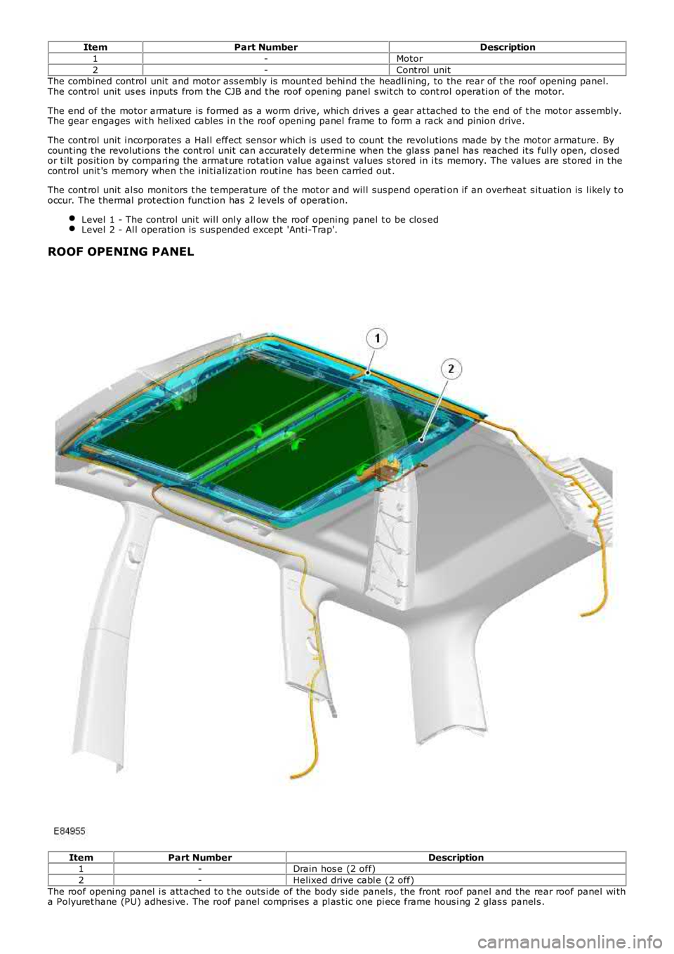
ItemPart NumberDescription
1-Motor
2-Cont rol unitThe combined cont rol unit and mot or ass embly is mount ed behi nd t he headli ning, to the rear of t he roof opening panel.The cont rol unit us es inputs from t he CJB and t he roof openi ng panel s wit ch to cont rol operati on of the motor.
The end of the motor armat ure is formed as a worm drive, whi ch dri ves a gear at tached to the end of t he mot or as s embly.The gear engages wit h heli xed cables i n t he roof openi ng panel frame to form a rack and pinion drive.
The cont rol unit i ncorporates a Hal l effect s ensor which i s us ed to count t he revolut ions made by t he mot or armature. Bycount ing t he revolut ions t he cont rol unit can accurat ely det ermi ne when t he glas s panel has reached it s ful ly open, cl osedor ti lt pos it ion by compari ng the armat ure rotat ion value agains t values s tored in its memory. The values are st ored in t hecont rol unit 's memory when t he i ni ti alizat ion rout ine has been carried out .
The cont rol unit al so monit ors t he temperature of the mot or and wil l sus pend operation if an overheat s it uat ion is l ikely t ooccur. The t hermal prot ect ion funct ion has 2 levels of operat ion.
Level 1 - The control uni t wil l onl y all ow t he roof openi ng panel t o be clos edLevel 2 - Al l operati on is s us pended except 'Ant i-Trap'.
ROOF OPENING PANEL
ItemPart NumberDescription1-Drain hos e (2 off)
2-Helixed drive cabl e (2 off)
The roof openi ng panel i s att ached t o t he outs i de of the body s ide panels , the front roof panel and the rear roof panel wi tha Polyuret hane (PU) adhesi ve. The roof panel compris es a pl as t ic one pi ece frame hous i ng 2 glas s panel s .
Page 2378 of 3229
1
1
1
2
3
4
1
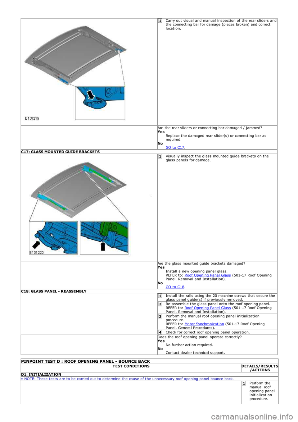
Carry out vis ual and manual ins pect ion of t he rear s liders andthe connecting bar for damage (pieces broken) and correctlocat ion.
Are t he rear sliders or connecting bar dama ged / jamme d?YesReplace t he damaged rear sli der(s ) or connect ing bar asrequired.NoGO to C17.C17: GLASS MOUNT ED GUIDE BRACKET SVis ually ins pect the glass mounted guide bra cket s on t heglass pane ls for da mage.
Are t he glas s mount ed guide bracket s damaged?YesIns tall a new opening pane l glass.REFER to: Roof Opening Panel Glass (501-17 Roof OpeningPanel, Removal and Inst allat ion).NoGO to C18.C18: GLASS PANEL - REASSEMBLYIns tall t he rails us ing the 20 ma chine s crews that secure theglass pane l guide(s) if previously removed.Re-as semble t he glass panel ont o the roof opening panel.REFER to: Roof Opening Panel Glass (501-17 Roof OpeningPanel, Removal and Inst allat ion).Perform t he manua l roof opening panel init ializat ionprocedure.REFER to: Motor Synchronizat ion (501-17 Roof Openi ngPanel, Genera l P rocedures).Che ck for correct roof opening panel operat ion.Doe s the roof opening panel operat e correctly?YesNo furt her act ion required.NoContact de aler t echnica l s upport .
PINPOINT TEST D : ROOF OPENING PANEL - BOUNCE BACKT EST CONDIT IONSDETAILS/RESULT S/ACT IONSD1: INIT IALIZAT ION• NOTE: These t est s are to be carried out t o det ermine t he caus e of t he unne cess ary roof opening panel bounce back.Perform themanual roofopening panelinit ializat ionproce dure.
Page 2384 of 3229
1
1
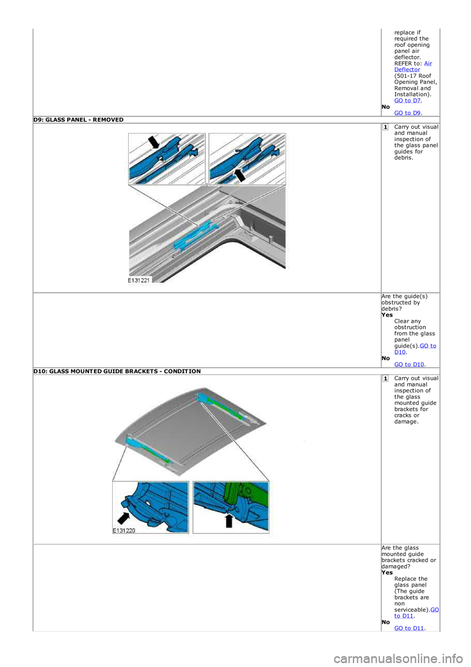
replace ifrequired t heroof openingpanel airdeflector.REFER t o: AirDeflect or(501-17 RoofOpening Panel,Remova l a ndInst allat ion).GO t o D7.NoGO t o D9.D9: GLASS PANEL - REMOVEDCarry out visualand manualinspe ct ion oft he glass pa nelguides fordebris.
Are t he guide(s)obs tructed bydebris ?YesClear anyobst ructionfrom the glasspanelguide(s).GO t oD10.NoGO t o D10.D10: GLASS MOUNT ED GUIDE BRACKETS - CONDIT IONCarry out visualand manualinspe ct ion oft he glassmount ed guidebracket s forcracks ordamage .
Are t he glassmounted guidebracket s cracked ordama ged?YesReplace theglass panel(The guidebracket s arenonservi ceable).GOt o D11.NoGO t o D11.