2006 LAND ROVER FRELANDER 2 roof rack
[x] Cancel search: roof rackPage 2386 of 3229
1
2
1
2
3
1
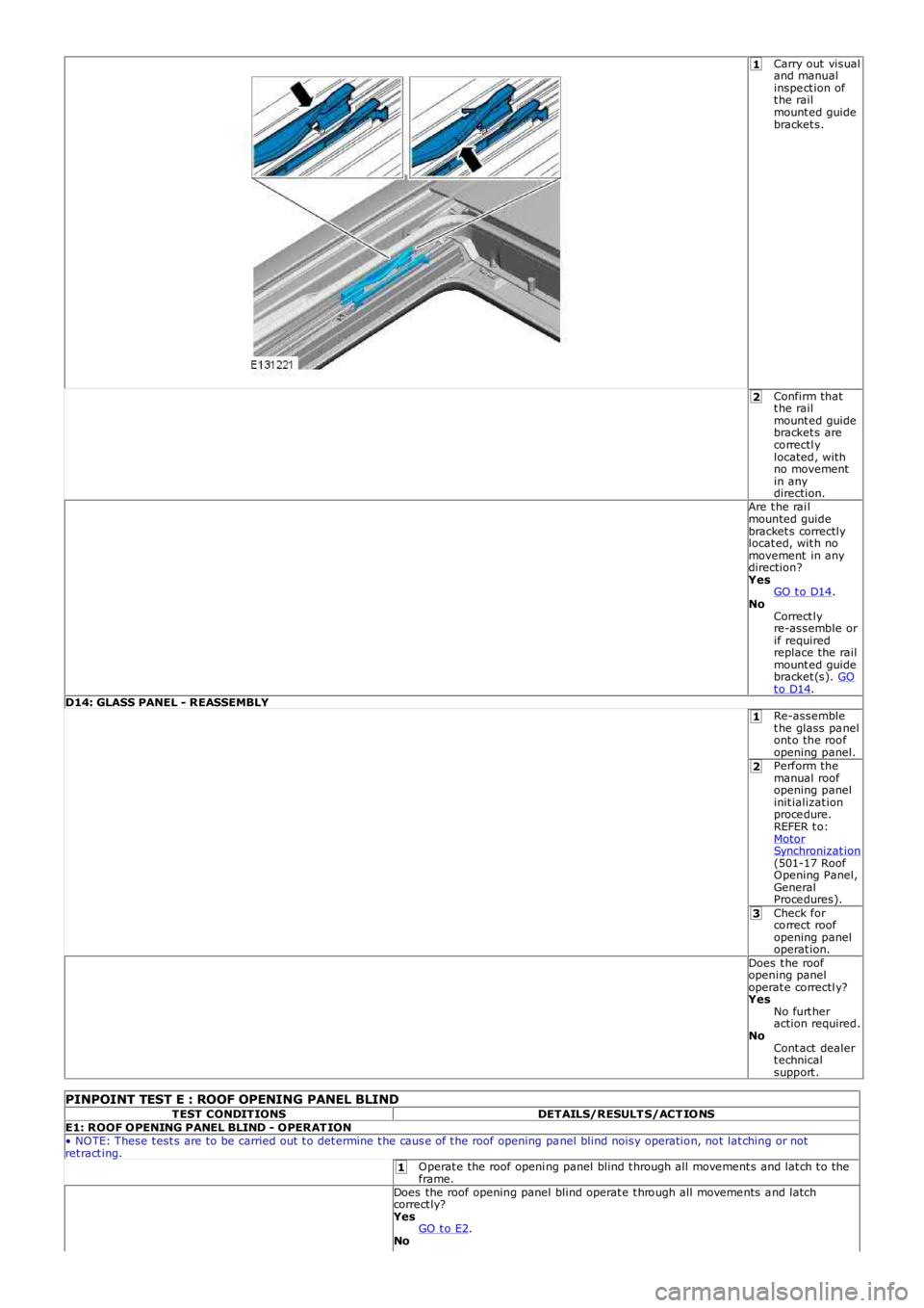
Carry out visualand manualinspe ct ion oft he railmount ed guidebracket s.
Confirm thatt he railmount ed guidebracket s arecorrectl ylocated, withno movementin anydirection.Are t he rai lmounted guidebracket s correctlylocat ed, wit h nomovement in anydirection?YesGO t o D14.NoCorrect lyre-assemble orif requiredreplace the railmount ed guidebracket (s). GOt o D14.D14: GLASS PANEL - REASSEMBLYRe-assemblet he glass pa nelont o the roofopening panel.Perform themanual roofopening panelinit ializat ionproce dure.REFER t o:MotorSynchronizat ion(501-17 RoofOpening Panel,GeneralProce dures).Check forcorrect roofopening paneloperat ion.Does t he roofopening paneloperat e correctl y?YesNo furt heraction required.NoCont act dealert echnicalsupport .
PINPOINT TEST E : ROOF OPENING PANEL BLINDTEST CONDITIONSDETAILS/RESULT S/ACT IONSE1: ROOF OPENING PANEL BLIND - OPERAT ION• NOTE: These t est s are to be carried out t o det ermine t he caus e of t he roof opening pa nel blind noisy operation, not lat ching or notret ract ing.Operat e the roof openi ng panel blind t hrough all move ment s and lat ch t o theframe.Does the roof opening panel blind operat e t hrough all moveme nts a nd latchcorrect ly?YesGO t o E2.No
Page 2398 of 3229

4. Releas e the roof opening panel blind from the mount ing bracke t and remove the roof opening panel blind from the vehicl e.
1. Push the roof ope ning panel blind in t o the frame t o releas e t he left -hand spring axle .2. Rot at e the roof opening panel blind count er clockwis e.3. Remove t he roof ope ning panel blind.
4.
• NOTE: The roof ope ning panel must be rewound 7 rotat ions .
5. Rewind the roof opening panel.
1. Using a s uit able tool, hol d a nd rotat e t he spring axle.2. Push the spring axle in t o the roof ope ning panel blind and al ign the s pring axle locking holes .3. Using s uit able pin or paperclip (as illustrat ed), lock t he spring axle.
5.
• NOTE: Make sure t hat the s pring axle is correct ly located into t he roof opening panel frame.
• NOTE: Make sure t hat the s uit able pin or paperclip rema ins in place while ins talling t he roof opening pa nel blind.
6. Inst all the roof ope ning panel blind t o t he frame.
6.
Page 2400 of 3229
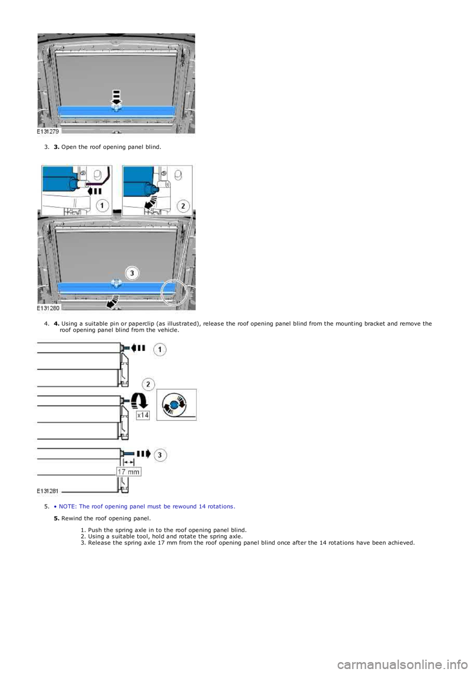
3. Open the roof opening panel blind.3.
4. Using a sui table pi n or paperclip (as illust rat ed), releas e the roof opening panel blind from t he mount ing bracket and remove theroof opening panel blind from the vehicle.4.
• NOTE: The roof ope ning panel must be rewound 14 rotat ions .
5. Rewind the roof opening panel.
1. Push the spring axle in t o the roof ope ning panel blind.2. Using a s uit able tool, hol d a nd rotat e t he spring axle.3. Rele ase t he spring axle 17 mm from t he roof opening pane l blind once aft er the 14 rot at ions have been achi eved.
5.
Page 2592 of 3229
Publis hed: 11-May-2011
Side Panel Sheet Metal Repairs - Side PanelRemoval and Installation
Removal
CAUTION: The side panel must be MIG slot brazed to its reinforcement, which contains DP600, (Dual Phase steel). MIG plug
w e lds / spot w e lds, must not be use d.
• NOTE: The side panel is serviced as a separate weld on panel, serviced less the fender mounting bracket, which is serviced
separately.
• NOTE: There are NVH elements attached inside this panel, they are not serviced on the new panel. If damaged, new element/s
will be required.
1. The s ide panel is replaced in conjunct ion wit h:
Front bumper cover
Front fender
Hood
Front door
Rear door
Quarter glass
Instrument panel
Windshield glass
Headliner
Rear bumper cover
2. For additional information relating to this repair procedure please
see the following:
Fo r a d d i t i o na l i nf o rma t i o n, re f e r t o : Body and Frame
(501-26 Body
Repairs - Vehicle Specific Information and Tolerance Checks,
Description and Operation) /
St a nd a rd W o rks ho p P ra ct i ce s
(100-00 General Informat ion,
Description and Operation).
3. Remove t he hood.
4. Remove the front fender.
5. Remove the front door.
Fo r a d d i t i o na l i nf o rma t i o n, re f e r t o : Front Door
(501-03 Body
Closures, Removal and Installation).
6. Remove t he rear door.
Fo r a d d i t i o na l i nf o rma t i o n, re f e r t o : Rear Door
(501-03 Body
Closures, Removal and Installation).
7. Remove the headliner.
Fo r a d d i t i o na l i nf o rma t i o n, re f e r t o : Headliner - Vehicles Without:
Tilting Roof Opening Panel (501-05 Int eri or Tri m and
Ornamentat ion, Removal and Inst all at ion) /
Headliner - Vehicles With: Tilting Roof Opening Panel
(501-05
Interior Trim and Ornamentation, Removal and Installation).
8. Re mo ve t he i ns t rume nt pa ne l .
Fo r a d d i t i o na l i nf o rma t i o n, re f e r t o : Inst rument Panel - TD4 2.2L
Di es e l (501-12 Inst rument Panel and Cons ole, Removal and
Installation).
9. Remove the windshield glass.
Fo r a d d i t i o na l i nf o rma t i o n, re f e r t o : Windshield Glass
(501-11
Glass, Frames and Mechanisms, Removal and Installation).
10. Remove the rear quarter glass.
Fo r a d d i t i o na l i nf o rma t i o n, re f e r t o : Rear Quarter Window Glass
(501-11 Glass, Frames and Mechanisms, Removal and Installation).
11. Re move t he re a r bumpe r co ve r.
Fo r a d d i t i o na l i nf o rma t i o n, re f e r t o : Rear Bumper Cover
(501-19
Bumpe rs , Re mo va l a nd I ns t a l l a t i o n).
12. Remove the upper and lower door hinges from the A-Pillar, 4 x
bolts.
13. Remove the upper and lower door hinges from the B-Pillar, 4 x
bolts.
14. Remove the front door striker from the B-Pillar.
15. Remove the rear door striker from the C-Pillar.
16. Remove the roof moulding, front and rear sect ions .
17. Re mo ve t he s i d e a i r curt a i n mo d ul e .
Fo r a d d i t i o na l i nf o rma t i o n, re f e r t o : Si d e A i r Curt a i n Mo d ul e
(501-20B Supplement al Res t raint Syst em, Removal and
Page 2600 of 3229
Publ is hed: 11-May-2011
Side Panel Sheet Metal Repairs - Side Panel Front Section
Removal and Installation
Removal
CAUTION: The side panel front section must be MIG slot brazed to its reinforcement, which contains DP600, (Dual
Phase steel). MIG plug we lds / spot w elds, must not be use d.
• NOTE: The side panel front section is serviced as a separate weld on panel, serviced less the fender mounting bracket,
which is serviced separately.
• NOTE: There are NVH elements attached inside this panel, they are not serviced on the new panel. If damaged, new
element/s will be required.
1. The s ide panel front s ect ion is replaced in conjunct ion wit h:
Front bumper cover
Front fender
Hood
Front door
Rear door
Instrument panel
Windshield glass
Headliner
2. Fo r a d d i t i o na l i nf o rma t i o n re l a t i ng t o t hi s re p a i r p ro ce d ure
please see the following:
Fo r a d d i t i o na l i nf o rma t i o n, re f e r t o : Body and Frame
(501-26
Body Repairs - Vehicle Specific Information and Tolerance
Checks, Description and Operation) /
St a nd a rd W o rks ho p P ra ct i ce s
(100-00 Ge ne ra l I nf o rma t i o n,
Description and Operation).
3. Remove the hood.
4. Remove the front fender.
5. Remove the front door.
Fo r a d d i t i o na l i nf o rma t i o n, re f e r t o : Front Door
(501-03 Body
Closures, Removal and Installation).
6. Remove the rear door.
Fo r a d d i t i o na l i nf o rma t i o n, re f e r t o : Rear Door
(501-03 Body
Closures, Removal and Installation).
7. Remove the headliner.
Fo r a d d i t i o na l i nf o rma t i o n, re f e r t o : Headliner - Vehicles
Without: Tilting Roof Opening Panel (501-05 Int eri or Tri m and
Ornamentation, Removal and Installation) /
Headliner - Vehicles With: Tilting Roof Opening Panel
(501-05
Int erior Trim and Ornamentat ion, Removal and Installat ion).
8. Re move t he i ns t rume nt pa ne l .
Fo r a d d i t i o na l i nf o rma t i o n, re f e r t o : Instrument Panel - TD4
2.2L Di es el (501-12 Ins t rument Panel and Cons ole, Removal
and Installation).
9. Remove the windshield glass.
Fo r a d d i t i o na l i nf o rma t i o n, re f e r t o : Windshield Glass
(501-11
Glass, Frames and Mechanisms, Removal and Installation).
10. Remove the upper and lower door hinges from the A-Pillar, 4
x bol t s .
11. Remove the upper and lower door hinges from the B-Pillar, 4
x bol t s .
12. Remove the front door striker from the B-Pillar.
13. Re mo ve t he s i d e a i r curt a i n mo d ul e .
Fo r a d d i t i o na l i nf o rma t i o n, re f e r t o : Si d e A i r Curt a i n Mo d ul e
(501-20B Suppl ement al Res t rai nt Sys t em, Removal and
Installation).
14. Remove the rear seat cushion.
Fo r a d d i t i o na l i nf o rma t i o n, re f e r t o : Rear Seat Cushion
(501-10
Seating, Removal and Installation).
15. Remove the RH & LH rocker panel inner trims.
16. Remove the B-Pillar side impact sensor.
Fo r a d d i t i o na l i nf o rma t i o n, re f e r t o : B-Pillar Side Impact Sensor
Page 2601 of 3229
(501-20B Suppl ement al Res t rai nt Sys t em, Removal and
Installation).
17. Remove the front safety belt retractor.
Fo r a d d i t i o na l i nf o rma t i o n, re f e r t o : Front Safety Belt Retractor
(501-20A Safe t y Bel t Sys t em, Removal and Ins t al l at i on).
18. Release and lay aside the front carpet section.
19. Re mo ve t he re a r ca rp e t s e ct i o n.
20. Remove the roof moulding, front and rear sections.
21. Remove the front wheel and tire.
Fo r a d d i t i o na l i nf o rma t i o n, re f e r t o : Wheel and Tire
(204-04
Wheels and Tires, Removal and Installation).
22. Remove the rocker panel outer moulding.
23. Release and lay aside the insulating material at the inner
bulkhead.
24. Release and lay aside the wiring harnesses at the A-Pillar,
B-Pillar and rocker panel.
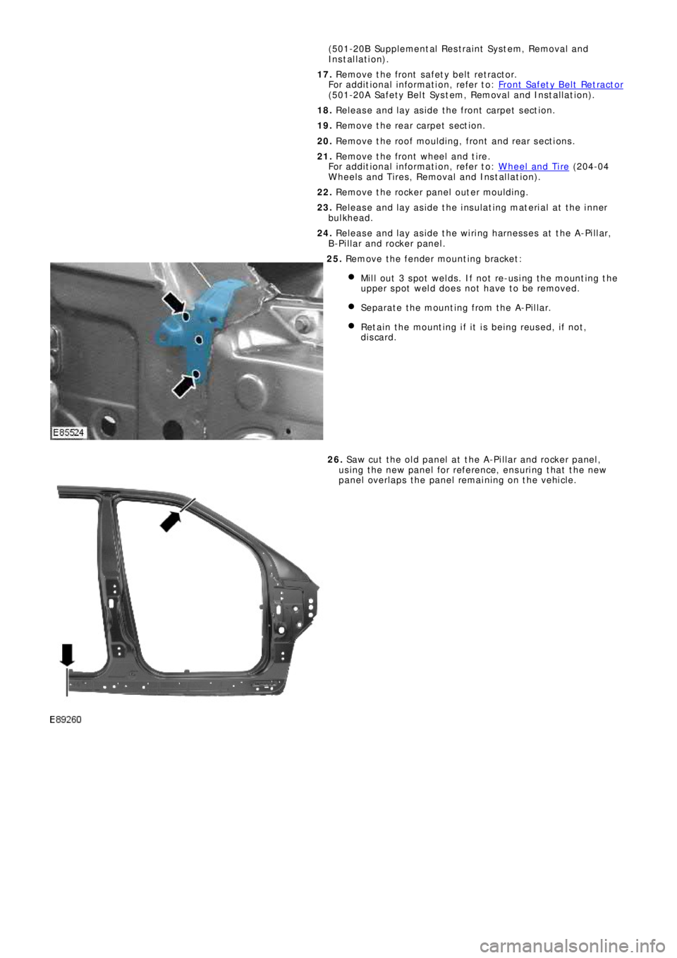
25. Remove the fender mounting bracket:
Mil l out 3 s pot welds . If not re-us i ng t he mount ing t he
upper spot weld does not have to be removed.
Separate the mounting from the A-Pillar.
Retain the mounting if it is being reused, if not,
discard.
26. Saw cut the old panel at the A-Pillar and rocker panel,
us i ng t he ne w p a ne l f o r re f e re nce , e ns uri ng t ha t t he ne w
panel overlaps the panel remaining on the vehicle.
Page 2607 of 3229
Publ is hed: 11-May-2011
Side Panel Sheet Metal Repairs - A-Pillar Outer Panel
Removal and Installation
Removal
CAUTION: The A-Pillar outer panel must be MIG slot brazed to the reinforcement, which is DP600, (Dual Phase steel).
MIG plug we lds / spot we lds, must not be used.
• NOTE: The A-Pillar outer panel is serviced as a separate weld-on panel. The fender mounting bracket is serviced
separately.
• NOTE: There are NVH elements attached inside this panel; they are not serviced on the new panel. If damaged, new
element(s) will be required.
1. The A-Pillar out er panel is replaced in conjunct ion wit h:
Front bumper cover
Hood
Front fender
Front door
Instrument panel
Windshield glass
Headliner
2. Fo r a d d i t i o na l i nf o rma t i o n re l a t i ng t o t hi s re p a i r p ro ce d ure
please see the following:
Fo r a d d i t i o na l i nf o rma t i o n, re f e r t o : Body and Frame
(501-26
Body Repairs - Vehicle Specific Information and Tolerance
Checks, Description and Operation) /
St a nd a rd W o rks ho p P ra ct i ce s
(100-00 Ge ne ra l I nf o rma t i o n,
Description and Operation).
3. Remove the hood.
4. Remove the front fender.
5. Remove the front door.
Fo r a d d i t i o na l i nf o rma t i o n, re f e r t o : Front Door
(501-03 Body
Closures, Removal and Installation).
6. Remove the headliner.
Fo r a d d i t i o na l i nf o rma t i o n, re f e r t o : Headliner - Vehicles
Without: Tilting Roof Opening Panel (501-05 Int eri or Tri m and
Ornamentation, Removal and Installation) /
Headliner - Vehicles With: Tilting Roof Opening Panel
(501-05
Int erior Trim and Ornamentat ion, Removal and Installat ion).
7. Re move t he i ns t rume nt pa ne l .
Fo r a d d i t i o na l i nf o rma t i o n, re f e r t o : Instrument Panel - TD4
2.2L Di es el (501-12 Ins t rument Panel and Cons ole, Removal
and Installation).
8. Remove the windshield glass.
Fo r a d d i t i o na l i nf o rma t i o n, re f e r t o : Windshield Glass
(501-11
Glass, Frames and Mechanisms, Removal and Installation).
9. Remove t he upper and l ower door hi nges from t he pi l lar, 4 x
bolts.
10. Re mo ve t he ro cke r p a ne l i nne r t ri m.
11. Re mo ve t he s i d e a i r curt a i n mo d ul e .
Fo r a d d i t i o na l i nf o rma t i o n, re f e r t o : Si d e A i r Curt a i n Mo d ul e
(501-20B Suppl ement al Res t rai nt Sys t em, Removal and
Installation).
12. Remove the front wheel and tire.
Fo r a d d i t i o na l i nf o rma t i o n, re f e r t o : Wheel and Tire
(204-04
Wheels and Tires, Removal and Installation).
13. Remove the rocker panel outer moulding.
14. Release and lay aside the front carpet section.
15. Re mo ve t he re a r ca rp e t s e ct i o n.
16. Remove the roof moulding, front and rear sections.
17. Release and lay aside the wiring harness along the A-Pillar
i nne r a nd i nne r ro cke r p a ne l .
18. Release and lay aside the insulating material at the inner
bulkhead.
Page 2780 of 3229
Supplementary restraints system
60
L
Note: The location points of airbags fitted to
the vehicle are marked by the word AIRBAG
embossed into the trim.
Always contact your Land Rover
Dealer/Authorised repairer if :-
• An airbag inflates.
• The front or sides of the vehicle are
damaged.
• Any part of the SRS shows signs of
cracking or damage, including trim
covering airbags.
Airbag operation
Airbags cannot deploy co rrectly if they are
obstructed. Examples of obstructions are :-
• Any part of an occupa nts body in contact
with, or close to, an airbag cover. •
Objects placed on, or close to, an airbag
cover.
• Clothing, sun screens, or other material
hanging from grab handles.
• Clothing, cushions, or other material,
covering seat mounted airbags.
• Seat covers which are not approved by
Land Rover, or specifically designed for
use with seat mounted airbags.
This list is not exhaustive, and it remains the
responsibility of the driv er and passengers to
ensure that the airbags are not obstructed in
any way.
Deployment and deflation
In the event of a collision the airbag control
system monitors the ra te, and direction of
deceleration. If required to supplement the seat
belts, airbags will be deployed as appropriate.
Front airbags
The front passenger's, and driver's airbags are
able to deploy in two stages depending on the
severity of the frontal impact. In a severe
impact the airbags inflate fully to offer
maximum protection. In a lesser impact full
deployment is not require d, so the airbags are
partially inflated.
Side and curtain airbags
Side and curtain airbag s are designed to offer
increased protection for the torso and head in
a side impact. The curtain airbags deflate at a
slower rate than the front, or side airbags to
afford greater protection from serious head
injuries.
Phone systems should only be
installed by qualified persons familiar
with the operation of, and
requirements for, vehicles fitted with SRS. If
you are in any doubt, seek advice from your
Land Rover Dealer/Authorised repairer.
WARNINGS
For the airbags to operate correctly the
roof lining and door post trims must
be in good condition, correctly fitted,
and free from obstructi on. Any damage, wear,
or incorrect fitment shoul d be referred to your
Land Rover Dealer/Aut horised repairer as
soon as possible for ex amination and repair.
Do not allow passe ngers to obstruct
the operation of the airbags by placing
any part of their person, or any
objects, in contact with, or close to, an airbag
module. Airbags deploy at very high speeds,
and can cause serious inju ry or death if objects
or occupants are within the area of
deployment.
WARNINGS