2006 LAND ROVER FRELANDER 2 charging
[x] Cancel search: chargingPage 29 of 3229
Rear seat belt s
Side Curtain Airbag Modul es
CAUTION: If the head ai rbag modules are depl oyed, t he fol lowing component s mus t be replaced on the si de of thevehi cl e on whi ch the deployment occurred:
Side curt ain ai rbag modulesHeadl iner and all pil lar t ri msLink l ead bet ween airbag gas generat or and RCM harnes sAirbag ret aining cli psFront s eat bel t buckle pre-t ens i onersAny s ide i mpact s ens ors t hat have been phys i cal ly damaged or if a fault i s being regi st eredRCM
Additionally, the following items must be inspected for damage and replaced as necessary:
Component mount ing bracketsFront s eat bel ts , ret ractors and webbing, tongue lat chi ng functi on, 'D' l oop and body anchorage point sRear seat belt buckl es, webbing, buckle covers , t ongue l atching funct ion, and body anchorage point sAdjacent t rim componentsSeat bel t hei ght adjust ers
Rear impacts
CAUTION: If the s eat belt pre-tens ioners are deployed during a rear i mpact , the following component s mus t berepl aced:
Seat bel t pre-t ensi onersFront and rear s eat bel t ret ractors used during t he i mpactRCM
Additionally, the following items must be inspected for damage and replaced as necessary:
Seat bel t hei ght adjust ersFront s eat bel ts , ret ractors and webbing, tongue lat chi ng functi on, 'D' l oop and body anchorage point sRear seat belt buckl es, webbing, buckle covers , t ongue l atching funct ion, and body anchorage point s
Air Conditioning System Precautions
The air condi ti oni ng s yst em contai ns fl ui ds and components which coul d be pot ent ially hazardous to the s ervi ce engineeror the environment if not serviced and handl ed correctl y. The foll owing guideli nes are i ntended to alert t he s erviceengi neer t o pot ent ial s ources of danger and emphas is e t he i mport ance of ens uring t he i nt egri ty of t he Air Condit ioningoperati ng condi ti ons and component s i ns t alled to the vehicle.
W here neces s ary, addi ti onal s pecific precaut ions are det ail ed in t he relevant s ecti ons of t his Manual and als o in the Heal thand Safet y Sect ion. Thes e precauti ons mus t be referred to prior t o commenci ng repair operat ions .
The refri gerant us ed i n t he air condi ti oni ng s ys t em i s HFC-134a (Hydrofl uorocarbon) R134a.
• W ARNINGS:
Servi ci ng mus t onl y be carried out by pers onnel famil iar wit h bot h t he vehi cl e s ys tem and t he charging and t es ti ngequi pment. Al l operat ions mus t be carried out i n a wel l venti lat ed area away from open fl ame and heat sources .
R134a is a hazardous l iquid and when handl ed incorrect ly can caus e s erious injury. Sui table prot ect ive clot hi ng,cons is t ing of face protecti on, heat proof gloves, rubber boots and rubber apron or waterproof overal ls , mus t be worn whencarryi ng out operat ions on t he air condit ioning s ys tem.
Remedial act ions
W ARNING: Due to it s low evaporat ing t emperat ure, R134a must be handled wit h care. R134a spl as hed on any part oft he body will cause immedi ate freezing of t hat area. Als o, refrigerant cylinders and replenis hment t roll eys whendis charging wi ll freeze s ki n t o t hem if contact is made.
If an accident involving R134a s houl d occur, conduct t he followi ng remedi al acti ons :
If liquid R134a ent ers t he eye, do not rub i t. Gentl y run large quant it ies of eye wash over affected eye t o rai s e t het emperature. If an eye was h is not avail abl e, cool, clean wat er may be us ed t o fl ush the eye. Aft er ri nsi ng, covert he eye wit h a clean pad and s eek i mmediat e medical at t ent ion.If liquid R134a is s plas hed ont o t he s kin, run large quanti ti es of water over t he affected area to rais e thet emperature. Implement t he s ame acti on if t he s kin comes i n cont act wi th dis chargi ng cyl inders . W rap t hecont aminat ed body parts in bl ankets (or s imi lar mat eri al s ) and seek i mmediat e medical att ent ion.If the debil it at ing effect s of inhalati on of R134a vapour are s us pect ed, s eek fresh air. If t he affect ed pers on isuncons ci ous , move t hem away from t he cont aminated area t o fres h air and apply arti fici al respi rat ion and/or oxygenand s eek immedi at e medi cal at tenti on.
Service precauti ons
Obs erve t he fol lowing precaut ions when handl ing component s us ed in the ai r condit ioning s ys tem:
Page 30 of 3229
Air condi ti oning unit s mus t not be li ft ed by t hei r hos es , pipes or capil lary li nes .Hos es and lines mus t not be s ubjected t o any t wis t or s tress ; t he efficiency of the s ys tem wil l be impai red by ki nksor res trict ions. Make s ure that hos es are correct ly pos it ioned before t ightening coupli ngs , and make s ure that allclips and support s are ut il is ed.Flexible hos es s houl d not be pos it ioned cl oser t han 100 mm (4.0 i n) t o t he exhaus t manifold unl es s protected byheat shi el ding.Complet ed ass embli es mus t be checked for refrigerat ion l ines t ouching met al panels . Any direct contact ofcomponents and panels may t rans mit nois e and s o must be el iminated.The appropri at e t orque wrench must be us ed when t ight eni ng refri gerant connect ions to t he s ti pul at ed value. Anaddi ti onal s panner mus t be us ed t o hold t he union t o prevent t wis ti ng of the pi pe when t ightening connect ions .Before connecti ng any hos e or pipe, make s ure that refri gerant oil is appli ed t o t he seat of t he new O-ri ngs , BUTNOT to the t hreads of the connect ion.All prot ect ive pl ugs or caps mus t remai n i n place in the component unt il i mmediat el y pri or to connect ion.Make s ure component s are at room temperat ure before uncappi ng/unpl uggi ng, t o prevent condens at ion of moi s turefrom the ai r that enters it .W hen di sconnect ing, immedi ately pl ug or cap all air condi ti oni ng pipes t o prevent ingres s of dirt and mois t ure i ntot he sys t em.Component s mus t not remain uncapped/unpl ugged, if a sys t em has been left uncapped/unpl ugged for 20 mi nut esor longer, a new recei ver/drier mus t be i ns t alled.The receiver/dri er contai ns des i ccant which absorbs mois t ure. It must be pos it ively sealed at al l ti mes . Areceiver/dri er t hat has been left uncapped for longer t han 20 mi nutes mus t not be used; i nst all a new uni t.The receiver/dri er s hould be the l ast component connect ed to the sys tem t o make s ure opt imum dehydrat ion andmaximum moi st ure protecti on of the sys tem.W henever a component of t he refrigerat ion s yst em is repl aced, it will al so be neces sary t o ins t al l a newreceiver/dri er uni t.Us e alcohol and a cl ean li nt -free cl oth to cl ean di rt y connecti ons.Make s ure t hat all new part s i ns t alled are marked for us e wit h R134a.W hen a major repai r has been complet ed, a leak t es t s hould be conduct ed; refer t o t he Repai rs Secti on of thi smanual for the correct procedure.
Refrigerant oil
CAUTION: Refrigerant oil eas il y absorbs water and mus t not be s tored for long periods. Do not pour unusedrefri gerant oi l back i nto the container. Always use an approved refrigerant oi l.
W hen replaci ng component s in the ai r condit ioning s ys tem, drai n t he refri gerant oi l from t he component being replacedint o a graduat ed cont ainer. On as s embly, add t he quant it y of refri gerant oi l drained t o t he new component - See Ai rCondi ti oni ng Compres s or Repl acement in this Sect ion.
Compres s or
A new compress or is sealed and press uris ed wit h Ni trogen gas . W hen i nst all ing a new compres sor, sl owly releas e thes eal ing cap; gas pres sure s houl d be heard to vent as t he s eal i s broken.
CAUTION: A new compress or s houl d always be s ealed and could be pres suris ed wit h ni trogen gas . To avoid pos si bleoil l os s , rel eas e t he s ealing cap(s ) s lowl y. Do not remove t he cap(s ) unt il i mmediatel y pri or to connect ing t he aircondi ti oni ng pipes t o the compress or.
Rapid refrigerant dis charge
If the ai r condit ioning s ys tem is i nvol ved in accident damage and t he s yst em is punct ured, t he refri gerant will di schargerapi dl y. The rapid di scharge of refrigerant wil l als o res ult in t he los s of mos t of the oi l from t he s yst em. The compres sormus t be removed and al l the remaining oi l in t he compres s or drained and refil led as i nst ruct ed in t he air condit ionings ect ion of t his manual.
Precaut ions for refrigerant recovery, recycl ing and rechargi ng
W hen t he air condit ioning s yst em is recharged, any exi s ti ng refri gerant i s first recovered from t he s ys t em and recycled.The s ys t em i s t hen charged wit h the required weight of refrigerant and volume of refrigerant oil .
W ARNING: Refri gerant mus t al ways be recycl ed before reus e t o make s ure that the purit y of the refrigerant i s highenough for s afe us e i n the ai r condit ioni ng sys t em. Recycl ing s hould al ways be carried out wit h equipment which i s des i gncert ifi ed by Underwrit er Laborat ory Inc. for compl iance wit h SAE J1991. Ot her equipment may not recycle refrigerant t o t herequired level of purit y.
• CAUTIO NS:
A R134a Refri gerant Recovery Recycli ng Rechargi ng Stat ion mus t not be us ed wit h any ot her t ype of refrigerant .Refrigerant R134a from domes ti c and commercial s ources mus t not be used i n mot or vehi cl e air condi ti oni ng s yst ems .
The s yst em must be evacuat ed i mmediat el y before recharging commences. Del ay bet ween evacuati on and rechargingis not permit ted.
Air Condit ioning Compress or Repl acement
A new compress or is suppli ed fi ll ed wit h a full charge (X cm³) of refrigerant oi l.
A calculat ed quant it y of oil mus t be drai ned from t he new compres s or before i nst all ing. To cal cul at e t he quant it y of oil t obe drai ned:
Remove the drain pl ug from the ol d compres sor.
Page 35 of 3229
Any s praying s houl d preferably be carri ed out in venti lat ed boot hs which i ncorporat e faci li ti es for removi ng vapors ands pray dropl et s from the breathing zone.
W ear appropri at e gl oves , eye and res pirat ory protecti on.
Antifreeze
May be flammabl e when undilut ed.
Vapors may be gi ven off from coolant anti freeze when heat ed. Avoid breathi ng thes e vapors .
Anti freeze may be absorbed through t he s kin i n t oxi c or harmful quanti ti es. Ant ifreeze, i f s wal lowed, can be fat al; SEEKIMMEDIAT E MEDICAL AT T ENT ION.
Battery Acids
See als o Al kal is and Acids .
Gas es releas ed duri ng bat t ery charging are expl osi ve. Al ways remove t he batt ery from t he vehi cl e pri or to chargi ng. Neverus e naked flames or al low s parks near charging or recentl y charged bat t eries . NEVER add aci d t o a bat tery, t he chemicalreacti on produced wil l be vi olent and expl os i ve. In cases of eye contact, was h affected area wit h copious amount s of wat erand SEEK IMMEDIAT E MEDICAL AT T ENT ION.
Make s ure t here i s adequat e vent il ati on during bat tery charging, obs erve NO SMOKING POLICY .
Brake Pads and Linings
Always fit t he correct grade and s peci fi cat ion of brake pads and l inings . W hen renewi ng pads and lini ngs , always repl aceas complete axl e s ets .
Brake and Clutch Fluid
Splas hes to t he s kin and eyes are irri tat ing and i n t he long t erm can be damagi ng, avoid prolonged s ki n cont act. In casesof eye cont act , wash affect ed area wi th copious amount s of water and SEEK IMMEDIATE MEDICAL ATTENTION.
Chemical Materials
All chemical materials should al ways be used wit h caut ion and st ored and handled wi th care. They may be toxic, harmful,corros ive, irri tant or highly fl ammable and gi ve ri se to hazardous fumes and dus t s.
The effect s of exces s ive expos ure to chemi cal s may be i mmediat e or delayed; briefl y experienced or permanent ;cumulati ve; s uperficial; life t hreatening; or may reduce l ife expect ancy.
Chemical Materials - Do's
Do careful ly read and observe hazard and precaut ion warnings given on material cont ai ners (labels ) and in anyaccompanyi ng leaflets , pos ters or ot her ins truct ions . Material heal th and safet y data s heet s can be obtained frommanufacturers .Do remove chemi cal mat eri al s from the s kin and cl othing as soon as pract icable after s oil ing. Change heavily soi ledclothi ng and have it cleaned.Do organi se work pract ices and prot ect ive clot hing t o avoi d s oil ing of t he s ki n and eyes .Do avoid breat hing vapors , aeros ols , dus t s or fumes ; inadequat e container labell ing; fi re and expl os i on hazards .Do was h before job breaks, before eati ng, s moking, dri nki ng or usi ng t oi let faci lit ies when handli ng chemicalmat erial s.Do keep work areas clean, unclut tered and free of s pi ll s.Do s t ore chemical materials according to nat ional and local regul at ions .Do keep chemical materi als out of t he reach of chi ldren.
Chemical Materials - Do Not
Do Not mi x chemical materials except under the manufact urers ins truct ions ; s ome chemicals can form ot her toxic orharmful chemi cal s, gi ve off t oxi c or harmful fumes or become explos ive when mixed t oget her.Do Not s pray chemical materials , part icularly t hose bas ed on s olvents , i n confined spaces , for example when peopleare ins ide a vehicle.Do Not apply heat or fl ame t o chemical materi als except under the manufact urers ins truct ions . Some are hi ghlyfl ammable and some may rel ease toxic or harmful fumes .Do Not l eave contai ners open. Fumes given off can bui ld up to t oxic, harmful or explos ive concentrati ons . Somefumes are heavier than ai r and wil l accumulate in confi ned areas s uch as pi ts .Do Not t rans fer chemical materi als t o unlabell ed cont ainers .Do Not clean hands or cl othing wit h chemicals . Chemical s , parti cul arly sol vent s and fuel s, wi ll dry ski n and maycaus e i rrit ati on leading t o dermat it is or be abs orbed t hrough t he s ki n i n t oxi c or harmful quanti ti es .Do Not us e empt ied containers for ot her mat eri al s except when t hey have been cleaned under s upervis edcondi ti ons .Do Not s niff or smel l chemi cal mat eri al s , even brief expos ure to hi gh concentrat ions of fumes can be toxic orharmful.
Corrosion Protection Materials
Some corrosi on prot ect ion mat eri als are highly flammabl e – obs erve NO SMOKING POLICY.
Thes e materials are vari ed and the manufact urers ins truct ions mus t always be foll owed. The mat eri als may contai ns olvent s , res ins or petroleum product s. Skin and eye cont act s houl d be avoided. They s hould only be s prayed in condit ionsof adequate vent il at ion and not i n confined s paces .
Page 64 of 3229
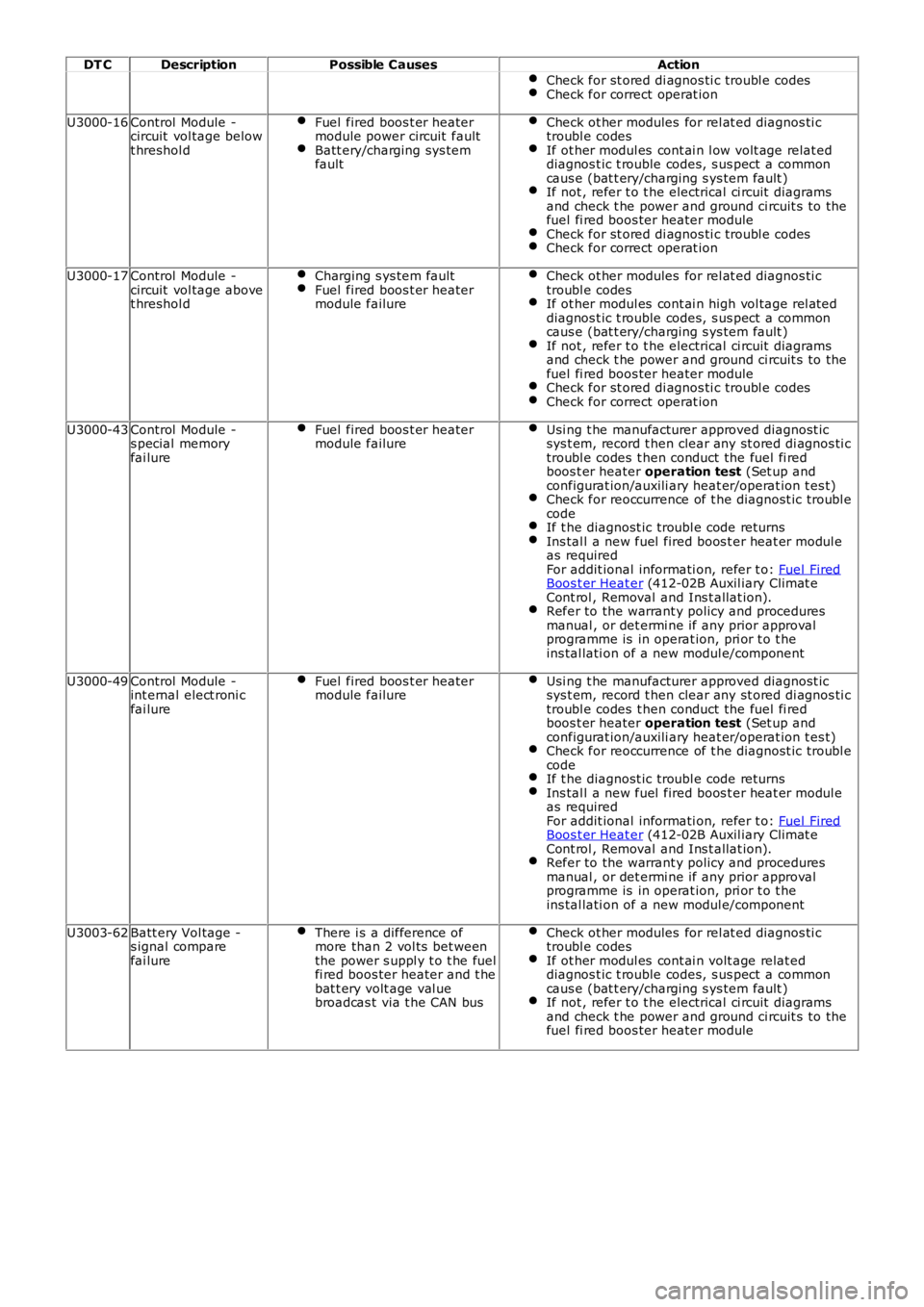
DT CDescriptionPossible CausesAction
Check for st ored di agnos ti c troubl e codesCheck for correct operat ion
U3000-16Control Module -circuit vol tage belowt hreshol d
Fuel fired boos t er heatermodule power circuit faultBatt ery/charging sys temfault
Check ot her modules for rel at ed diagnos ti ctroubl e codesIf ot her modul es cont ai n l ow volt age relat eddiagnos t ic t rouble codes, s us pect a commoncaus e (bat t ery/charging s ys tem fault )If not , refer t o t he electrical ci rcuit diagramsand check t he power and ground ci rcuit s to thefuel fi red boos ter heater moduleCheck for st ored di agnos ti c troubl e codesCheck for correct operat ion
U3000-17Control Module -circuit vol tage abovet hreshol d
Charging s ys tem faultFuel fired boos t er heatermodule failure
Check ot her modules for rel at ed diagnos ti ctroubl e codesIf ot her modul es cont ai n high vol tage rel ateddiagnos t ic t rouble codes, s us pect a commoncaus e (bat t ery/charging s ys tem fault )If not , refer t o t he electrical ci rcuit diagramsand check t he power and ground ci rcuit s to thefuel fi red boos ter heater moduleCheck for st ored di agnos ti c troubl e codesCheck for correct operat ion
U3000-43Control Module -s pecial memoryfai lure
Fuel fired boos t er heatermodule failureUsi ng t he manufacturer approved diagnost icsys t em, record t hen clear any st ored di agnos ti ctroubl e codes t hen conduct the fuel fi redboos t er heater operation test (Set up andconfigurat ion/auxili ary heat er/operat ion t es t)Check for reoccurrence of t he diagnost ic troubl ecodeIf t he diagnost ic troubl e code returnsIns tal l a new fuel fired boos t er heat er modul eas requiredFor addit ional informati on, refer t o: Fuel FiredBoos t er Heat er (412-02B Auxil iary Climat eCont rol , Removal and Ins t allat ion).Refer to the warrant y policy and proceduresmanual , or det ermi ne if any prior approvalprogramme is in operat ion, pri or t o t heins tal lati on of a new modul e/component
U3000-49Control Module -int ernal elect roni cfai lure
Fuel fired boos t er heatermodule failureUsi ng t he manufacturer approved diagnost icsys t em, record t hen clear any st ored di agnos ti ctroubl e codes t hen conduct the fuel fi redboos t er heater operation test (Set up andconfigurat ion/auxili ary heat er/operat ion t es t)Check for reoccurrence of t he diagnost ic troubl ecodeIf t he diagnost ic troubl e code returnsIns tal l a new fuel fired boos t er heat er modul eas requiredFor addit ional informati on, refer t o: Fuel FiredBoos t er Heat er (412-02B Auxil iary Climat eCont rol , Removal and Ins t allat ion).Refer to the warrant y policy and proceduresmanual , or det ermi ne if any prior approvalprogramme is in operat ion, pri or t o t heins tal lati on of a new modul e/component
U3003-62Batt ery Vol tage -s ignal comparefai lure
There i s a difference ofmore than 2 vol ts bet weenthe power s uppl y t o t he fuelfi red boos ter heater and t hebat t ery volt age val uebroadcas t via t he CAN bus
Check ot her modules for rel at ed diagnos ti ctroubl e codesIf ot her modul es cont ai n volt age relat eddiagnos t ic t rouble codes, s us pect a commoncaus e (bat t ery/charging s ys tem fault )If not , refer t o t he electrical ci rcuit diagramsand check t he power and ground ci rcuit s to thefuel fi red boos ter heater module
Page 102 of 3229
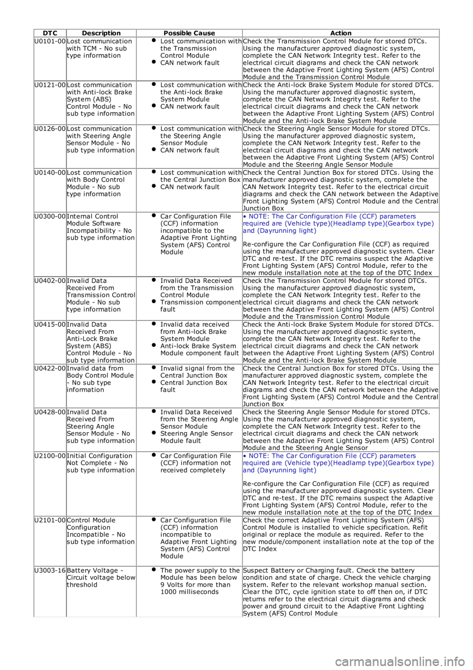
DT CDescriptionPossible CauseAction
U0101-00Lost communicat ionwit h TCM - No s ubt ype i nformati on
Los t communi cat ion wi tht he Trans mis s ionControl Modul eCAN net work fault
Check t he Trans mis s ion Cont rol Module for st ored DTCs .Us ing t he manufacturer approved diagnost ic sys tem,compl ete the CAN Net work Int egrit y t est . Refer t o theelectrical ci rcuit diagrams and check t he CAN networkbet ween t he Adapt ive Front Li ght ing Sys tem (AFS) ControlModul e and t he Trans mis s ion Cont rol Modul eU0121-00Lost communicat ionwit h Ant i-lock BrakeSyst em (ABS)Control Module - Nos ub type i nformati on
Los t communi cat ion wi tht he Anti -l ock BrakeSys tem Modul eCAN net work fault
Check t he Anti -l ock Brake Sys t em Module for s tored DTCs.Us ing t he manufacturer approved diagnost ic sys tem,compl ete the CAN Net work Int egrit y t est . Refer t o theelectrical ci rcuit diagrams and check t he CAN networkbet ween t he Adapt ive Front Li ght ing Sys tem (AFS) ControlModul e and t he Anti -l ock Brake Sys t em ModuleU0126-00Lost communicat ionwit h St eering Angl eSens or Module - Nos ub type i nformati on
Los t communi cat ion wi tht he Steering AngleSensor ModuleCAN net work fault
Check t he Steering Angle Sens or Modul e for s t ored DTCs .Us ing t he manufacturer approved diagnost ic sys tem,compl ete the CAN Net work Int egrit y t est . Refer t o theelectrical ci rcuit diagrams and check t he CAN networkbet ween t he Adapt ive Front Li ght ing Sys tem (AFS) ControlModul e and t he Steeri ng Angle Sens or Module
U0140-00Lost communicat ionwit h Body ControlModule - No subt ype i nformati on
Los t communi cat ion wi tht he Central Junct ion BoxCAN net work fault
Check t he Central Junct ion Box for s tored DTCs . Us ing themanufacturer approved diagnost ic sys tem, complet e t heCAN Net work Integri ty tes t. Refer t o t he electrical ci rcuitdiagrams and check the CAN network bet ween t he Adapt iveFront Lighti ng Sys t em (AFS) Cont rol Modul e and t he CentralJuncti on Box
U0300-00Int ernal Cont rolModule Soft wareIncompati bili ty - Nos ub type i nformati on
Car Configurat ion Fi le(CCF) i nformati oni ncompati ble t o t heAdapti ve Front Li ghti ngSys tem (AFS) Cont rolModule
• NOTE: The Car Configurat ion Fil e (CCF) parametersrequired are (Vehicle type)(Headl amp t ype)(Gearbox t ype)and (Dayrunning light )
Re-configure the Car Confi gurati on Fil e (CCF) as requi redusi ng t he manufact urer approved diagnost ic s ys tem. Cl earDTC and re-t es t . If t he DTC remains s us pect t he Adapt iveFront Lighti ng Sys t em (AFS) Cont rol Modul e, refer t o t henew module ins tall ati on not e at t he t op of the DTC IndexU0402-00Invali d Dat aRecei ved FromTrans mis s ion Cont rolModule - No subt ype i nformati on
Inval id Dat a Recei vedfrom the Transmis si onControl Modul eTrans mi ss i on componentfaul t
Check t he Trans mis s ion Cont rol Module for st ored DTCs .Us ing t he manufacturer approved diagnost ic sys tem,compl ete the CAN Net work Int egrit y t est . Refer t o theelectrical ci rcuit diagrams and check t he CAN networkbet ween t he Adapt ive Front Li ght ing Sys tem (AFS) ControlModul e and t he Trans mis s ion Cont rol Modul eU0415-00Invali d Dat aRecei ved FromAnti -Lock BrakeSyst em (ABS)Control Module - Nos ub type i nformati on
Inval id dat a receivedfrom Anti -l ock BrakeSys tem Modul eAnt i-lock Brake Syst emModule component fault
Check t he Anti -l ock Brake Sys t em Module for s tored DTCs.Us ing t he manufacturer approved diagnost ic sys tem,compl ete the CAN Net work Int egrit y t est . Refer t o theelectrical ci rcuit diagrams and check t he CAN networkbet ween t he Adapt ive Front Li ght ing Sys tem (AFS) ControlModul e and t he Anti -l ock Brake Sys t em Module
U0422-00Invali d data fromBody Cont rol Module- No s ub t ypeinformat ion
Inval id s i gnal from theCentral Juncti on BoxCentral Juncti on Boxfaul t
Check t he Central Junct ion Box for s tored DTCs . Us ing themanufacturer approved diagnost ic sys tem, complet e t heCAN Net work Integri ty tes t. Refer t o t he electrical ci rcuitdiagrams and check the CAN network bet ween t he Adapt iveFront Lighti ng Sys t em (AFS) Cont rol Modul e and t he CentralJuncti on Box
U0428-00Invali d Dat aRecei ved FromSteering AngleSens or Module - Nos ub type i nformati on
Inval id Dat a Recei vedfrom the St eeri ng Angl eSensor ModuleSt eering Angle Sens orModule fault
Check t he Steering Angle Sens or Modul e for s t ored DTCs .Us ing t he manufacturer approved diagnost ic sys tem,compl ete the CAN Net work Int egrit y t est . Refer t o theelectrical ci rcuit diagrams and check t he CAN networkbet ween t he Adapt ive Front Li ght ing Sys tem (AFS) ControlModul e and t he Steeri ng Angle Sens or
U2100-00Ini ti al Configurat ionNot Complet e - Nos ub type i nformati on
Car Configurat ion Fi le(CCF) i nformati on notreceived complet ely
• NOTE: The Car Configurat ion Fil e (CCF) parametersrequired are (Vehicle type)(Headl amp t ype)(Gearbox t ype)and (Dayrunning light )
Re-configure the Car Confi gurati on Fil e (CCF) as requi redusi ng t he manufact urer approved diagnost ic s ys tem. Cl earDTC and re-t es t . If t he DTC remains s us pect t he Adapt iveFront Lighti ng Sys t em (AFS) Cont rol Modul e, refer t o t henew module ins tall ati on not e at t he t op of the DTC IndexU2101-00Control ModuleConfigurat ionIncompati ble - Nos ub type i nformati on
Car Configurat ion Fi le(CCF) i nformati oni ncompati ble t oAdapti ve Front Li ghti ngSys tem (AFS) Cont rolModule
Check t he correct Adapti ve Front Li ght ing Sys t em (AFS)Cont rol Module is i ns t alled to vehicle s pecificati on. Refitori gi nal or repl ace the modul e as required. Refer to thenew module/component ins tall ati on note at t he t op of theDTC Index
U3003-16Batt ery Vol tage -Circui t vol tage belowt hreshol d
The power s upply to theModule has been below9 Vol ts for more than1000 mi ll is econds
Sus pect Bat t ery or Charging fault . Check t he batt erycondit ion and st ate of charge. Check t he vehicle chargi ngs ys t em. Refer to the relevant workshop manual s ect ion.Clear the DTC, cycl e i gni ti on s tat e to off t hen on, i f DTCret urns refer to the el ect ri cal circui t diagrams and checkpower and ground ci rcuit t o t he Adapt ive Front Light ingSys t em (AFS) Cont rol Modul e
Page 103 of 3229
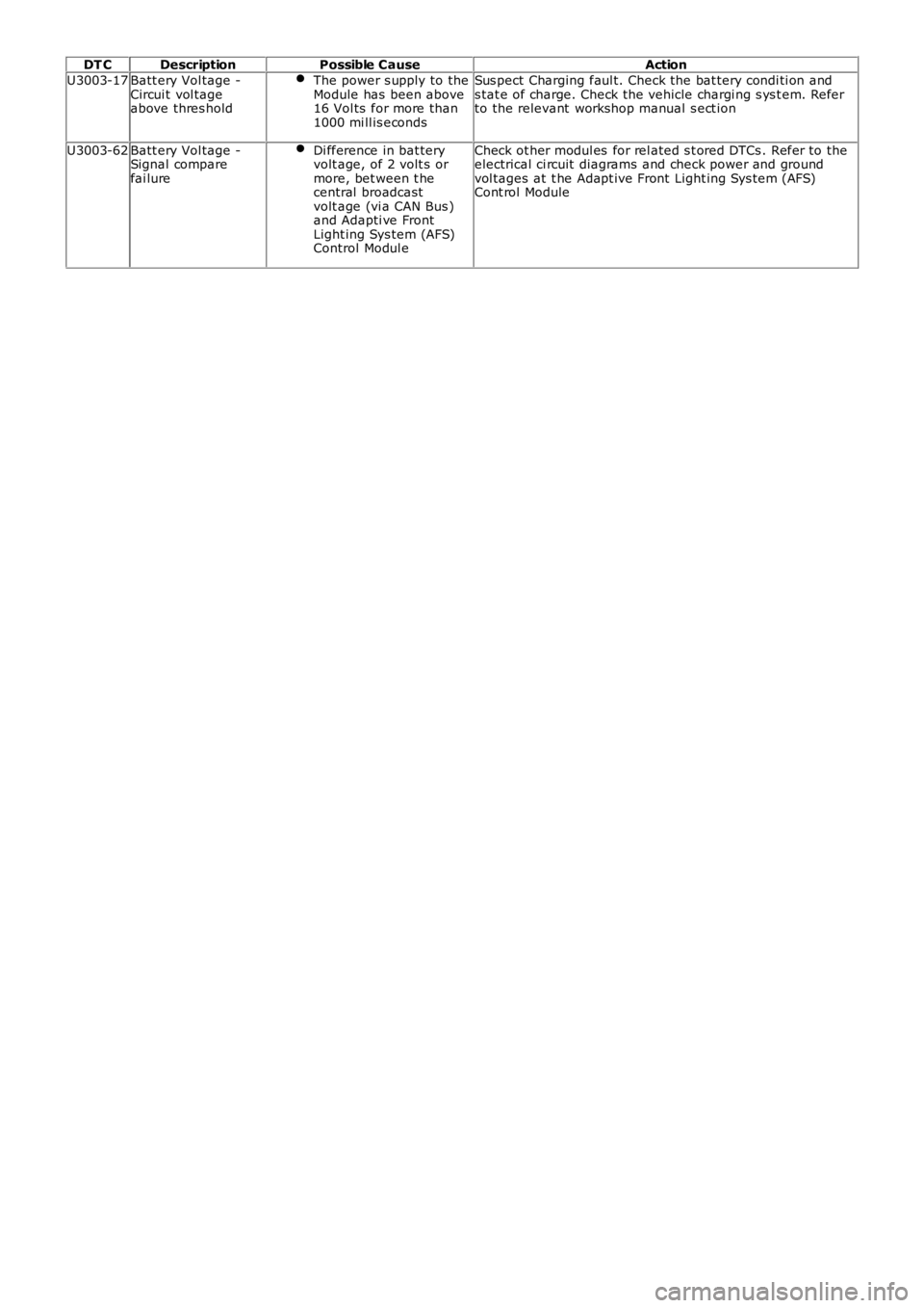
DT CDescriptionPossible CauseAction
U3003-17Batt ery Vol tage -Circui t vol tageabove thres hold
The power s upply to theModule has been above16 Vol ts for more than1000 mi ll is econds
Sus pect Charging faul t. Check the bat tery condi ti on ands tat e of charge. Check the vehicle chargi ng s ys t em. Referto the relevant workshop manual s ect ion
U3003-62Batt ery Vol tage -Signal comparefai lure
Di fference in bat teryvolt age, of 2 volt s ormore, bet ween t hecentral broadcastvolt age (vi a CAN Bus )and Adapti ve FrontLight ing Sys tem (AFS)Control Modul e
Check ot her modul es for rel ated s t ored DTCs . Refer to theelectrical ci rcuit diagrams and check power and groundvol tages at t he Adapt ive Front Light ing Sys tem (AFS)Cont rol Module
Page 141 of 3229
Publi s hed: 05-May-2011
General Information - Diagnostic Trouble Code (DTC) IndexDTC:
Transmission Control Module (TCM)
Des cript ion and Operat ion
• NOTE: If a cont rol module or component i s s uspect and the vehicl e remai ns under ma nufacturer warrant y, refer t o t he
W arranty Pol icy and Procedures manual (s ect ion B1.2), or determine i f any pri or appr oval program is i n operat ion, before
t he replacement of a component.
• NOTE: Generic scan t ool s may not read the codes li st ed, or may read only 5-digi t c odes . Match t he 5 digi ts from t he s can
t ool t o t he fi rs t 5 di gi ts of the 7-digit code li s ted t o i dent ify the fault (the las t 2 digi ts gi ve ext ra informati on read by the
manufacturer-approved di agnos ti c s ys t em).
• NOTE: W hen performing volt age or res is t ance t est s , always use a digi tal mult imeter (DMM) accurat e t o t hree deci mal
places, and wi th an up-t o-date cal ibrat ion cert ificate. W hen tes ti ng res is t ance al wa ys take t he res is t ance of t he DMM
leads i nt o account .
• NOTE: Check and recti fy bas ic faul ts before beginni ng diagnos t ic rout ines i nvol vi n g pinpoint t es t s.
• NOTE: Ins pect connect ors for s igns of water ingres s , and pins for damage and/or co rros ion.
• NOTE: If DTCs are recorded and, aft er performi ng the pi npoi nt tes ts , a fault is no t present , an int ermi tt ent concern may
be t he caus e. Always check for loose connect ions and corroded terminals .
Des cript ion And Operat ion
For a detail ed descripti on of the trans mi ss i on cont rol s ys t em, refer to t he relevant Des cript ion and O perati on sect ion i n the
works hop manual . For addit ional informat ion, refer t o: Trans mis s ion Des cript ion (307-01 Aut omati c
Trans mis s ion/Transaxle, Des cript ion and Operat ion).
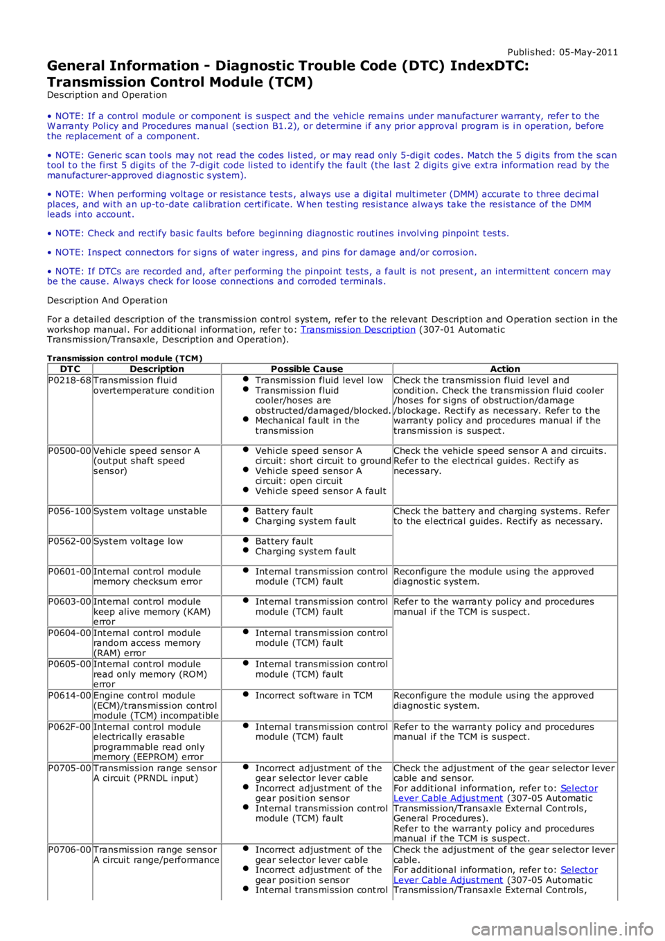
Transmission control module (TCM) DT C Description Possible Cause Action
P0218-68 Trans mis s ion flui d
overtemperat ure condit ion Transmis si on fluid level l ow Transmis si on fluid
cooler/hos es are
obs t ructed/damaged/blocked. Mechanical fault i n the
trans mi ss i on Check t he transmis s ion fluid level and
condit ion. Check t he t rans mis s ion flui d cool er
/hos es for s igns of obst ruct ion/damage
/blockage. Recti fy as necess ary. Refer t o t he
warrant y poli cy and procedures manual if t he
trans mi s si on is sus pect .
P0500-00 Vehi cle s peed s ens or A
(out put s haft s peed
s ens or) Vehi cl e s peed sens or A
ci rcuit : short ci rcuit t o ground Vehi cl e s peed sens or A
ci rcuit : open ci rcuit Vehi cl e s peed sens or A faul t Check t he vehi cl e s peed sens or A and circui ts .
Refer to the el ect ri cal guides . Rect ify as
neces sary.
P056-100 Sys t em volt age unst able Bat tery faul t Chargi ng s yst em fault Check t he batt ery and charging sys tems . Refer
to the el ect ri cal guides. Recti fy as neces sary.
P0562-00 Sys t em volt age low Bat tery faul t Chargi ng s yst em fault
P0601-00
Int ernal cont rol module
memory checksum error Int ernal t rans mi ss i on cont rol
modul e (TCM) fault Reconfi gure t he module us ing the approved
di agnos t ic s yst em.
P0603-00 Int ernal cont rol module
keep al ive memory (KAM)
error Int ernal t rans mi ss i on cont rol
modul e (TCM) fault Refer to the warrant y pol icy and procedures
manual i f the TCM is s us pect .
P0604-00 Int ernal cont rol module
random acces s memory
(RAM) error Int ernal t rans mi ss i on cont rol
modul e (TCM) fault P0605-00
Int ernal cont rol module
read only memory (ROM)
error Int ernal t rans mi ss i on cont rol
modul e (TCM) fault P0614-00
Engi ne cont rol module
(ECM)/t rans mi ss i on cont rol
module (TCM) incompati bl e Incorrect s oft ware i n TCM Reconfi gure t he module us ing the approved
di agnos t ic s yst em.
P062F-00 Int ernal cont rol module
electrically eras abl e
programmabl e read onl y
memory (EEPROM) error Int ernal t rans mi ss i on cont rol
modul e (TCM) fault Refer to the warrant y pol icy and procedures
manual i f the TCM is s us pect .
P0705-00 Trans mis s ion range sens or
A circui t (PRNDL i nput ) Incorrect adjus tment of t he
gear s elector lever cabl e Incorrect adjus tment of t he
gear posi ti on s ens or Int ernal t rans mi ss i on cont rol
modul e (TCM) fault Check t he adjus tment of t he gear s elector l ever
cable and sens or.
For addit ional informati on, refer t o: Sel ect or Lever Cabl e Adjus t ment (307-05 Aut omati c
Transmis s ion/Trans axle External Cont rols ,
General Procedures ).
Refer to the warrant y pol icy and procedures
manual i f the TCM is s us pect .
P0706-00 Trans mis s ion range sens or
A circui t range/performance Incorrect adjus tment of t he
gear s elector lever cabl e Incorrect adjus tment of t he
gear posi ti on s ens or Int ernal t rans mi ss i on cont rol Check t he adjus tment of t he gear s elector l ever
cable.
For addit ional informati on, refer t o: Sel ect or Lever Cabl e Adjus t ment (307-05 Aut omati c
Transmis s ion/Trans axle External Cont rols ,
Page 489 of 3229
Publi s hed: 11-May-2011
Power Brake Actuation - Brake Booster
Removal and Inst all ati on
Removal
• CAUTIO NS:
Extreme cleanli nes s mus t be exercis ed when handli ng thes e component s.
If brake fluid is s pil t on the pai ntwork, t he affect ed area must be immedi ately washed down wi th col d wat er.
All vehicles
1. W ARNING: Make sure t o s upport the vehicle wit h axles tands .
Rais e and s upport t he vehi cl e.
1.
Di sconnect t he bat t ery ground cable.
Refer t o: Specificati ons (414-00 Bat tery and Charging Sys tem -General Informat ion, Specificati ons).
2.
Remove t he winds hield wiper motor and l inkage.
Refer t o: W i nds hield W i per Mot or (501-16 W ipers and W as hers ,Removal and Ins tall ati on).
3.
Remove t he dri ver l ower ai r bag modul e.
Refer t o: Dri ver Lower Air Bag Module (501-20B SupplementalRes traint Sys t em, Removal and Inst all at ion).
4.
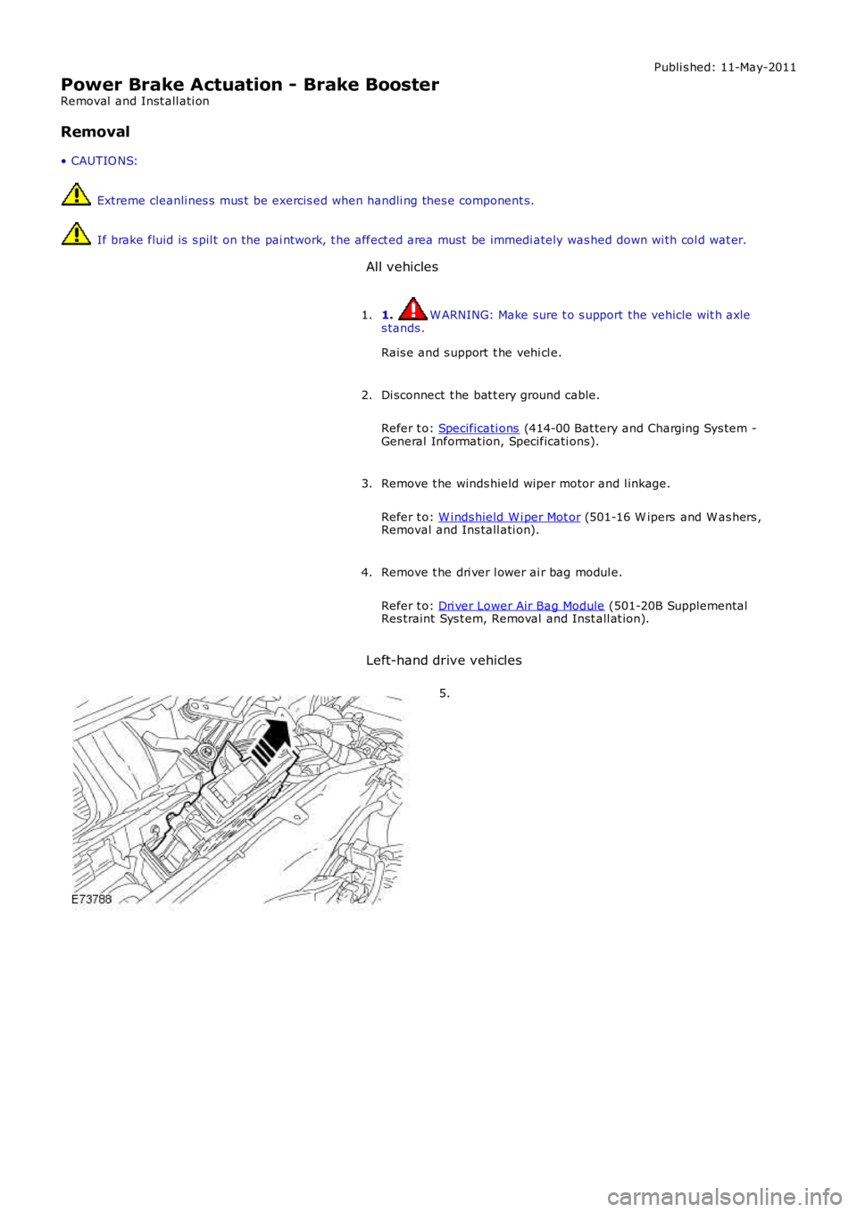
Left-hand drive vehicles
5.