Page 550 of 3229
Publi s hed: 11-May-2011
Power Steering - Power Steering Pressure TestI6 3.2L Petrol
General Procedures
Special T ool(s) 211-011-01
Valve Bl ock, Power Steeri ng Pres s ure Tes t 211-011-02
Hos e, Power St eering Press ure Tes t 211-011-11
Hos e, Power St eering Press ure Tes t 211-287
Hos e and Gauge, Power St eering Pres s ure Tes t 211-313
Adapter, Power St eering Press ure Tes t 211-325
Adapter, Power St eering Press ure Tes t
Di sconnect t he bat t ery ground cable.
Refer t o: Specificati ons (414-00 Bat tery and Charging Sys tem -
General Informat ion, Specificati ons).
1.
Remove t he air cleaner hous ing.
2.
Page 552 of 3229
Turn the s t eering full y lock-t o-l ock, s top t he engine.
Top-up t he power st eeri ng fl uid reservoi r.
For power s t eering press ures , refer to the s t eering s peci fi cat ion
s ect ion.
Refer t o: Specificati ons (211-02 Power Steering, Specificati ons ).
10.
11. CAUTION: Do not hold st eering at full l ock for longer t han
10 s econds .
W it h the engi ne at idle, s lowl y turn t he s teeri ng wheel and
hold on full l ock. Record t he pres s ure readi ng.11.
Repeat t he above procedure for t he other s ide. Record t he pres s ure readi ng.12.
W it h the engi ne at idle, rel ease the s t eering wheel. The press ure
s houl d be, at or bel ow, the pres s ure specified.
13.
Pres s ure out si de t hi s t olerance, i ndicat es a fault .
14.
15. CAUTION: Pump damage wi ll occur if t he t est valve is
clos ed for l onger peri ods .
To det ermi ne if t he fault is i n t he st eeri ng pump or the st eeri ng
rack, clos e the tes t val ve for a maxi mum of 5 s econds.
15.
If the press ures recorded fal l out s ide t he given values, replace the
power st eeri ng pump.
16.
If the maxi mum pump pres sure i s correct, t hen s uspect the power
s teering rack.
17.
18. CAUTION: Dis card flui d s iphoned from t he power st eeri ng
s yst em.
On compl et ion of t he t est s t op the engi ne, dis connect t he bat t ery
ground cable and s i phon t he fluid from t he power st eering res ervoir.
18.
Di sas s emble t he t es t equipment .
19.
Clean t he component mat ing faces . Inst all a new O-ring s eal.
Connect t he high-press ure pipe union t o t he power st eeri ng
pump. T orque:
25 Nm 20.
Inst all t he air cleaner hous ing.
Refer t o: Air Cleaner (303-12A Intake Ai r Dis tribut ion and Fil tering -
I6 3.2L Pet rol, Removal and Ins t al lat ion).
21.
Connect t he batt ery ground cable.
Refer t o: Specificati ons (414-00 Bat tery and Charging Sys tem -
General Informat ion, Specificati ons).
22.
Page 554 of 3229
Publi s hed: 11-May-2011
Power Steering - Power Steering PumpI6 3.2L Petrol
Removal and Inst all ati on
Removal
Remove t he cover and dis connect the bat tery ground cabl e.
Refer t o: Specificati ons (414-00 Bat tery and Charging Sys tem -General Informat ion, Specificati ons).
1.
Remove t he engi ne cover.
Refer t o: Engi ne Cover - I6 3.2L Pet rol (501-05 Int eri or Trim andOrnament ati on, Removal and Ins tal lat ion).
2.
Remove t he bat t ery t ray.
Refer t o: Bat t ery Tray (414-01 Bat tery, Mount ing and Cables ,Removal and Ins tall ati on).
3.
Remove t he air cleaner as s embly.
Refer t o: Air Cleaner (303-12A Intake Ai r Dis tribut ion and Fil tering -I6 3.2L Pet rol, Removal and Ins t al lat ion).
4.
Siphon t he fl uid from t he power s t eering res ervoi r.5.
Remove t he A/C compress or, l ower support bracket.6.
Us ing s uit able t ools , rel eas e t he acces s ory drive beltt ens i on.7.
Page 556 of 3229
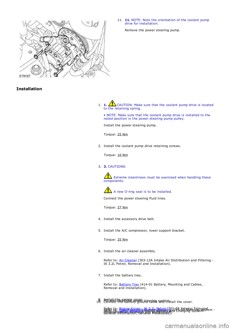
11.
NOTE: Note t he orientat ion of t he cool ant pump
dri ve for i nst all at ion.
Remove t he power s t eering pump.
11.
Installation 1. CAUTION: Make s ure that the coolant pump drive i s located
t o t he ret aining s pri ng.
• NOTE: Make s ure that t he coolant pump drive i s ins t al led t o t he
noted pos it ion in t he power st eeri ng pump pulley.
Inst all t he power s t eering pump.
T orque: 25 Nm 1.
Inst all t he cool ant pump drive retai ni ng s crews .
T orque: 10 Nm 2.
3. CAUTIONS: Ext reme cl eanli ness must be exerci sed when handli ng t hes e
component s. A new O-ri ng s eal i s to be ins tal led.
Connect t he power s t eering flui d li nes.
T orque: 27 Nm 3.
Inst all t he acces sory dri ve bel t.
4.
Inst all t he A/C compress or, l ower support bracket.
T orque: 25 Nm 5.
Inst all t he air cleaner as s embly.
Refer t o: Air Cleaner (303-12A Intake Ai r Dis tribut ion and Fil tering -
I6 3.2L Pet rol, Removal and Ins t al lat ion).
6.
Inst all t he bat t ery t ray.
Refer t o: Bat t ery Tray (414-01 Bat tery, Mount ing and Cables ,
Removal and Ins tall ati on).
7.
Inst all t he engi ne cover.
Refer t o: Engi ne Cover - I6 3.2L Pet rol (501-05 Int eri or Trim and
Ornament ati on, Removal and Ins tal lat ion).
8.
Fil l and bl eed the power s t eering s ys tem.
Refer t o: Power St eering Sys tem Bleeding (211-00 St eering Sys tem -
General Informat ion, General Procedures ).
9.
Connect t he batt ery ground cable and ins tall t he cover.
Refer t o: Specificati ons (414-00 Bat tery and Charging Sys tem -
10.
Page 583 of 3229
The SRS el ect ri cal connectors are uni que. DO NOT force, orat tempt t o connect electrical connect ors t o t he wrong socket s .
Driver air bag module ins tall ati on can be confirmed by heari ng2 audibl e clicks , 1 for each s pring. The module edges s houl d als o beflus h wit h t he s teering wheel.
Inst all t he dri ver air bag modul e.
If ins tal led, connect t he SRS ride-down el ect ri cal connectorconcealed at t he rear of t he s teeri ng col umn.6.
Secure t he wiring harnes s t o t he s teeri ng column.7.
Connect t he s teeri ng col umn el ect ri cal connectors.8.
Inst all t he s teeri ng col umn upper cowl .9.
Inst all t he s teeri ng col umn l ower cowl.10.
Inst all t he dri ver l ower ai r bag modul e.
Refer t o: Dri ver Lower Air Bag Module (501-20B SupplementalRes traint Sys t em, Removal and Inst all at ion).
11.
Connect t he batt ery ground cable.
Refer t o: Specificati ons (414-00 Bat tery and Charging Sys tem -General Informat ion, Specificati ons).
12.
If a new s t eering column has been i nst all ed, confi gure t he s teeri ngcolumn l ock us i ng Land Rover approved di agnos t ic equipment.13.
Page 596 of 3229
Publi s hed: 11-May-2011
Steering Column Switches - Steering Column Lock Module
Removal and Inst all ati on
Removal
• NOTE: On vehicles bui lt from VIN 091770 t he s teeri ng col umn l ock modul e may be a non-functi onal component .
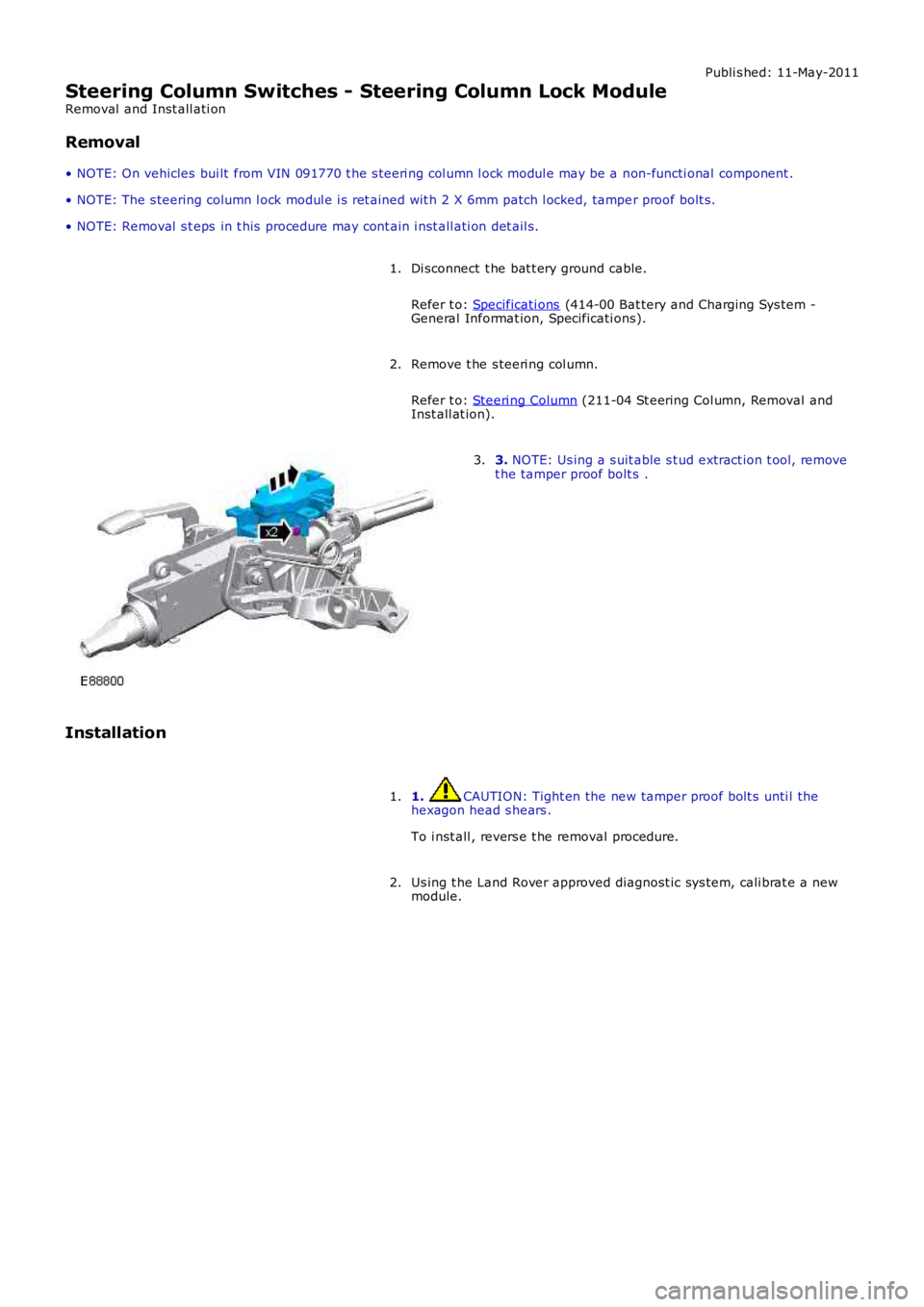
• NOTE: The s teering column l ock modul e i s ret ained wit h 2 X 6mm patch l ocked, tamper proof bolt s.
• NOTE: Removal s t eps in t his procedure may cont ain i nst all ati on det ail s.
Di sconnect t he bat t ery ground cable.
Refer t o: Specificati ons (414-00 Bat tery and Charging Sys tem -General Informat ion, Specificati ons).
1.
Remove t he s teeri ng col umn.
Refer t o: Steeri ng Column (211-04 St eering Col umn, Removal andInst all at ion).
2.
3. NOTE: Us ing a s uit able s t ud extract ion t ool, removet he tamper proof bolt s .3.
Installation
1. CAUTION: Tight en the new tamper proof bolt s unti l thehexagon head s hears .
To i nst all , revers e t he removal procedure.
1.
Us ing t he Land Rover approved diagnost ic sys tem, cali brat e a newmodule.2.
Page 652 of 3229
Publi s hed: 11-May-2011
Engine - I6 3.2L Petrol - Valve Clearance Adjustment
General Procedures
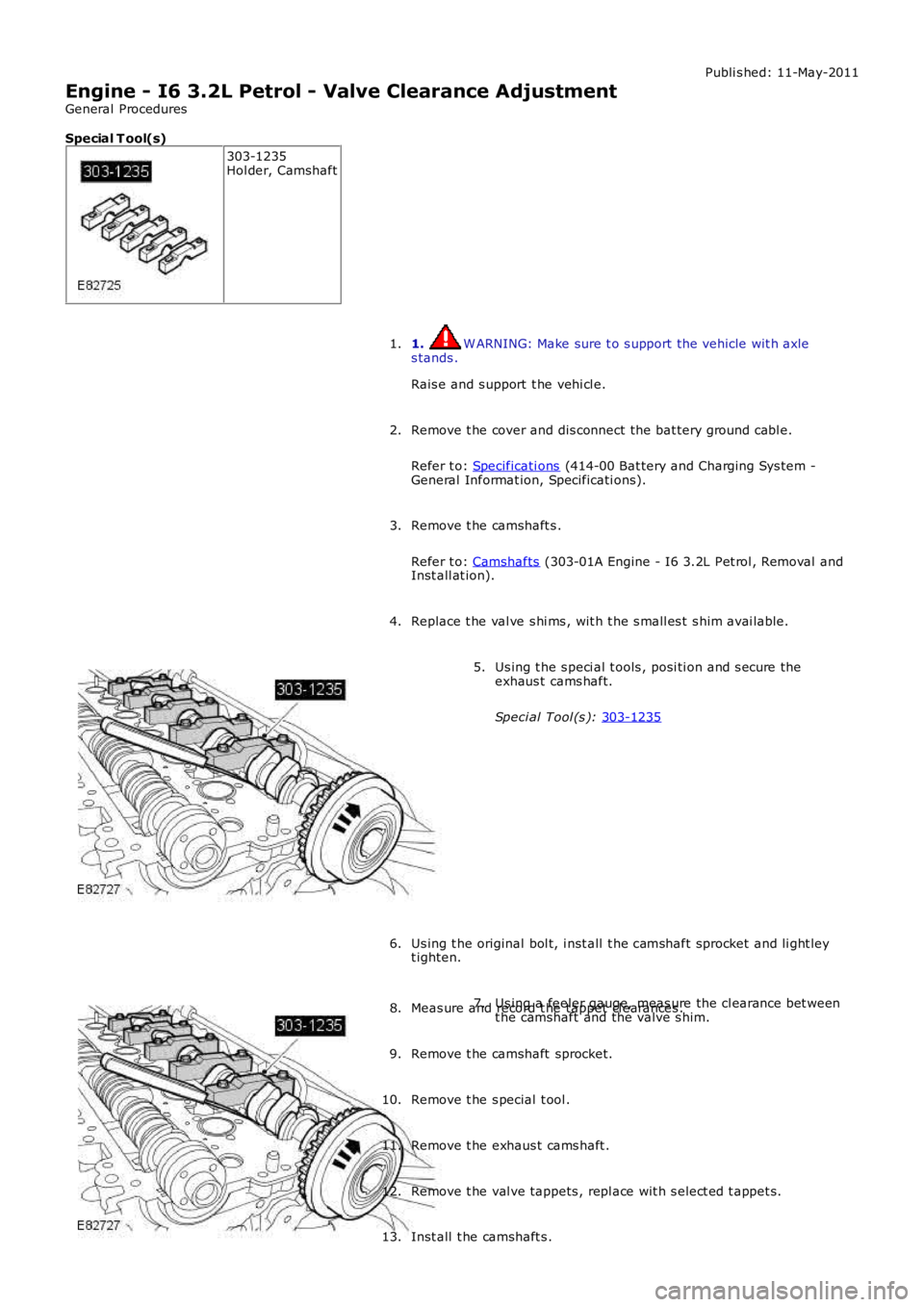
Special T ool(s) 303-1235
Hol der, Camshaft
1. W ARNING: Make sure t o s upport the vehicle wit h axle
s tands .
Rais e and s upport t he vehi cl e.
1.
Remove t he cover and dis connect the bat tery ground cabl e.
Refer t o: Specificati ons (414-00 Bat tery and Charging Sys tem -
General Informat ion, Specificati ons).
2.
Remove t he camshaft s .
Refer t o: Camshafts (303-01A Engine - I6 3.2L Pet rol , Removal and
Inst all at ion).
3.
Replace t he val ve s hi ms , wit h t he s mall es t s him avai lable.
4. Us ing t he s peci al t ools , posi ti on and s ecure the
exhaus t cams haft.
Speci al Tool (s ): 303-1235 5.
Us ing t he original bol t, i nst all t he camshaft sprocket and li ght ley
t ighten.
6. Us ing a feeler gauge, meas ure the cl earance bet ween
t he camshaft and the valve s him.
7.
Meas ure and record t he tappet cl earances .
8.
Remove t he camshaft sprocket.
9.
Remove t he s pecial t ool .
10.
Remove t he exhaus t cams haft .
11.
Remove t he val ve tappets , repl ace wit h s elect ed t appet s.
12.
Inst all t he camshaft s .
13.
Page 653 of 3229
Refer t o: Camshafts (303-01A Engine - I6 3.2L Pet rol , Removal andInst all at ion).
Connect t he batt ery ground cable and ins tall t he cover.
Refer t o: Specificati ons (414-00 Bat tery and Charging Sys tem -General Informat ion, Specificati ons).
14.