Page 734 of 3229
Publi s hed: 11-May-2011
Engine - I6 3.2L Petrol - Rear End Accessory Drive (READ) Idler Shaft
Assembly
Removal and Inst all ati on
Special T ool(s) 303-1486
Mandrel 303-1488
Rear End Acces sory Drive (READ) Idler Shaft As s embl y Extract or
Removal
• NOTE: Removal s t eps in t his procedure may cont ain i nst all ati on det ail s.
Refer t o: Specificati ons (414-00 Bat tery and Charging Sys tem -
General Informat ion, Specificati ons).
1.
2. W ARNING: Do not work on or under a vehi cle s upported onl y
by a jack. Al ways support t he vehi cl e on s afet y s tands .
Rais e and s upport t he vehi cl e.
2.
Refer t o: Rear End Acces s ory Drive (READ) (303-05A Access ory Dri ve
- I6 3.2L Pet rol , Removal and Ins t al lat ion).
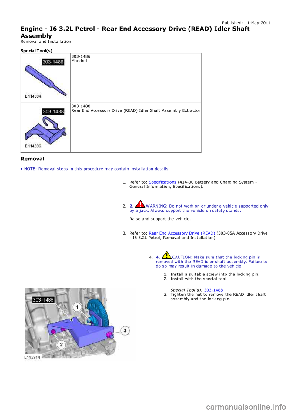
3. 4. CAUTION: Make s ure that the locki ng pin i s
removed wit h the READ idler s haft as s embly. Fai lure to
do s o may res ult i n damage to the vehicle.
Inst all a s uit able s crew int o the locki ng pin.
1.
Inst all wi th t he s peci al t ool.
Speci al Tool (s ): 303-1488 2.
Tight en the nut t o remove the READ idler s haft
as sembl y and t he locki ng pin.
3.
4.
Page 736 of 3229
- I6 3.2L Pet rol , Removal and Ins t al lat ion).
Lower the vehicle.5.
Refer t o: Specificati ons (414-00 Bat tery and Charging Sys tem -General Informat ion, Specificati ons).6.
Page 737 of 3229
Publi s hed: 11-May-2011
Engine - I6 3.2L Petrol - Engine
Removal
Special T ool(s)
205-857Remover, Halfs haft
General Equipment
Powert rai n Jack
• NOTE: In t hi s procedure t he engi ne and t rans mis s ion are removed t oget her.
1. W ARNING: Make sure t o s upport the vehicle wit h axles tands .
Rais e and s upport t he vehi cl e.
1.
Remove t he cover and dis connect the bat tery ground cabl e.
Refer t o: Specificati ons (414-00 Bat tery and Charging Sys tem -General Informat ion, Specificati ons).
2.
Remove t he engi ne cover.
Refer t o: Engi ne Cover - I6 3.2L Pet rol (501-05 Int eri or Trim andOrnament ati on, Removal and Ins tal lat ion).
3.
Remove t he plenum box acces s panel.
Refer t o: Plenum Chamber (412-01 Cl imat e Control, Removal andInst all at ion).
4.
Remove t he bat t ery t ray.
Refer t o: Bat t ery Tray (414-01 Bat tery, Mount ing and Cables ,Removal and Ins tall ati on).
5.
Remove t he air cleaner as s embly.
Refer t o: Air Cleaner (303-12A Intake Ai r Dis tribut ion and Fil tering -I6 3.2L Pet rol, Removal and Ins t al lat ion).
6.
Drai n t he cool ant .
Refer t o: Cool ing Sys tem Drai ni ng, Fi lli ng and Bleeding (303-03AEngine Cooli ng - I6 3.2L Petrol, General Procedures).
7.
Remove t he s tart er mot or.
Refer t o: Start er Motor (303-06A Starti ng Sys t em - I6 3.2L Pet rol ,Removal and Ins tall ati on).
8.
Remove t he cat alyti c convert ers .
Refer t o: Cat alyt ic Converter (309-00A Exhaus t Syst em - I6 3.2LPetrol, Removal and Ins tall ati on).
9.Remove t he lower engi ne s tabil izer bar.
Refer t o: Engi ne Lower Support Ins ulat or (303-01A Engine - I6 3.2LPetrol, Removal and Ins tall ati on).
10.Remove t he front subframe as s embly.
Refer t o: Front Subframe (502-00 Uni -Body, Subframe and Mount ing
11.
Page 751 of 3229
Remove t he engi ne cover.
Refer t o: Engi ne Cover - I6 3.2L Pet rol (501-05 Int eri or Trim andOrnament ati on, Removal and Ins tal lat ion).
38.
Connect t he batt ery ground cable and ins tall t he cover.
Refer t o: Specificati ons (414-00 Bat tery and Charging Sys tem -General Informat ion, Specificati ons).
39.
Refi ll and bleed t he power st eeri ng.
Refer t o: Power St eering Sys tem Bleeding (211-00 St eering Sys tem -General Informat ion, General Procedures ).
40.
Carry out the fi nal halfshaft and sus pensi on ti ghtening wi th thevehicle on it s wheel s .41.
Page 792 of 3229
ItemPart NumberDescription
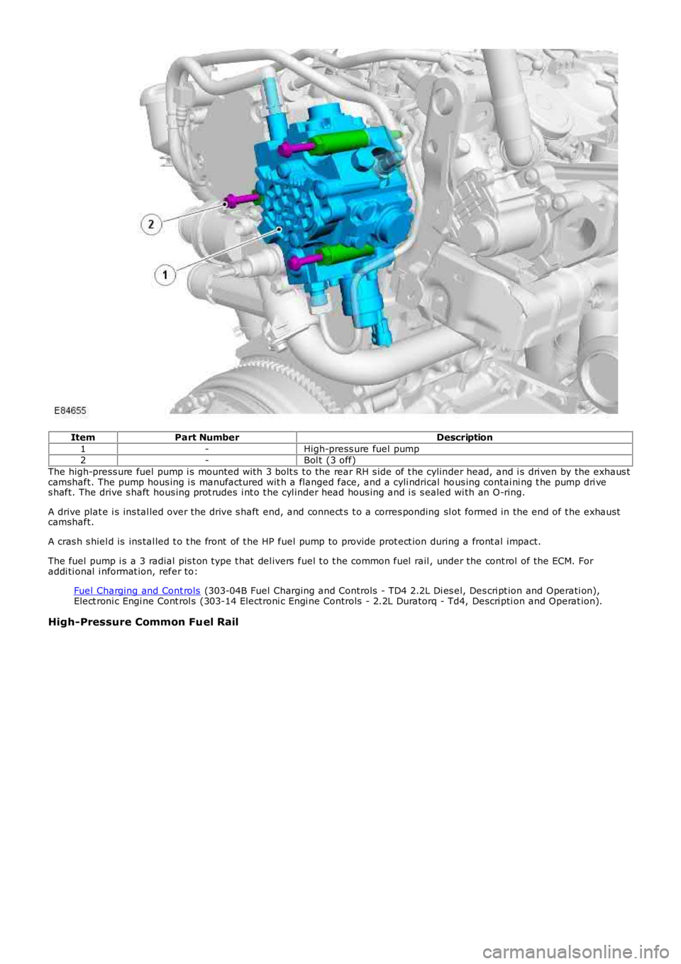
1-High-press ure fuel pump2-Bol t (3 off)
The high-press ure fuel pump i s mounted wi th 3 bolt s t o the rear RH s ide of t he cylinder head, and i s dri ven by the exhaus tcamshaft. The pump hous ing i s manufactured wit h a flanged face, and a cyli ndrical hous ing contai ni ng t he pump dri ves haft. The drive s haft hous ing prot rudes i nt o t he cyl inder head hous ing and i s s ealed wi th an O-ring.
A drive plat e i s ins tal led over the drive s haft end, and connect s t o a corres ponding sl ot formed in the end of t he exhaus tcamshaft.
A cras h s hiel d is ins tal led t o t he front of t he HP fuel pump to provide prot ect ion during a front al impact.
The fuel pump i s a 3 radial pis t on type t hat del ivers fuel t o t he common fuel rail , under the cont rol of the ECM. Foraddi ti onal i nformat ion, refer to:
Fuel Charging and Cont rols (303-04B Fuel Charging and Controls - TD4 2.2L Di es el, Des cri pt ion and Operati on),Elect roni c Engi ne Cont rol s (303-14 Electroni c Engi ne Controls - 2.2L Duratorq - Td4, Descri pti on and Operat ion).
High-Pressure Common Fuel Rail
Page 793 of 3229
ItemPart NumberDescription
1-High-pres sure common fuel rail2-Bolt (2 off)
The common fuel rail is manufact ured from forged s teel and is s ecured wi th 2 bolt s to the cyli nder head, above t he li ne oft he exhaus t cams haft . The fuel rai l st ores press uri zed fuel from t he high-pres sure fuel pump and deli vers t he fuel t o thefuel inject ors .
The fuel rai l pres sure is regulat ed by a Pres s ure Cont rol Valve (PCV) l ocat ed at the fuel pump end of the fuel rail , undert he cont rol of the ECM. A fuel pres sure s ensor i ns t alled in t he oppos i te end of t he fuel rai l provides t he act ual fuelpres s ure s ignal to the ECM. For addi ti onal i nformat ion, refer to:
Fuel Charging and Cont rols (303-04B Fuel Charging and Controls - TD4 2.2L Di es el, Des cri pt ion and Operati on),Elect roni c Engi ne Cont rol s (303-14 Electroni c Engi ne Controls - 2.2L Duratorq - Td4, Descri pti on and Operat ion).
Fuel Injectors
Page 794 of 3229
ItemPart NumberDescription
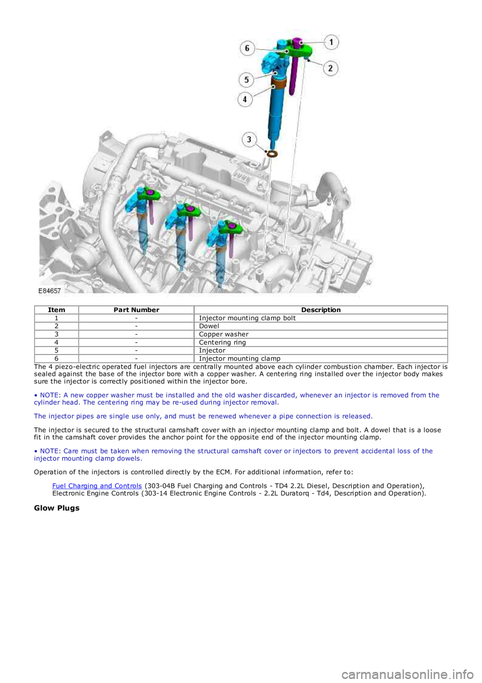
1-Injector mount ing clamp bol t2-Dowel
3-Copper washer
4-Cent ering ring5-Injector
6-Injector mount ing clamp
The 4 pi ezo-el ect ri c operated fuel injectors are cent rall y mounted above each cyl inder combus ti on chamber. Each i njector iss eal ed agai nst the bas e of the injector bore wit h a copper was her. A cent ering ri ng ins tal led over the i njector body makess ure t he i nject or is correct ly pos i ti oned wi thi n t he inject or bore.
• NOTE: A new copper washer mus t be i ns t alled and the ol d was her dis carded, whenever an inject or is removed from t hecyl inder head. The cent eri ng ri ng may be re-us ed duri ng inject or removal.
The inject or pi pes are s i ngl e us e only, and mus t be renewed whenever a pi pe connection is releas ed.
The inject or is s ecured t o t he st ruct ural cams haft cover wit h an i nject or mounti ng cl amp and bolt . A dowel that i s a l oos efi t in the cams haft cover provi des the anchor point for the opposi te end of the i njector mounti ng clamp.
• NOTE: Care must be taken when removi ng the st ruct ural cams haft cover or i njectors to prevent acci dent al los s of theinject or mount ing cl amp dowels .
Operat ion of t he inject ors i s cont rol led direct ly by the ECM. For addi ti onal i nformat ion, refer to:
Fuel Charging and Cont rols (303-04B Fuel Charging and Controls - TD4 2.2L Di es el, Des cri pt ion and Operati on),Elect roni c Engi ne Cont rol s (303-14 Electroni c Engi ne Controls - 2.2L Duratorq - Td4, Descri pti on and Operat ion).
Glow Plugs
Page 798 of 3229
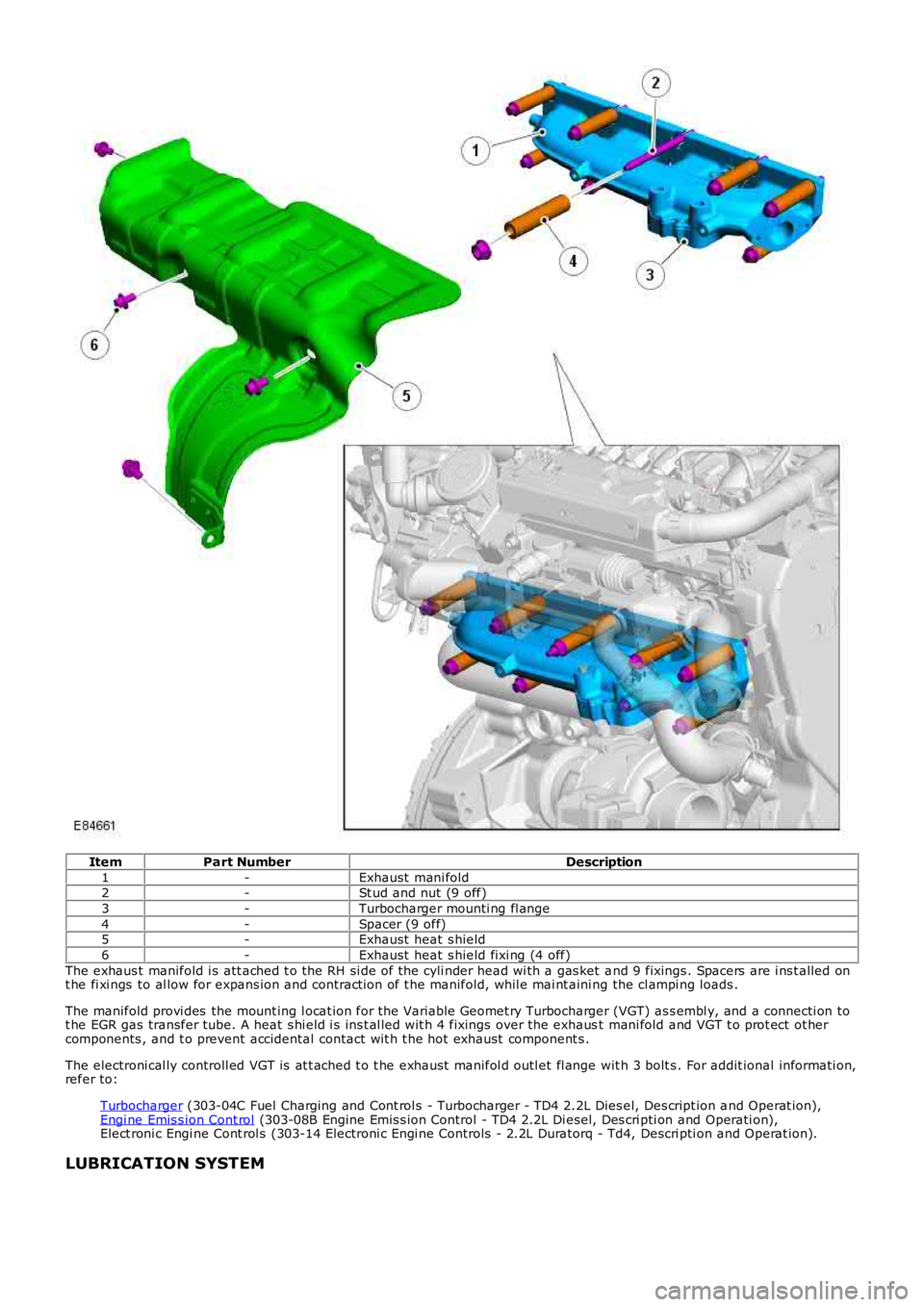
ItemPart NumberDescription
1-Exhaust mani fold2-St ud and nut (9 off)
3-Turbocharger mounti ng fl ange
4-Spacer (9 off)5-Exhaust heat s hield
6-Exhaust heat s hield fixi ng (4 off)
The exhaus t manifold i s att ached t o t he RH si de of the cyli nder head wi th a gas ket and 9 fixings . Spacers are i ns t alled ont he fi xi ngs to al low for expans ion and contract ion of t he manifold, whil e mai nt aini ng the cl ampi ng loads .
The manifold provi des the mount ing l ocat ion for the Variable Geomet ry Turbocharger (VGT) as s embl y, and a connecti on tot he EGR gas transfer tube. A heat s hi eld i s ins t al led wit h 4 fixings over the exhaust mani fold and VGT t o prot ect ot hercomponents , and t o prevent accidental contact wit h t he hot exhaust component s .
The electroni cal ly controll ed VGT is at t ached t o t he exhaus t manifol d outl et fl ange wit h 3 bolt s . For addit ional informati on,refer to:
Turbocharger (303-04C Fuel Charging and Cont rol s - Turbocharger - TD4 2.2L Dies el, Des cript ion and Operat ion),Engi ne Emis s ion Cont rol (303-08B Engine Emis s ion Control - TD4 2.2L Di esel , Des cri pti on and Operati on),Elect roni c Engi ne Cont rol s (303-14 Electroni c Engi ne Controls - 2.2L Duratorq - Td4, Descri pti on and Operat ion).
LUBRICATION SYSTEM