Page 493 of 3229
Refer t o: Specificati ons (414-00 Bat tery and Charging Sys tem -General Informat ion, Specificati ons).
Bleed t he brake s ys tem.
Refer t o: Brake Syst em Bl eedi ng (206-00 Brake Syst em - GeneralInformat ion, General Procedures).
12.
Vehicles with manual transmission
Bleed t he clut ch sys t em.
Refer t o: Clutch Sys tem Bleeding (308-00 ManualTrans mi ss ion/Transaxle and Clut ch - General Informati on, GeneralProcedures ).
13.
Page 494 of 3229
Publi s hed: 11-May-2011
Power Brake Actuation - Brake Vacuum PumpI6 3.2L Petrol
Removal and Inst all ati on
Removal
• NOTE: Removal s t eps in t his procedure may cont ain i nst all ati on det ail s.
Remove t he cover and dis connect the bat tery ground cabl e.
Refer t o: Specificati ons (414-00 Bat tery and Charging Sys tem -
General Informat ion, Specificati ons).
1.
Remove t he engi ne cover.
Refer t o: Engi ne Cover - I6 3.2L Pet rol (501-05 Int eri or Trim and
Ornament ati on, Removal and Ins tal lat ion).
2.
Remove t he bat t ery t ray.
Refer t o: Bat t ery Tray (414-01 Bat tery, Mount ing and Cables ,
Removal and Ins tall ati on).
3.
Remove t he air cleaner as s embly.
Refer t o: Air Cleaner (303-12B Intake Ai r Dis tribut ion and Fil tering -
TD4 2.2L Dies el, Removal and Inst all ati on).
4. Remove t he A/C compress or, upper s upport bracket.
T orque: M10 45 Nm M8
25 Nm M6
10 Nm 5.
Di sconnect t he brake boost er vacuum l ine from t he brake vacuum
pump.
6.
Page 496 of 3229
Publi s hed: 11-May-2011
Power Brake Actuation - Brake Vacuum PumpTD4 2.2L Diesel
Removal and Inst all ati on
Removal
• NOTE: Removal s t eps in t his procedure may cont ain i nst all ati on det ail s.
Remove t he cover and dis connect the bat tery ground cabl e.
Refer t o: Specificati ons (414-00 Bat tery and Charging Sys tem -
General Informat ion, Specificati ons).
1.
Remove t he engi ne cover.
Refer t o: Engi ne Cover - TD4 2.2L Dies el (501-05 Interior Tri m and
Ornament ati on, Removal and Ins tal lat ion).
2.
Remove t he air cleaner as s embly.
Refer t o: Air Cleaner (303-12B Intake Ai r Dis tribut ion and Fil tering -
TD4 2.2L Dies el, Removal and Inst all ati on).
3. T orque:
9 Nm 4.
5.
Page 502 of 3229

Publi s hed: 11-May-2011
Anti-Lock Control - Anti-Lock Brake System (ABS) Module
Removal and Inst all ati on
Removal
• CAUTIO NS:
Extreme cleanli nes s mus t be exercis ed when handli ng thes e component s.
If brake fluid is s pil t on the pai ntwork, t he affect ed area must be immedi ately washed down wi th col d wat er.
All vehicles
1. W ARNING: Make sure t o s upport the vehicle wit h axles tands .
Rais e and s upport t he vehi cl e.
1.
Di sconnect t he bat t ery ground cable.
Refer t o: Specificati ons (414-00 Bat tery and Charging Sys tem -General Informat ion, Specificati ons).
2.
Remove t he bat t ery t ray.
Refer t o: Bat t ery Tray (414-01 Bat tery, Mount ing and Cables ,Removal and Ins tall ati on).
3.
Right-hand drive vehicles
Remove t he plenum chamber panel.4.
Left-hand drive vehicles
Remove t he winds hield wiper motor and l inkage.
Refer t o: W i nds hield W i per Mot or (501-16 W ipers and W as hers ,Removal and Ins tall ati on).
5.
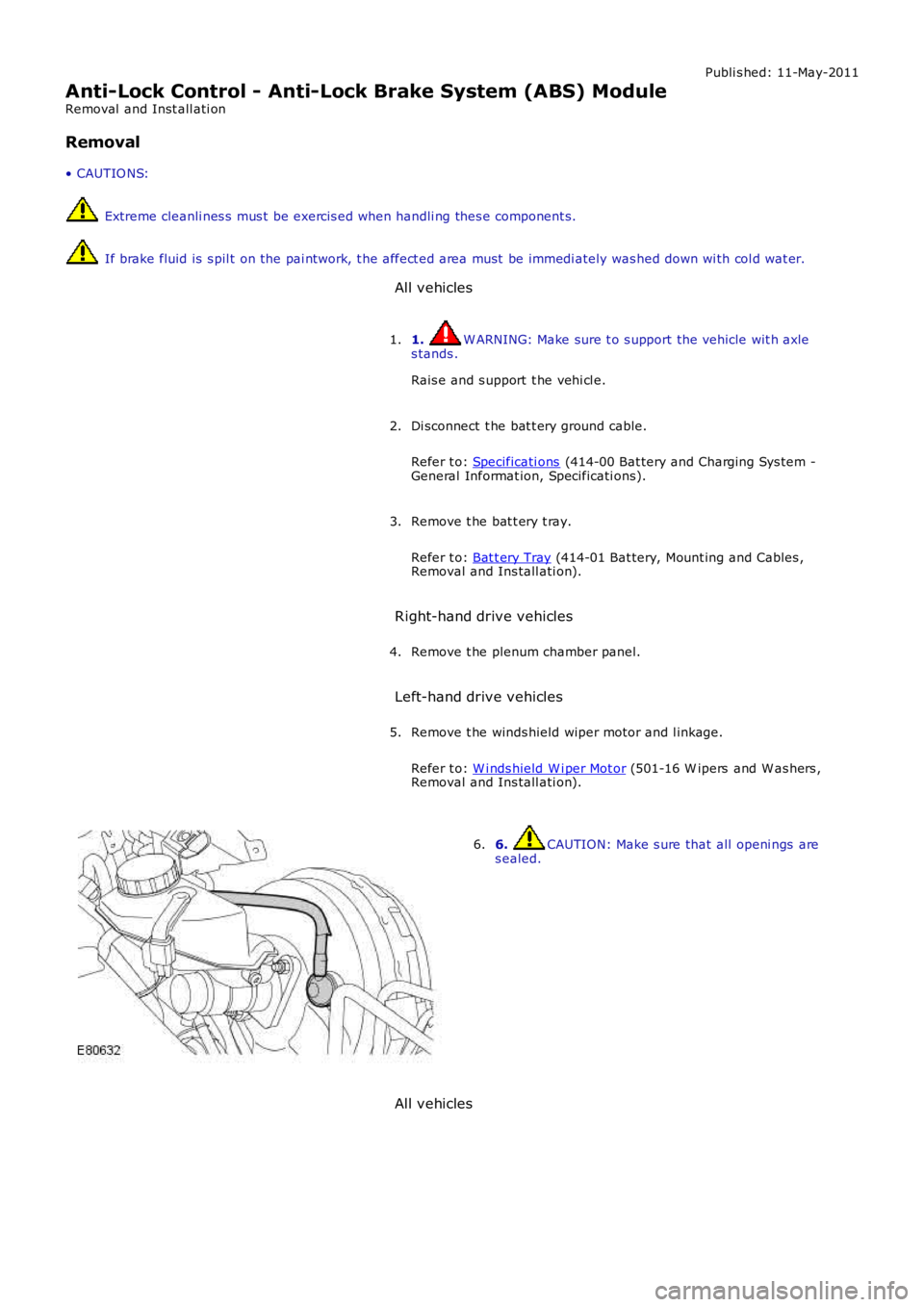
6. CAUTION: Make s ure that all openi ngs ares ealed.6.
All vehicles
Page 505 of 3229
Inst all t he winds hield wiper motor and l inkage.
Refer t o: W i nds hield W i per Mot or (501-16 W ipers and W as hers ,Removal and Ins tall ati on).
7.
Right-hand drive vehicles
Inst all t he plenum chamber panel.8.
All vehicles
Inst all t he bat t ery t ray.
Refer t o: Bat t ery Tray (414-01 Bat tery, Mount ing and Cables ,Removal and Ins tall ati on).
9.
Connect t he batt ery ground cable.
Refer t o: Specificati ons (414-00 Bat tery and Charging Sys tem -General Informat ion, Specificati ons).
10.
Bleed t he brake s ys tem.
Refer t o: Brake Syst em Bl eedi ng (206-00 Brake Syst em - GeneralInformat ion, General Procedures).
11.
If a new component has been ins t al led, configure usi ng Land Roverapproved diagnos t ic equipment .12.
Page 526 of 3229
Publi s hed: 11-May-2011
Anti-Lock Control - Stability Assist - Accelerometer
Removal and Inst all ati on
Removal
Di sconnect t he bat t ery ground cable.
Refer t o: Specificati ons (414-00 Bat tery and Charging Sys tem -
General Informat ion, Specificati ons).
1.
Remove t he fl oor consol e.
Refer t o: Fl oor Cons ole (501-12 Inst rument Panel and Cons ole,
Removal and Ins tall ati on).
2. T orque:
6 Nm 3.
Installation To i nst all , revers e t he removal procedure.
1.
If a new component has been ins t al led, configure usi ng Land Rover
approved diagnos t ic equipment .
2.
Page 545 of 3229
Publi s hed: 11-May-2011
Power Steering - Power Steering Pressure TestTD4 2.2L Diesel
General Procedures
Special T ool(s)
211-011-01Valve Bl ock, Power Steeri ng Pres s ure Tes t
211-011-02Hos e, Power St eering Press ure Tes t
211-011-12Adapter, Power St eering Press ure Tes t
211-287Hos e and Gauge, Power St eering Pres s ure Tes t
Di sconnect t he bat t ery ground cable.
Refer t o: Specificati ons (414-00 Bat tery and Charging Sys tem -General Informat ion, Specificati ons).
1.
Remove t he engi ne cover.
Refer t o: Engi ne Cover - TD4 2.2L Dies el (501-05 Interior Tri m andOrnament ati on, Removal and Ins tal lat ion).
2.
3. W ARNING: Make sure t o s upport the vehicle wit h axles tands .
Rais e and s upport t he vehi cl e.
3.
Page 548 of 3229

10 s econds .
W it h the engi ne at idle, s lowl y turn t he s teeri ng wheel and
hold on full l ock. Record t he pres s ure readi ng.
Repeat t he above procedure for t he other s ide. Record t he pres s ure readi ng.16.
W it h the engi ne at idle, rel ease the s t eering wheel. The press ure
s houl d be, at or bel ow, the pres s ure specified.
17.
Pres s ure out si de t hi s t olerance, i ndicat es a fault .
18.
19. CAUTION: Pump damage wi ll occur if t he t est valve is
clos ed for l onger peri ods .
To det ermi ne if t he fault is i n t he st eeri ng pump or the st eeri ng
rack, clos e the tes t val ve for a maxi mum of 5 s econds.
19.
If the press ures recorded fal l out s ide t he given values, replace the
power st eeri ng pump.
20.
If the maxi mum pump pres sure i s correct, t hen s uspect the power
s teering rack.
21.
22. CAUTION: Dis card flui d s iphoned from t he power st eeri ng
s yst em.
On compl et ion of t he t est s t op the engi ne, dis connect t he bat t ery
ground cable and s i phon t he fluid from t he power st eering res ervoir.
22.
Di sas s emble t he t es t equipment .
23.
Clean t he component mat ing faces . Inst all a new O-ring s eal.
Connect t he high-press ure li ne to the power s teeri ng pump.
T orque:
22 Nm 24.
Secure t he power s t eering hi gh pres s ure pi pe support bracket.
25.
Secure t he fuel li nes to the power s teeri ng high press ure pipe wi th
new cable t ies .
26.
Inst all t he turbocharger int ake tube.
27.
Inst all t he engi ne cover.
Refer t o: Engi ne Cover - TD4 2.2L Dies el (501-05 Interior Tri m and
Ornament ati on, Removal and Ins tal lat ion).
28.
Connect t he batt ery ground cable.
Refer t o: Specificati ons (414-00 Bat tery and Charging Sys tem -
General Informat ion, Specificati ons).
29.
30. CAUTION: Only us e new fl uid from a s ealed container.
Refi ll and bleed t he power st eeri ng.
30.