2006 LAND ROVER FRELANDER 2 torque
[x] Cancel search: torquePage 8 of 3229
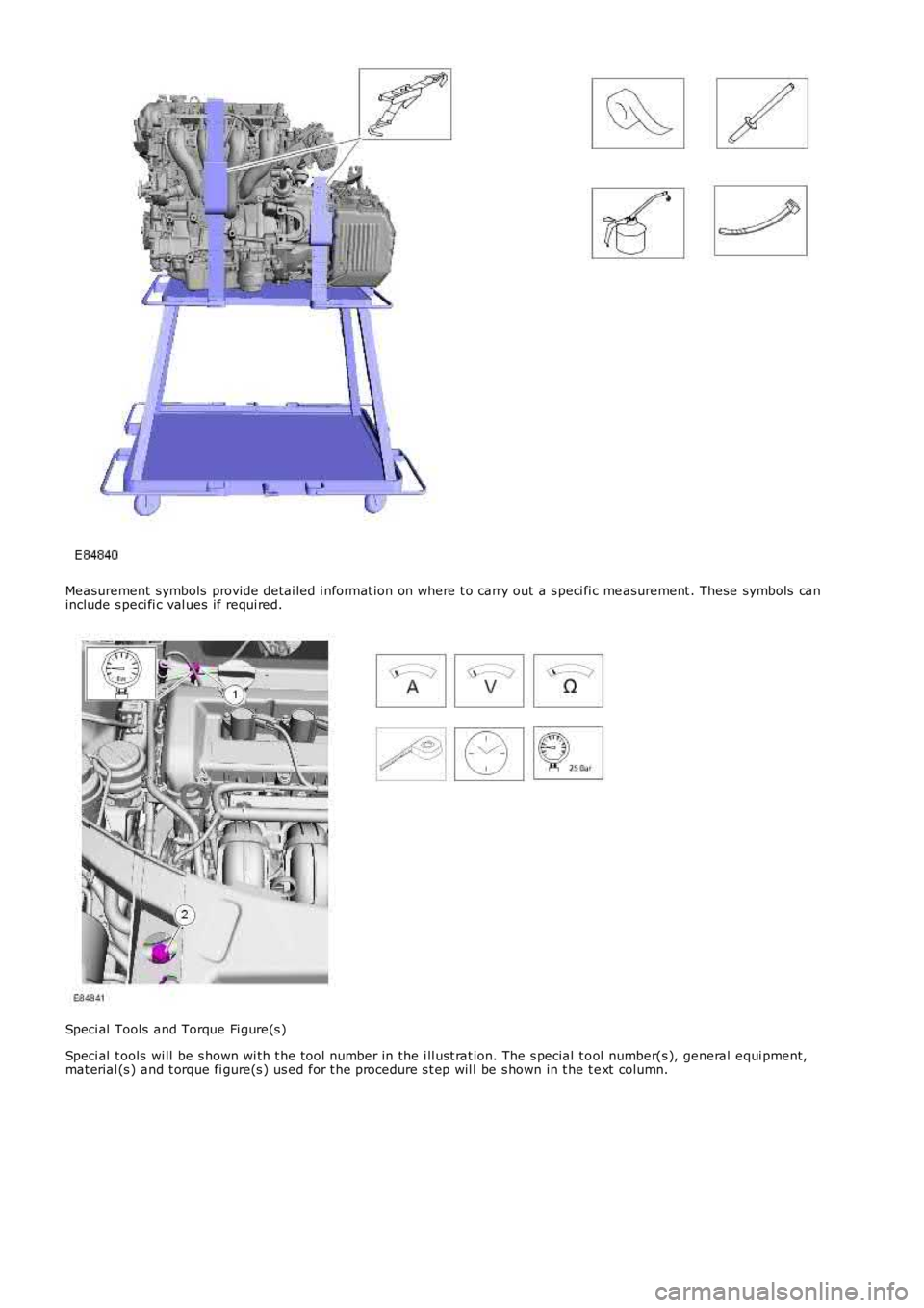
Measurement symbols provide detai led i nformat ion on where t o carry out a s peci fi c measurement . These symbols caninclude s peci fi c val ues if requi red.
Speci al Tools and Torque Fi gure(s )
Speci al t ools wi ll be s hown wi th t he t ool number in the i ll ust rat ion. The s pecial t ool number(s ), general equi pment,mat erial (s ) and t orque fi gure(s ) us ed for t he procedure s t ep wil l be s hown in t he t ext column.
Page 13 of 3229
Land Rover part s are manufact ured to t he s ame exact ing st andards as t he origi nal fact ory fit t ed components . For thisreas on, it is ess enti al t hat onl y genui ne Land Rover part s are used during mai ntenance or repai r.
Att enti on is parti cul arly drawn t o t he fol lowing poi nt s concerni ng repairs and t he fi tt ing of replacement parts andacces sories .
Safet y feat ures and corros ion prevent ion t reat ments embodied in t he vehicle may be impai red i f other than Land Roverrecommended part s are fi tt ed. In cert ain t errit ori es , l egi sl ati on prohibi ts t he fit ti ng of parts not t o manufact urer'ss pecificati on. Torque wrench s ett ing figures , where gi ven, mus t be adhered t o and l ocking devices , where s peci fi ed mus tbe us ed. If t he efficiency of a locki ng devi ce is impaired duri ng removal it mus t be repl aced.
Owners purchas ing acces s ori es whils t t ravell ing abroad mus t ens ure t hat the acces s ory and it s fi tt ed locati on on t hevehi cl e conform t o legal requirements .
The t erms of t he vehi cl e warranty may be i nvali dat ed by t he fit ti ng of parts ot her than t hos e recommended by Land Rover.
• NOTE: The fit ti ng of non-approved Land Rover parts and acces s ori es or the carrying out of non-approved al terati ons orconvers i ons may be dangerous . Any of the foregoing could affect t he s afety of t he vehicle and occupants ; al so, t he termsand condi ti ons of t he vehi cle warranty may als o be inval idated .
All Land Rover recommended part s have t he ful l backing of t he vehi cl e warranty.
Land Rover Dealers are obli ged to s upply onl y Land Rover recommended part s .
Specifications
Land Rover are cons tant ly s eeki ng t o improve the specificati on, des ign and producti on of their vehicles and al terat ionst ake pl ace accordingly. W hi ls t every effort i s made t o ens ure t he accuracy of t his Manual, i t should not be regarded as aninfalli ble guide to current s pecificati ons of any parti cular vehicle.
This Manual does not cons t it ute an offer for sal e of any part icul ar vehi cl e. Land Rover dealers are not agents of Land Roverand have no authori ty to bi nd the manufact urer by any expres sed or i mpli ed undertaking or repres ent ati on.
Page 16 of 3229
Woodruff keys
W oodruff keys may be reus ed provided t here i s no i ndi cat ion of wear or dis torti on.
Remove any burrs from edges of keyways us ing a fine fil e.
Split pins
Never at tempt t o s t raight en and reus e a s pli t pin, always make s ure that repl acement pins are of the correct si ze for t hehole i n which t hey are to be ins tal led.
Screw Threads
Damaged nuts , bolt s and s crews mus t always be dis carded. Att empti ng to recut or repai r damaged threads wi th at ap or di e i mpai rs the s t rength and fi t of t he t hreads and is not recommended.
• NOTE: Duri ng cert ai n repai r operat ions , it may be neces sary t o remove t races of t hread locking agent s us ing a tap.W here thi s is neces sary, t he i ns t ructi on to do s o wi ll appear in the relevant operation and it i s ess enti al that a t ap of thecorrect s ize and t hread i s used.
Some bolt s are coat ed wit h a thread locki ng agent and unles s s tat ed otherwis e, they mus t not be reus ed. Newbolt s havi ng the same part number as the original mus t always be i nst all ed. W hen nuts or bolt s are to bedis carded, t he repai r operat ion and relevant torque chart will i ncl ude an ins truct ion to that effect . Do not usepropri etary thread locki ng agent s as t hey may not meet the specificati on required. See al so Encapsul at ed('Patched') Bol ts and Screws.Always make s ure that repl acement nuts and bol ts are at leas t equal i n s trengt h t o thos e t hat they are repl acing.Cast ell ated nut s mus t not be loosened t o accept a s pli t pin except in recommended cas es when thi s forms part ofan adjus tment .Do not all ow oil or greas e t o enter bli nd holes , the hydrauli c acti on res ult ing from ti ght ening t he bolt or s tud cans plit t he housi ng and als o gi ve a fal s e torque reading.Always t ighten a nut, bolt or s crew to t he s peci fi ed torque fi gure, damaged or corroded threads can give a fals et orque reading.Nut and bolt loos ening and t ightening sequences , where gi ven, mus t ALW AY S be foll owed. Di st ort ion ofcomponents or fault y s eal ing of joints wil l res ul t if t he s equences are not fol lowed. W here an ins t ructi on is gi ven tot ighten i n s tages , thes e s tages mus t be adhered t o; do not at t empt to combi ne st ages part icul arl y where cert ains tages involve t ight eni ng by degrees.To check or re-t ighten a fi xing t o a s peci fi ed t orque, firs t loosen a quart er of a turn, t hen ret ighten to the s peci fi edt orque fi gure.Unles s ins t ructed ot herwis e, do not lubricat e bolt or nut t hreads pri or t o i nst all ing.
W here it i s s tat ed t hat bolt s and s crews may be reus ed, t he fol lowi ng procedures must be carri ed out:
Check t hat threads are undamaged.Remove all t races of locki ng agent from the threads .
CAUTION: DO NOT us e a wi re brus h; take care t hat threads are not damaged.
Make s ure t hat threads are clean and free from oil or greas e.Apply t he s pecified locki ng agent t o t he bolt t hreads .
Bolt and Nut Identification
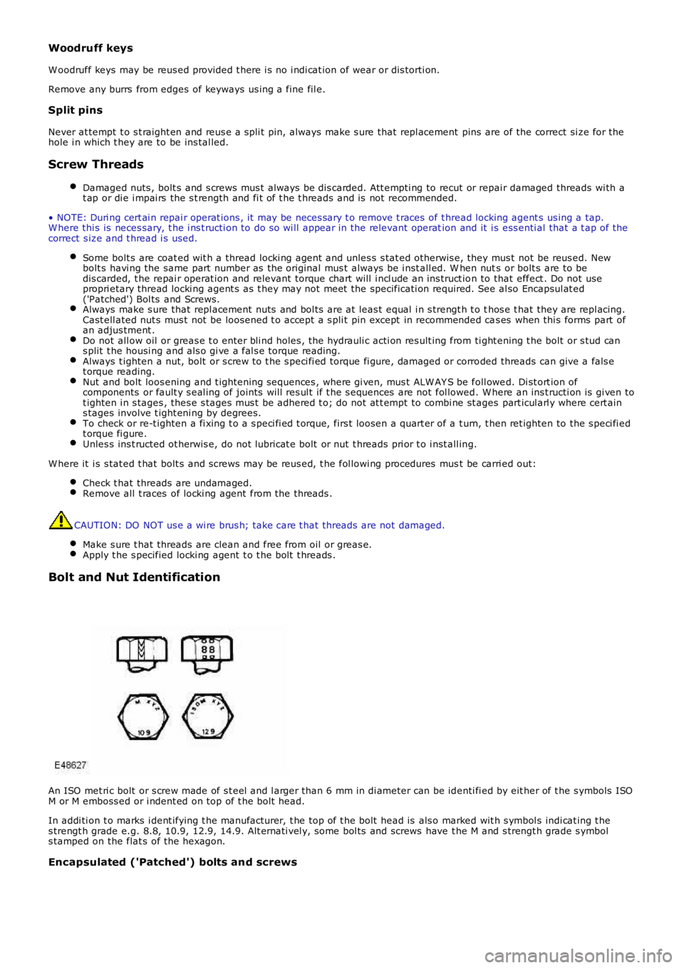
An ISO met ri c bolt or s crew made of s t eel and l arger than 6 mm in di ameter can be identi fi ed by eit her of t he s ymbols ISOM or M emboss ed or i ndent ed on top of t he bolt head.
In addi ti on t o marks i dent ifying t he manufacturer, t he top of t he bolt head is als o marked wit h s ymbol s indi cat ing t hes trengt h grade e.g. 8.8, 10.9, 12.9, 14.9. Alt ernati vel y, some bol ts and screws have t he M and s trengt h grade s ymbols tamped on the flat s of the hexagon.
Encapsulated ('Patched') bolts and screws
Page 20 of 3229
All fuel hos es are made up of two lami nat ions , an armoured rubber out er sl eeve and an inner vi ton core. W henever a hos eis removed, make sure t hat t he i nner bore is i ns pected t o check t hat the vi ton l ini ng has not become s eparated from t heouter s leeve.
W ARNING: Never att empt t o repair fuel hos es or recti fy leaki ng 'quick-fit ' connect ors the fuel hos e and connectorsmus t be repl aced as an as s embly.
Fuel s ys tem hos e cl ips
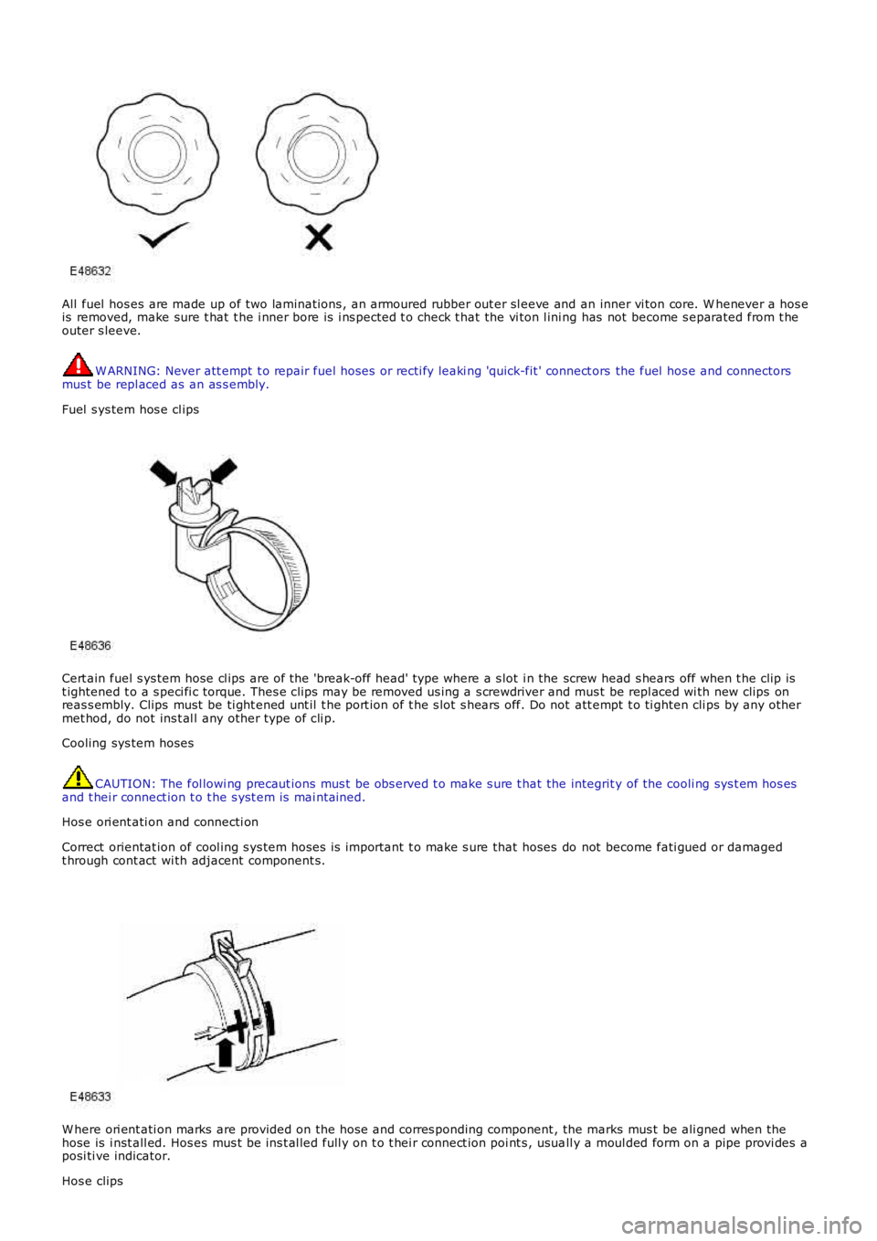
Cert ain fuel s ys tem hose cl ips are of the 'break-off head' type where a s lot i n the screw head s hears off when t he clip ist ightened t o a s peci fi c torque. Thes e clips may be removed us ing a s crewdriver and mus t be repl aced wi th new clips onreas s embly. Clips must be ti ght ened unt il t he port ion of t he s lot s hears off. Do not att empt t o ti ghten cli ps by any othermet hod, do not ins t al l any other type of cli p.
Cooling sys tem hoses
CAUTION: The fol lowi ng precaut ions mus t be obs erved t o make s ure t hat the integrit y of the cooli ng sys t em hos esand t hei r connect ion t o t he s yst em is mai ntained.
Hos e ori ent ati on and connecti on
Correct orientat ion of cool ing s ys tem hoses i s important t o make s ure that hoses do not become fati gued or damagedt hrough cont act wi th adjacent component s.
W here ori ent ati on marks are provided on the hos e and corres ponding component , the marks mus t be ali gned when thehose is i nst all ed. Hos es mus t be ins t al led full y on t o t hei r connect ion poi nt s , usuall y a moul ded form on a pipe provi des aposi ti ve indicator.
Hos e clips
Page 24 of 3229
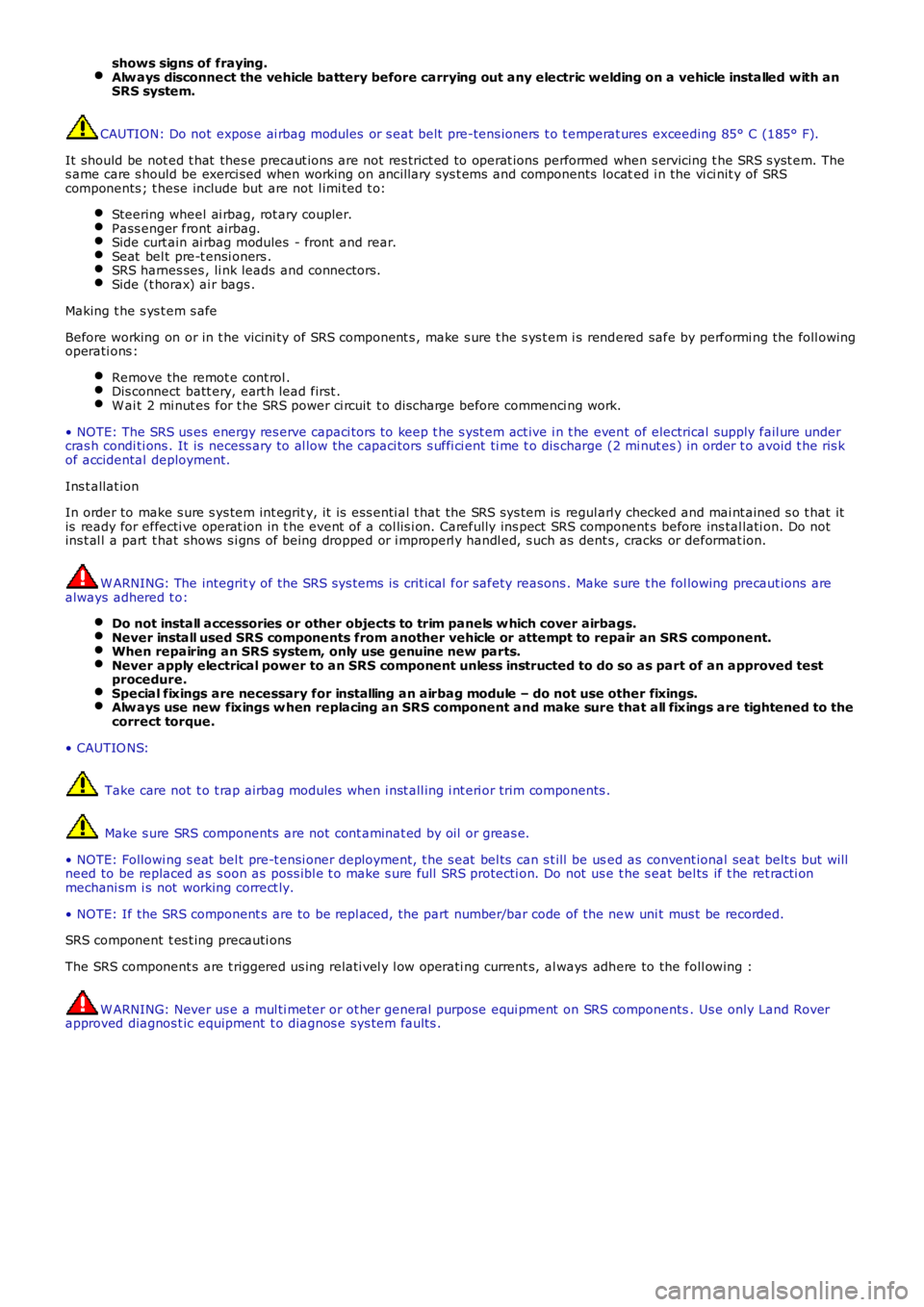
shows signs of fraying.Alw ays disconnect the vehicle battery before carrying out any electric welding on a vehicle installed with anSRS system.
CAUTION: Do not expos e ai rbag modules or s eat belt pre-tens ioners t o t emperat ures exceeding 85° C (185° F).
It should be not ed t hat thes e precaut ions are not res trict ed to operat ions performed when s ervicing t he SRS s yst em. Thes ame care s hould be exerci sed when working on ancil lary sys t ems and components located i n the vi ci nit y of SRScomponents ; t hese include but are not l imi ted t o:
Steering wheel ai rbag, rot ary coupler.Pass enger front airbag.Side curt ain ai rbag modules - front and rear.Seat bel t pre-t ensi oners .SRS harnes ses , li nk leads and connectors.Side (t horax) ai r bags .
Making t he s ys t em s afe
Before working on or in t he vicini ty of SRS component s , make s ure t he s ys t em i s rendered safe by performi ng the foll owingoperati ons :
Remove the remot e cont rol .Dis connect batt ery, eart h lead first .W ai t 2 mi nut es for t he SRS power ci rcuit t o di scharge before commenci ng work.
• NOTE: The SRS us es energy res erve capaci tors to keep t he s yst em act ive i n t he event of electrical supply fail ure undercras h condi ti ons . It is necess ary to al low the capaci tors s uffi ci ent ti me t o dis charge (2 mi nut es ) in order t o avoid t he ris kof accidental deployment.
Ins t allat ion
In order to make s ure s ys tem int egrit y, it is ess enti al t hat the SRS sys tem is regularl y checked and mai nt ained s o t hat itis ready for effecti ve operat ion in t he event of a col lis i on. Carefully ins pect SRS component s before ins tal lati on. Do notins t al l a part t hat shows s i gns of being dropped or i mproperl y handl ed, s uch as dents , cracks or deformat ion.
W ARNING: The integrit y of the SRS sys tems is crit ical for safety reasons . Make s ure t he fol lowing precaut ions arealways adhered t o:
Do not install accessories or other objects to trim panels w hich cover airbags.Never install used SRS components from another vehicle or attempt to repair an SRS component.When repairing an SRS system, only use genuine new parts.Never apply electrical power to an SRS component unless instructed to do so as part of an approved testprocedure.Special fixings are necessary for installing an airbag module – do not use other fixings.Alw ays use new fixings w hen replacing an SRS component and make sure that all fixings are tightened to thecorrect torque.
• CAUTIO NS:
Take care not t o t rap airbag modules when i nst all ing i nt eri or trim components .
Make s ure SRS components are not cont aminat ed by oil or greas e.
• NOTE: Followi ng s eat bel t pre-t ensi oner deployment, t he s eat bel ts can s t ill be used as convent ional seat belt s but wil lneed to be replaced as s oon as poss i bl e t o make s ure full SRS protecti on. Do not us e t he s eat bel ts if t he ret racti onmechani sm i s not working correct ly.
• NOTE: If the SRS component s are to be repl aced, the part number/bar code of the new uni t mus t be recorded.
SRS component t es t ing precauti ons
The SRS component s are t riggered us ing relati vel y l ow operati ng current s, al ways adhere to the foll owing :
W ARNING: Never us e a mul ti meter or ot her general purpose equi pment on SRS components. Us e only Land Roverapproved diagnos t ic equipment t o diagnos e sys tem faul ts .
Page 142 of 3229
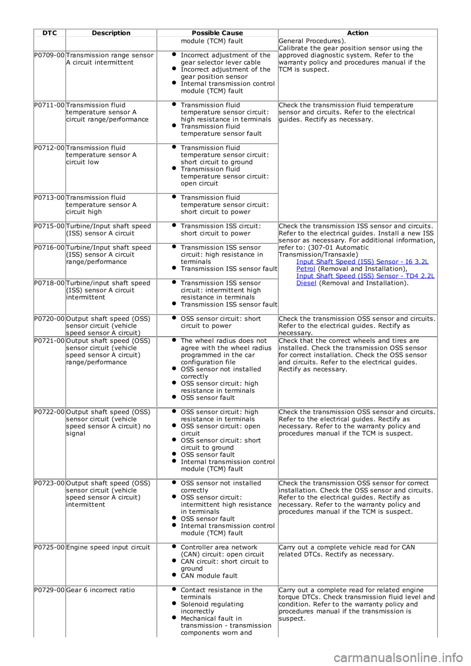
DT C
Description Possible Cause Action
modul e (TCM) fault General Procedures ).
Cal ibrat e t he gear pos it ion sens or us i ng the
approved di agnos ti c s ys t em. Refer to the
warrant y poli cy and procedures manual if t he
TCM is sus pect .
P0709-00
Trans mis s ion range sens or
A circui t int ermi tt ent Incorrect adjus tment of t he
gear s elector lever cabl e Incorrect adjus tment of t he
gear posi ti on s ens or Int ernal t rans mi ss i on cont rol
modul e (TCM) fault P0711-00
Trans mis s ion flui d
temperature s ens or A
circuit range/performance Transmis si on fluid
temperat ure s ens or ci rcuit :
hi gh res is t ance i n t ermi nal s Transmis si on fluid
temperat ure s ens or fault Check t he transmis s ion fluid temperat ure
sens or and ci rcuit s. Refer to t he elect rical
gui des . Recti fy as necess ary.
P0712-00 Trans mis s ion flui d
temperature s ens or A
circuit l ow Transmis si on fluid
temperat ure s ens or ci rcuit :
short ci rcuit t o ground Transmis si on fluid
temperat ure s ens or ci rcuit :
open circui t P0713-00
Trans mis s ion flui d
temperature s ens or A
circuit hi gh Transmis si on fluid
temperat ure s ens or ci rcuit :
short ci rcuit t o power P0715-00
Turbine/Input shaft speed
(ISS) s ens or A circui t Transmis si on ISS ci rcuit :
short ci rcuit t o power Check t he transmis s ion ISS s ens or and circuit s .
Refer to the el ect ri cal guides . Ins tal l a new ISS
sens or as neces sary. For addit ional i nformati on,
refer t o: (307-01 Aut omati c
Transmis s ion/Trans axle)
Input Shaft Speed (ISS) Sensor - I6 3.2L Pet rol (Removal and Ins t al lat ion),
Input Shaft Speed (ISS) Sensor - TD4 2.2L Di esel (Removal and Ins t allat ion).
P0716-00
Turbine/Input shaft speed
(ISS) s ens or A circui t
range/performance Transmis si on ISS s ens or
ci rcuit : high res i st ance in
terminals Transmis si on ISS s ens or fault
P0718-00
Turbine/input shaft speed
(ISS) s ens or A circui t
int ermi tt ent Transmis si on ISS s ens or
ci rcuit : int ermi tt ent hi gh
res is tance in terminals Transmis si on ISS s ens or fault
P0720-00
Output s haft s peed (OSS)
s ens or circuit (vehi cle
s peed s ens or A circuit ) OSS s ens or ci rcuit : s hort
ci rcuit t o power Check t he transmis s ion OSS s ens or and circui ts .
Refer to the el ect ri cal guides . Rect ify as
neces sary.
P0721-00 Output s haft s peed (OSS)
s ens or circuit (vehi cle
s peed s ens or A circuit )
range/performance The wheel radi us does not
agree wit h t he wheel radius
programmed in t he car
confi gurati on fi le OSS s ens or not ins tall ed
correctl y OSS s ens or ci rcuit : high
res is tance in terminals OSS s ens or fault Check t hat t he correct wheels and ti res are
ins tall ed. Check t he transmis si on OSS s ensor
for correct ins t al lat ion. Check t he OSS s ensor
and ci rcuit s. Refer to t he elect rical guides.
Rect ify as neces s ary.
P0722-00 Output s haft s peed (OSS)
s ens or circuit (vehi cle
s peed s ens or A circuit ) no
s ignal OSS s ens or ci rcuit : high
res is tance in terminals OSS s ens or ci rcuit : open
ci rcuit OSS s ens or ci rcuit : s hort
ci rcuit t o ground OSS s ens or fault
Int ernal t rans mi ss i on cont rol
modul e (TCM) fault Check t he transmis s ion OSS s ens or and circui ts .
Refer to the el ect ri cal guides . Rect ify as
neces sary. Refer t o t he warranty pol icy and
procedures manual if t he TCM is s us pect.
P0723-00 Output s haft s peed (OSS)
s ens or circuit (vehi cle
s peed s ens or A circuit )
int ermi tt ent OSS s ens or not ins tall ed
correctl y OSS s ens or ci rcuit :
intermit t ent hi gh res is t ance
in t ermi nals OSS s ens or fault
Int ernal t rans mi ss i on cont rol
modul e (TCM) fault Check t he transmis s ion OSS s ens or for correct
ins tall ati on. Check the OSS s ens or and circuit s .
Refer to the el ect ri cal guides . Rect ify as
neces sary. Refer t o t he warranty pol icy and
procedures manual if t he TCM is s us pect.
P0725-00 Engi ne s peed input ci rcuit Cont roll er area network
(CAN) circui t: open circui t CAN circuit : s hort circui t to
ground CAN module fault Carry out a compl ete vehicle read for CAN
relat ed DTCs. Recti fy as neces sary.
P0729-00 Gear 6 incorrect rati o Cont act resi s tance in the
terminals Sol enoi d regulat ing
incorrectl y Mechanical fault i n
trans mi ss i on - transmis s ion
component s worn and Carry out a compl ete read for related engi ne
torque DTCs . Check trans mi ss i on fl uid l evel and
condit ion. Refer t o the warrant y poli cy and
procedures manual if t he t rans mis s ion i s
sus pect .
Page 143 of 3229
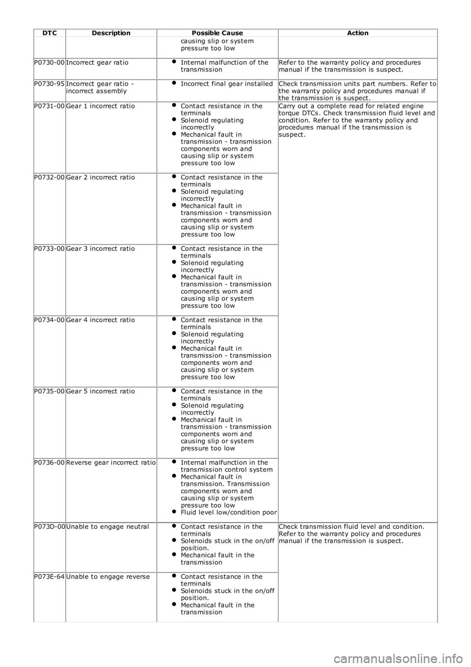
DT C
Description Possible Cause Action
caus ing s li p or s ys t em
press ure too low
P0730-00 Incorrect gear rat io Int ernal malfuncti on of the
trans mi ss i on Refer to the warrant y pol icy and procedures
manual i f the t rans mis s ion is s us pect.
P0730-95 Incorrect gear rat io -
incorrect as s embl y Incorrect final gear ins t al led Check t rans mis s ion unit s part numbers. Refer t o
the warrant y pol icy and procedures manual if
the t rans mi ss ion is s us pect .
P0731-00 Gear 1 incorrect rati o Cont act resi s tance in the
terminals Sol enoi d regulat ing
incorrectl y Mechanical fault i n
trans mi ss i on - transmis s ion
component s worn and
caus ing s li p or s ys t em
press ure too low Carry out a compl ete read for related engi ne
torque DTCs . Check trans mi ss i on fl uid l evel and
condit ion. Refer t o the warrant y poli cy and
procedures manual if t he t rans mis s ion i s
sus pect .
P0732-00 Gear 2 incorrect rati o Cont act resi s tance in the
terminals Sol enoi d regulat ing
incorrectl y Mechanical fault i n
trans mi ss i on - transmis s ion
component s worn and
caus ing s li p or s ys t em
press ure too low P0733-00
Gear 3 incorrect rati o Cont act resi s tance in the
terminals Sol enoi d regulat ing
incorrectl y Mechanical fault i n
trans mi ss i on - transmis s ion
component s worn and
caus ing s li p or s ys t em
press ure too low P0734-00
Gear 4 incorrect rati o Cont act resi s tance in the
terminals Sol enoi d regulat ing
incorrectl y Mechanical fault i n
trans mi ss i on - transmis s ion
component s worn and
caus ing s li p or s ys t em
press ure too low P0735-00
Gear 5 incorrect rati o Cont act resi s tance in the
terminals Sol enoi d regulat ing
incorrectl y Mechanical fault i n
trans mi ss i on - transmis s ion
component s worn and
caus ing s li p or s ys t em
press ure too low P0736-00
Reverse gear i ncorrect rat io Int ernal malfuncti on in the
trans mi ss i on cont rol s ys t em Mechanical fault i n
trans mi ss i on. Trans mi ss i on
component s worn and
caus ing s li p or s ys t em
press ure too low Fl uid l evel low/condi ti on poor
P073D-00
Unabl e t o engage neut ral Cont act resi s tance in the
terminals Sol enoi ds st uck in t he on/off
pos it ion. Mechanical fault i n the
trans mi ss i on Check t rans mis s ion flui d level and condit ion.
Refer to the warrant y pol icy and procedures
manual i f the t rans mis s ion is s us pect.
P073E-64 Unabl e t o engage revers e Cont act resi s tance in the
terminals Sol enoi ds st uck in t he on/off
pos it ion. Mechanical fault i n the
trans mi ss i on
Page 144 of 3229
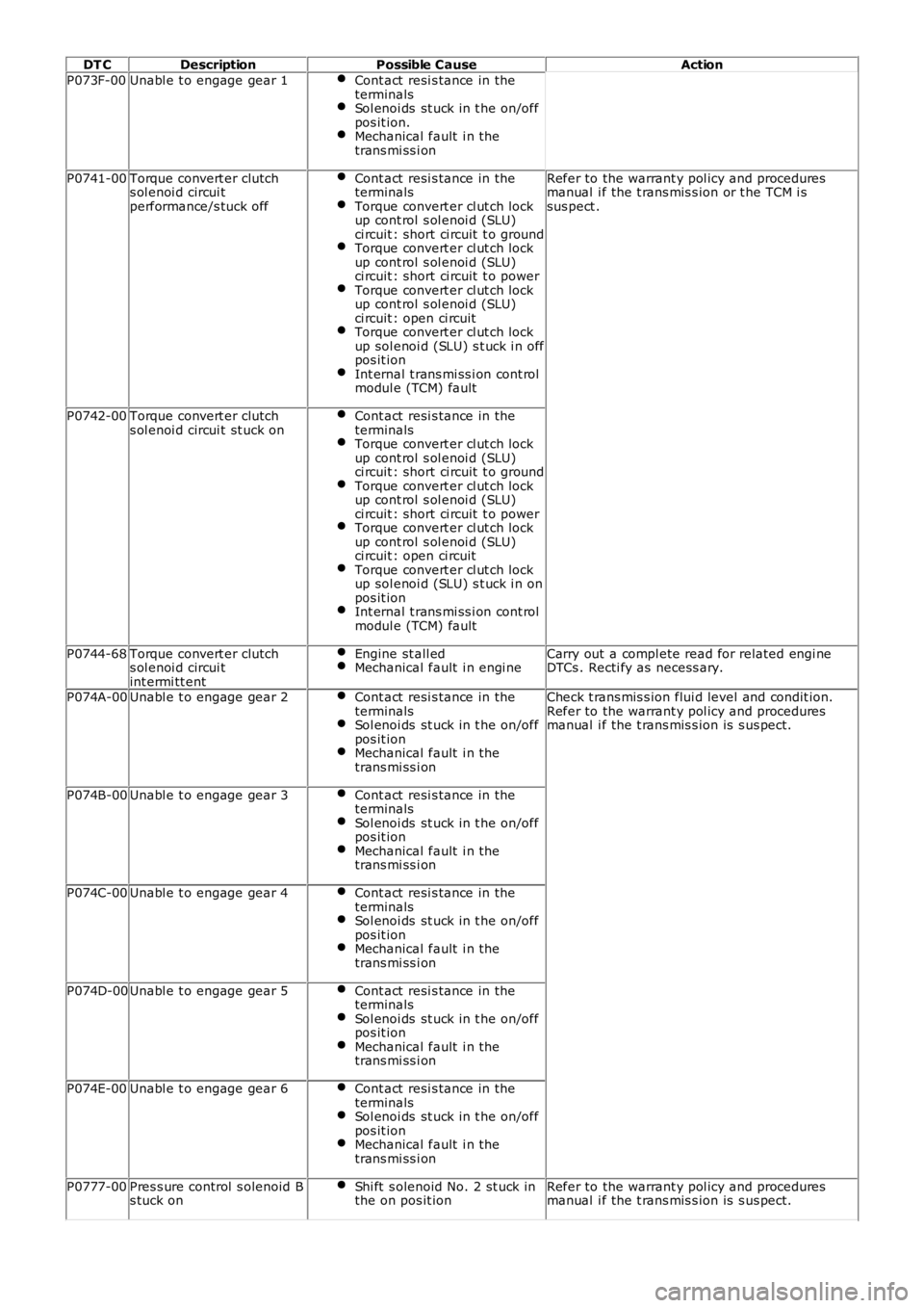
DT C
Description Possible Cause Action
P073F-00 Unabl e t o engage gear 1 Cont act resi s tance in the
terminals Sol enoi ds st uck in t he on/off
pos it ion. Mechanical fault i n the
trans mi ss i on P0741-00
Torque convert er clutch
s ol enoi d circui t
performance/s tuck off Cont act resi s tance in the
terminals Torque convert er cl ut ch lock
up cont rol s ol enoi d (SLU)
ci rcuit : short ci rcuit t o ground Torque convert er cl ut ch lock
up cont rol s ol enoi d (SLU)
ci rcuit : short ci rcuit t o power Torque convert er cl ut ch lock
up cont rol s ol enoi d (SLU)
ci rcuit : open ci rcuit Torque convert er cl ut ch lock
up sol enoi d (SLU) s t uck i n off
pos it ion Int ernal t rans mi ss i on cont rol
modul e (TCM) fault Refer to the warrant y pol icy and procedures
manual i f the t rans mis s ion or t he TCM i s
sus pect .
P0742-00 Torque convert er clutch
s ol enoi d circui t st uck on Cont act resi s tance in the
terminals Torque convert er cl ut ch lock
up cont rol s ol enoi d (SLU)
ci rcuit : short ci rcuit t o ground Torque convert er cl ut ch lock
up cont rol s ol enoi d (SLU)
ci rcuit : short ci rcuit t o power Torque convert er cl ut ch lock
up cont rol s ol enoi d (SLU)
ci rcuit : open ci rcuit Torque convert er cl ut ch lock
up sol enoi d (SLU) s t uck i n on
pos it ion Int ernal t rans mi ss i on cont rol
modul e (TCM) fault P0744-68
Torque convert er clutch
s ol enoi d circui t
int ermi tt ent Engine st all ed Mechanical fault i n engi ne Carry out a compl ete read for related engi ne
DTCs . Recti fy as necess ary.
P074A-00 Unabl e t o engage gear 2 Cont act resi s tance in the
terminals Sol enoi ds st uck in t he on/off
pos it ion Mechanical fault i n the
trans mi ss i on Check t rans mis s ion flui d level and condit ion.
Refer to the warrant y pol icy and procedures
manual i f the t rans mis s ion is s us pect.
P074B-00 Unabl e t o engage gear 3 Cont act resi s tance in the
terminals Sol enoi ds st uck in t he on/off
pos it ion Mechanical fault i n the
trans mi ss i on P074C-00
Unabl e t o engage gear 4 Cont act resi s tance in the
terminals Sol enoi ds st uck in t he on/off
pos it ion Mechanical fault i n the
trans mi ss i on P074D-00
Unabl e t o engage gear 5 Cont act resi s tance in the
terminals Sol enoi ds st uck in t he on/off
pos it ion Mechanical fault i n the
trans mi ss i on P074E-00
Unabl e t o engage gear 6 Cont act resi s tance in the
terminals Sol enoi ds st uck in t he on/off
pos it ion Mechanical fault i n the
trans mi ss i on P0777-00
Pres s ure control s olenoid B
s tuck on Shi ft s olenoid No. 2 st uck in
the on pos it ion Refer to the warrant y pol icy and procedures
manual i f the t rans mis s ion is s us pect.