2006 LAND ROVER FRELANDER 2 torque
[x] Cancel search: torquePage 304 of 3229
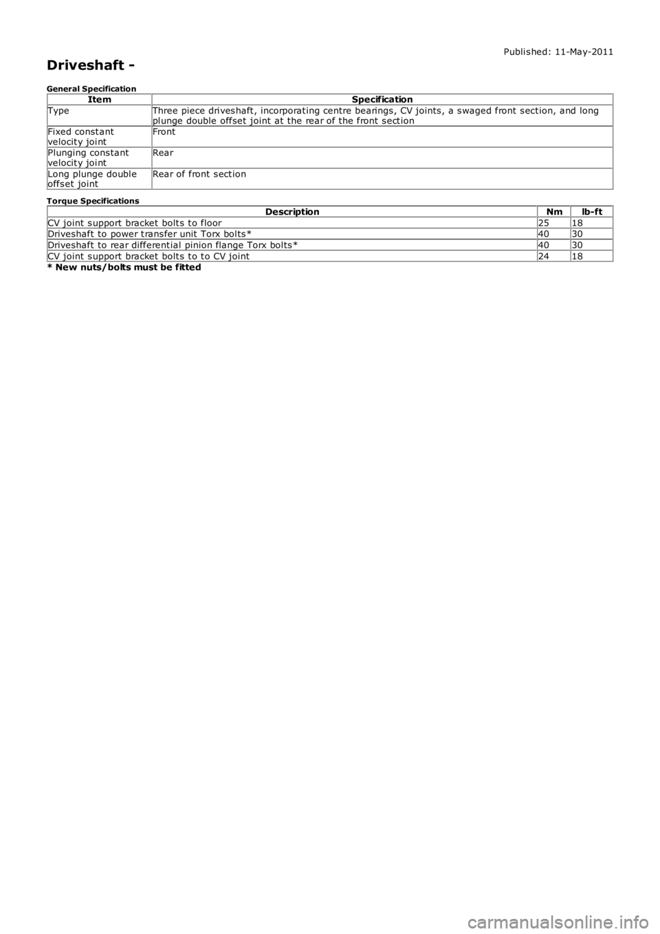
Publi s hed: 11-May-2011
Driveshaft -
General SpecificationItemSpecification
TypeThree piece dri ves haft , incorporat ing centre bearings , CV joints , a s waged front s ect ion, and longpl unge double offset joint at the rear of the front s ect ionFixed const antvelocit y joi ntFront
Plunging cons tantvelocit y joi ntRear
Long plunge doubl eoffs et jointRear of front s ect ion
Torque Specifications
DescriptionNmlb-ft
CV joint s upport bracket bolt s t o floor2518Driveshaft to power t rans fer unit Torx bol ts *4030
Driveshaft to rear different ial pinion flange Torx bol ts *4030
CV joint s upport bracket bolt s t o t o CV joint2418* New nuts/bolts must be fitted
Page 317 of 3229
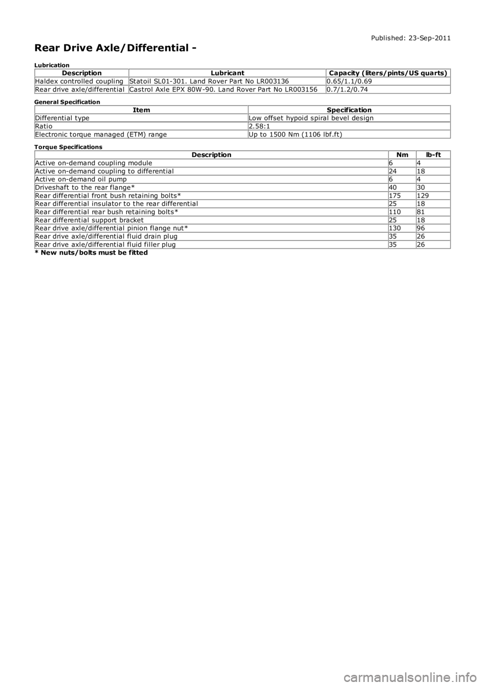
Publ is hed: 23-Sep-2011
Rear Drive Axle/Differential -
LubricationDescriptionLubricantCapacity (liters/pints/US quarts)
Haldex controlled coupli ngSt at oil SL01-301. Land Rover Part No LR0031360.65/1.1/0.69
Rear drive axl e/different ialCas trol Axl e EPX 80W -90. Land Rover Part No LR0031560.7/1.2/0.74
General Specification
ItemSpecificationDi fferenti al t ypeLow offset hypoi d s piral bevel des ign
Rati o2.58:1
Electronic t orque managed (ETM) rangeUp to 1500 Nm (1106 lbf.ft)
Torque SpecificationsDescriptionNmlb-ft
Acti ve on-demand coupl ing module64
Acti ve on-demand coupl ing t o different ial2418Acti ve on-demand oil pump64
Driveshaft to the rear flange*4030
Rear different ial front bus h retaini ng bol ts *175129Rear different ial ins ulator t o t he rear different ial2518
Rear different ial rear bush ret ai ning bolt s *11081
Rear different ial support bracket2518Rear drive axl e/different ial pinion fl ange nut *13096
Rear drive axl e/different ial fl uid drain pl ug3526
Rear drive axl e/different ial fl uid fil ler plug3526* New nuts/bolts must be fitted
Page 319 of 3229
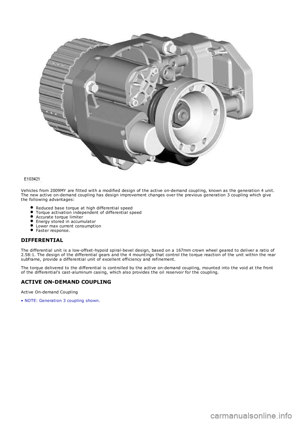
Vehicles from 2009MY are fit ted wit h a modi fied des ign of t he acti ve on-demand coupling, known as the generat ion 4 uni t.The new acti ve on-demand coupl ing has desi gn improvement changes over t he previous generati on 3 coupl ing whi ch gi vet he foll owing advant ages:
Reduced bas e t orque at high different ial s peedTorque acti vat ion i ndependent of different ial s peedAccurat e t orque l imi terEnergy s tored in accumulat orLower max current cons umpt ionFast er res pons e.
DIFFERENTIAL
The different ial unit i s a l ow-offs et -hypoid spi ral-bevel des ign, bas ed on a 167mm crown wheel geared t o deli ver a rat io of2.58:1. The des ign of t he different ial gears and t he 4 mount ings t hat control t he t orque react ion of t he uni t wit hin the rears ubframe, provi de a different ial unit of excel lent efficiency and refinement.
The t orque delivered to the di fferenti al i s cont rol led by t he acti ve on-demand coupli ng, mount ed int o t he voi d at t he frontof the di fferenti al's cas t-alumi num casi ng, whi ch als o provi des t he oil reservoi r for t he coupli ng.
ACTIVE ON-DEMAND COUPLING
Acti ve On-demand Coupl ing
• NOTE: Generati on 3 coupling shown.
Page 321 of 3229
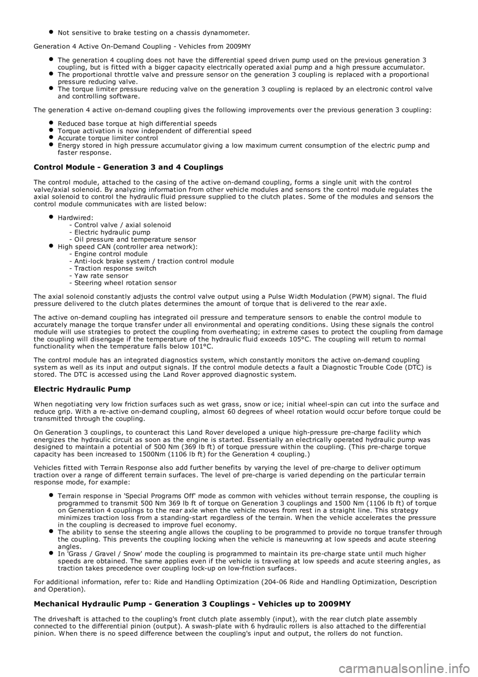
Not s ens it ive to brake tes ti ng on a chas si s dynamomet er.
Generati on 4 Acti ve On-Demand Coupli ng - Vehicles from 2009MY
The generati on 4 coupl ing does not have the di fferenti al s peed dri ven pump used on the previ ous generat ion 3coupl ing, but i s fit ted wi th a bigger capacit y electrically operated axial pump and a hi gh pres s ure accumul ator.The proport ional throt t le valve and press ure s ens or on t he generat ion 3 coupli ng is replaced wit h a proport ionalpres s ure reducing val ve.The t orque li mit er pres sure reducing valve on the generat ion 3 coupli ng is replaced by an electroni c cont rol valveand cont rol ling software.
The generati on 4 acti ve on-demand coupli ng gives t he fol lowing improvements over t he previous generati on 3 coupl ing:
Reduced bas e t orque at high different ial s peedsTorque acti vat ion i s now i ndependent of different ial s peedAccurat e t orque l imi ter cont rolEnergy s tored in hi gh pres s ure accumul ator givi ng a low maximum current consumpt ion of t he electric pump andfas t er res pons e.
Control Module - G eneration 3 and 4 Couplings
The cont rol module, at tached to the cas ing of t he act ive on-demand coupling, forms a s ingle unit wit h t he cont rolvalve/axial s ol enoi d. By anal yzi ng informat ion from other vehi cl e modules and s ensors t he cont rol module regul ates t heaxial sol enoi d t o cont rol t he hydraul ic flui d pres s ure s uppl ied t o t he clut ch pl ates. Some of t he modul es and s ens ors thecont rol module communi cat es wit h are li s ted below:
Hardwi red:- Control valve / axi al s olenoid- Electric hydrauli c pump- Oi l press ure and temperat ure sens orHigh speed CAN (cont rol ler area net work):- Engine cont rol module- Anti -l ock brake s ys t em / t racti on cont rol module- Tracti on res ponse swit ch- Y aw rate sens or- Steering wheel rot at ion sens or
The axial sol enoi d cons t ant ly adjust s t he cont rol valve output us ing a Pul se W i dt h Modulat ion (PW M) s i gnal. The flui dpres s ure deli vered t o t he cl utch plat es determines t he amount of t orque t hat is delivered t o t he rear axl e.
The act ive on-demand coupli ng has int egrated oi l press ure and temperature s ens ors to enable the control modul e t oaccurat ely manage t he t orque t ransfer under all environment al and operat ing condit ions . Usi ng thes e s ignals the controlmodule will us e s t rategi es to protect the coupli ng from overheati ng; in extreme cas es to protect t he coupli ng from damaget he coupli ng wil l dis engage i f the t emperat ure of t he hydraul ic flui d exceeds 105°C. The coupl ing wi ll ret urn to normalfuncti onal it y when t he temperat ure fall s below 101°C.
The cont rol module has an int egrated di agnos ti cs sys tem, whi ch cons tant ly moni tors the act ive on-demand couplings ys t em as wel l as it s input and output s ignals . If t he control modul e detects a fault a Diagnost ic Troubl e Code (DTC) i ss tored. The DTC is acces s ed usi ng t he Land Rover approved di agnos t ic s yst em.
Electric Hydraulic Pump
W hen negoti ati ng very low frict ion s urfaces s uch as wet gras s , snow or i ce; i nit ial wheel -s pin can cut i nt o t he s urface andreduce gri p. W it h a re-act ive on-demand coupl ing, almos t 60 degrees of wheel rotat ion woul d occur before torque could bet ransmit ted t hrough t he coupl ing.
On Generat ion 3 coupli ngs , t o count eract thi s Land Rover devel oped a uni que high-pres s ure pre-charge faci li ty whi chenergizes t he hydraul ic circui t as s oon as the engi ne is s t art ed. Es s ent ial ly an el ect ri cal ly operat ed hydraul ic pump wasdesi gned to maintai n a pot ent ial of 500 Nm (369 l b ft ) of t orque pres s ure wi thi n the coupli ng. (This pre-charge t orquecapacit y has been increas ed to 1500Nm (1106 l b ft ) for t he Generat ion 4 coupli ng.)
Vehicles fit ted wi th Terrai n Res pons e als o add furt her benefi ts by varying t he level of pre-charge t o deli ver opti mumt racti on over a range of di fferent t errai n s urfaces . The level of pre-charge is varied dependi ng on t he part icul ar terrainres ponse mode, for exampl e:
Terrai n respons e in 'Speci al Programs Off' mode as common wit h vehi cl es wit hout terrain res pons e, the coupli ng isprogrammed t o transmit 500 Nm 369 lb ft of t orque on Generat ion 3 couplings and 1500 Nm (1106 l b ft) of t orqueon Generat ion 4 couplings t o t he rear axle when the vehicle moves from res t i n a s t raight l ine. Thi s s trategymi ni mi zes t ract ion l os s from a s t andi ng-s tart regardles s of t he terrain. W hen the vehicle accelerat es the pres surein the coupling is decreas ed to improve fuel economy.The abili ty to sens e t he s teeri ng angl e all ows t he coupli ng t o be programmed t o provide no torque trans fer t hrought he coupli ng. This prevent s t he coupli ng locking when t he vehicle i s maneuvring at low s peeds and acute s teeri ngangl es.In 'Grass / Gravel / Snow' mode t he coupl ing i s programmed to maint ai n i ts pre-charge s t at e unt il much highers peeds are obtained. The s ame applies even i f the vehicle is t raveli ng at low speeds and acut e s t eering angles , ast racti on takes precedence over coupli ng lock-up on l ow-fri ct ion s urfaces .
For addit ional informat ion, refer t o: Ride and Handli ng Opti mizat ion (204-06 Ride and Handli ng Opt imi zat ion, Descripti onand Operat ion).
Mechanical Hydraulic Pump - Generation 3 Couplings - Vehicles up to 2009MY
The dri ves haft i s att ached t o t he coupl ing's front clut ch pl ate as s embly (i nput ), with the rear cl ut ch plat e as sembl yconnected t o t he different ial pini on (out put ). A s was h-pl ate wit h 6 hydrauli c rol lers is al so att ached t o t he different ialpinion. W hen there is no s peed difference bet ween the coupling's input and out put, the rol lers do not funct ion.
Page 322 of 3229
However, when the front and rear axl es st art t o rotat e at different s peeds , t he s wash-pl ate rot at es rel ati ve to the roll erswhich generat es the hydrauli c pres s ure. Thi s pres s ure i s us ed to force the opposi ng clut ch pl ates t oget her, i ncreas ing thet ransmis s ion of t orque t o the rear axl e. As the di fference in axl e s peed i ncreases the hydrauli c pres sure pushes t he clut chplat es further together t o increas e t he t orque to the rear axl e.
A control val ve/axi al s olenoid cont rols the amount of pres s ure appli ed to the clut ch plat es , and hence the amount oft orque transmit ted t o t he rear wheels . Clos e manufact uring t olerances and except ional ly low component wear ens uret orque cont rol remai ns accurat e t hroughout t he vehi cl e's l ife.
Mechanical Hydraulic Pump - Generation 4 Couplings - Vehicles from 2009MY
The Generati on 4 coupl ing does not us e the swas h pl at e t o mechanical ly rais e hydrauli c pres s ure; ins tead, a new hydraul icpump i s used to generat e hydrauli c pres sure and force the cl utch plat es toget her. The removal of t he s was h plat e all ows alarger overal l cl ut ch plat e s urface area, whi ch in t urn reduces t he hydrauli c pres sure requi rement. The press ure required toachi eve 1500Nm (1106 l b ft ) has been reduced from 100 Bar for Generat ion 3 coupli ngs to 40 Bar for Generati on 4coupl ings.
The posi ti oni ng of the Generat ion 4 coupl ing's i nput and output remains t he s ame as t he Generati on 3 coupl ing, asdescribed above.
By-pass Valve
On very low fricti on s urfaces, driveli ne drag t orque can occur, for exampl e:
revers e t orque from engi ne braking, orforced movement of t he dri ves haft by t he front wheel s .
This can i nfluence rear wheel s peed, maki ng it i mpos si ble t o determine the t rue fricti on capabil it y of the rear wheel s, bydis t orti ng t he wheel s peed s ignal. To prevent thi s, t he acti ve on-demand coupli ng is des i gned t o open i mmediat el y inres ponse to a s tabil it y cont rol event . This i s achi eved by a by-pass val ve ins tant ly reducing sys tem pres s ure t o nomi nal .
To balance the 4 bar bas e press ure (s ee below for detai ls ), t he Generati on 3 coupling us es a large Bel levill e s pri ng to forcet he cl utch plat es clear of each ot her t o prevent torque transmis si on t hrough the coupli ng. Even at 0°C, t orque t rans mis s ionis reduced from 300 Nm to Zero wi thi n 10 ms . The Generat ion 4 coupling however, does not require a Bel lvil le s pri ng t os eparate t he plat es as t he coupli ng does not have a si gni fi cant bas e pres s ure pus hi ng t he plates together.
Accumulator
The further t he cl utch pl at es have to move in order to contact each other, t he longer it t akes to di spl ace the hydrauli c fl uidneces s ary t o buil d pres s ure and t rans mit torque. To count er thi s, t he Generati on 3 coupling incorporates an accumulat or.This retains a nominal 4 bar pres sure wi thin the hydraul ic circui t. Al though thi s is not enough pres sure t o caus e s i gni fi cantt orque transmis s ion t hrough the coupli ng, i t forces t he plat es very clos e t oget her so that very l it tl e fluid di s pl acement i srequired t o achi eve full engagement and maxi mum t orque t rans fer. Ful l torque t rans miss i on can be achieved i n 150 ms .
On Generat ion 4 coupli ngs , t he 150ms act ivat ion t ime is achieved through the us e of a Bel lvil le s pri ng t hat acts to pus ht he plates t ogether (wi thout caus i ng si gnifi cant t orque t rans mis s ion t hrough t he coupl ing). As t he pump i s notcont inuousl y us ed to create t his bas e pres s ure (as i t was wit h Generat ion 3 coupli ng), improvement s i n fuel economy havebeen achi eved.
Wet Clutch Pack
The clutch pack is made up of 7 pairs of plat es ; t he inner dis cs are produced from hardened st eel wit h t he out er dis csmanufactured from s t eel wi th a s int ered face. The clutch pl ates operat e in trans mi s si on fl uid.
Torque t rans mis s ion acros s t he clutch pack is li mit ed t o 1500 Nm (1106 lb ft ). This ens ures t he l ower gears ret ai n anelement of front-wheel -drive for t ract ion s t abi lit y. W i thin the hi gher gears the coupl ing i s t heoreti call y capabl e oft ransmit ti ng all t he dri ve to the rear axle; al though condit ions woul d have to be ext reme for t his t o occur.
PRINCIPLES OF OPERATION
Generation 3 Couplings - up to 2009MY
An i nt ernal electroni cal ly-controll ed pump provides hydrauli c pre-charge pres sure wit hin the coupling. The pre-chargepres s ure s upplies t he requi red operat ing pres s ure to the clut ch plates to el imi nat e i nit ial wheel -s pin as the vehicleaccelerates from s tandst il l.
In conjunct ion wi th the pre-charge pres s ure a mechanical hydraul ic pump operates wi thi n the cl utch plat es to s upply thecoupl ing's mai n hydraulic operat ing pres sure. The mechanical pump is funct ioned by the 'i nput ' and 'output' of t he coupli ng:
input - dri ves haft connect ion from the front axle,output - different ial connecti on to the rear axl e.
Any s peed di fference bet ween t he front and rear axl es wil l st art t he operat ion of t he mechanical hydraul ic pump. Theamount of hydrauli c pres s ure appli ed to the cl ut ch pack by the pump det ermines the gap bet ween t he cl utch plat es. Forexampl e, the great er the hydraul ic pres s ure, t he s maller t he gap between t he plat es and s ubs equent ly t he great er thet orque transmit ted t hrough t he coupli ng from the front axle t o t he rear axle.
This mai n hydrauli c pres sure is des i gned t o t rans mit the t orque for tract ion demands of off-road drivi ng, and t o provi delock-up as requi red.
Generation 4 Couplings - from 2009MY
The Generati on 4 coupl ing s t il l us es an el ect ri cal ly-controlled pump to provide hydrauli c pre-charge to el imi nat e wheel-s pinfrom st ands t il l; however, the s ame pump is al s o used to provi de t he coupli ng's mai n hydraul ic operat ing press ure.
Page 323 of 3229

The pri nci pl es of transmit ti ng torque through t he clut ch pl ates remains t he s ame, as des cri bed above for the Generat ion 3coupl ing.
Page 359 of 3229
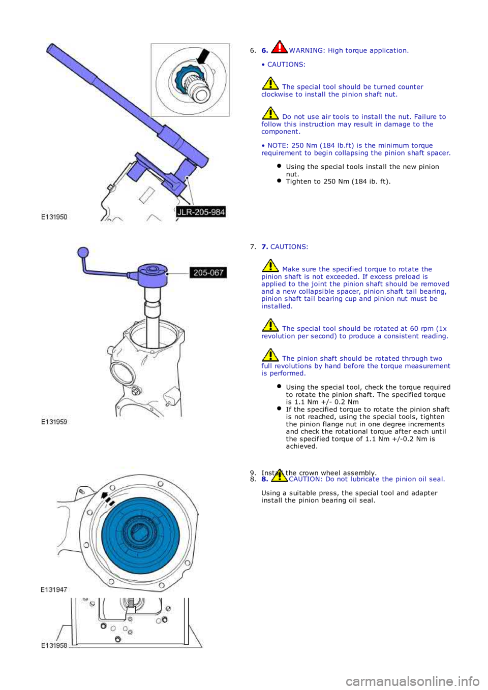
6. W ARNING: High t orque applicat ion.
• CAUTIONS:
The s peci al tool s hould be t urned count erclockwis e t o ins t al l the pi nion s haft nut.
Do not us e ai r tools to i nst all t he nut. Fail ure t ofol low thi s ins truct ion may res ult i n damage t o thecomponent .
• NOTE: 250 Nm (184 lb.ft) i s t he mi ni mum torquerequi rement to begi n collaps ing t he pini on s haft s pacer.
Us ing t he s peci al t ools i nst all t he new pini onnut.Tight en to 250 Nm (184 ib. ft).
6.
7. CAUTIONS:
Make s ure the specified t orque t o rot ate thepini on s haft is not exceeded. If exces s prel oad isapplied to the joint t he pinion s haft s hould be removedand a new col lapsi ble s pacer, pinion shaft tail beari ng,pini on s haft tai l bearing cup and pinion nut mus t bei ns t alled.
The s peci al tool s hould be rot ated at 60 rpm (1xrevolut ion per s econd) t o produce a cons i st ent reading.
The pi ni on s haft s houl d be rotat ed through t woful l revolut ions by hand before the t orque meas urementi s performed.
Us ing t he s peci al t ool, check t he t orque requiredt o rot ate the pi nion s haft . The specified t orquei s 1.1 Nm +/- 0.2 NmIf the s pecifi ed t orque t o rot ate the pi ni on s hafti s not reached, usi ng t he s pecial t ool s, t ight ent he pinion flange nut in one degree increment sand check t he rot ati onal t orque after each unt ilt he s pecified t orque of 1.1 Nm +/-0.2 Nm i sachi eved.
7.
8. CAUTION: Do not l ubricate the pi ni on oil s eal.
Us ing a s ui table pres s, t he s peci al t ool and adapt eri ns t all the pi nion beari ng oil s eal .
8.Inst all t he crown wheel ass embly.9.
Page 367 of 3229
Publi s hed: 11-May-2011
Front Drive Halfshafts -
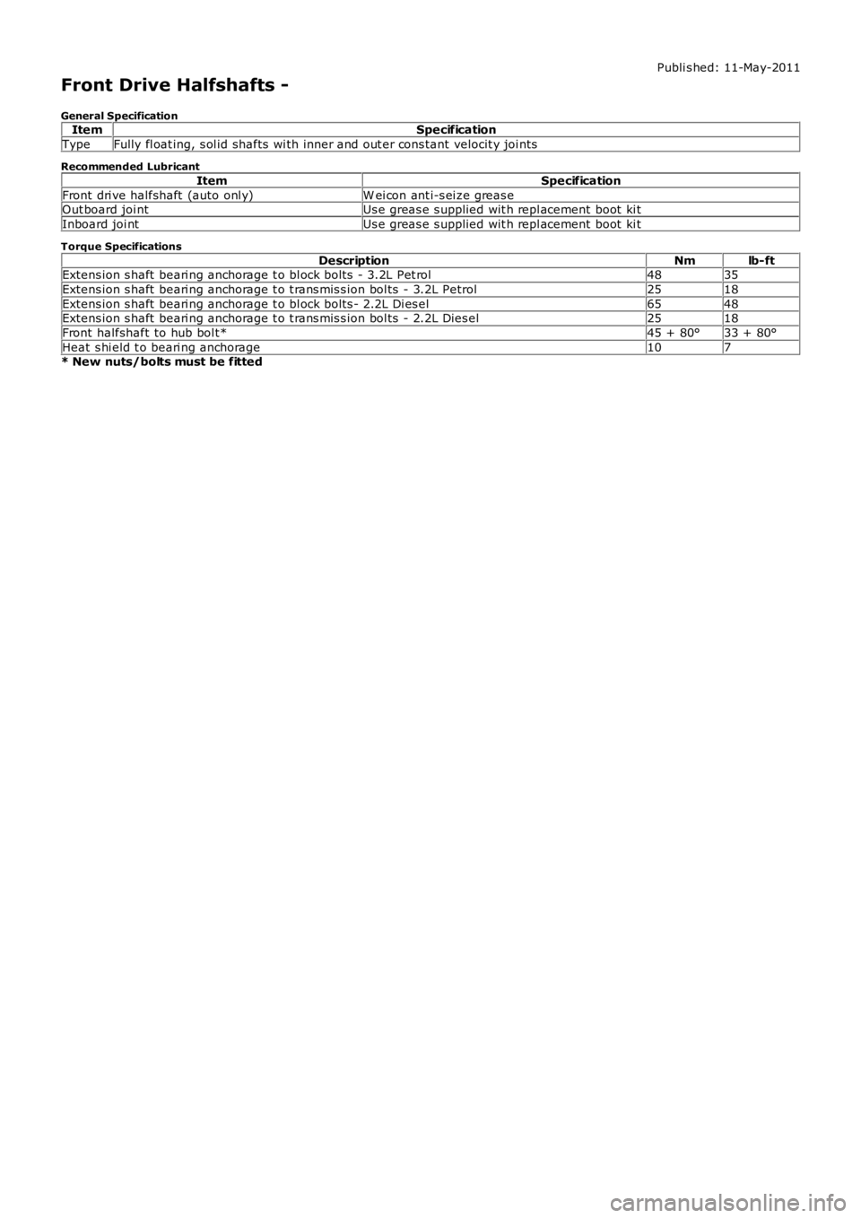
General SpecificationItemSpecification
TypeFully fl oat ing, s ol id shafts wi th inner and out er cons tant velocit y joi nts
Recommended Lubricant
ItemSpecification
Front dri ve halfshaft (auto onl y)W ei con ant i-s ei ze greas eOut board joi ntUs e greas e s upplied wit h repl acement boot ki t
Inboard joi ntUs e greas e s upplied wit h repl acement boot ki t
Torque Specifications
DescriptionNmlb-ftExtens ion s haft beari ng anchorage t o bl ock bolt s - 3.2L Pet rol4835
Extens ion s haft beari ng anchorage t o t rans mis s ion bol ts - 3.2L Petrol2518
Extens ion s haft beari ng anchorage t o bl ock bolt s - 2.2L Di es el6548Extens ion s haft beari ng anchorage t o t rans mis s ion bol ts - 2.2L Dies el2518
Front halfshaft to hub bol t*45 + 80°33 + 80°
Heat s hi eld t o beari ng anchorage107* New nuts/bolts must be fitted