Page 564 of 3229
Publi s hed: 11-May-2011
Steering Linkage -
Torque SpecificationsDescriptionNmlb-ft
Tie-rod end nut7052
Tie-rod l ocki ng nut5541
Page 570 of 3229
Publi s hed: 11-May-2011
Steering Column -
General SpecificationItemSpecification
Upper columnManual column wit h t ilt and reach adjust ment
Torque Specifications
DescriptionNmlb-ft
Heats hiel d lower bolt s (2) to s t eel pi ni on t ower3.22.3Heats hiel d upper bolt (1) t o plas ti c s eal2.41.77
St eering column bol ts2518
St eering wheel bol t4835Univers al joi nt to st eering gear bolt *2518
* New nuts/bolts must be fitted
Page 584 of 3229
Publi s hed: 11-May-2011
Steering Column Switches -
Torque SpecificationsDescriptionNmlb-ft
St eering column swi tch Torx s crews1.51.0
Page 603 of 3229

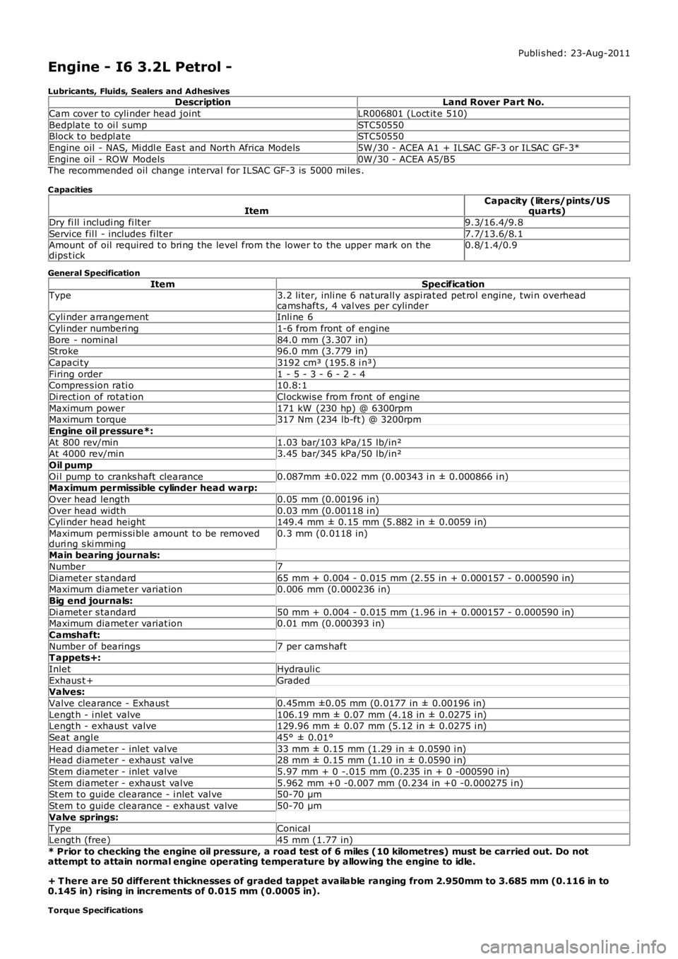
Publi s hed: 23-Aug-2011
Engine - I6 3.2L Petrol -
Lubricants, Fluids, Sealers and AdhesivesDescriptionLand Rover Part No.
Cam cover to cyli nder head jointLR006801 (Loct it e 510)
Bedplate to oi l s umpSTC50550Block t o bedpl ateSTC50550
Engine oil - NAS, Mi ddl e Eas t and Nort h Africa Models5W /30 - ACEA A1 + ILSAC GF-3 or ILSAC GF-3*
Engine oil - ROW Models0W /30 - ACEA A5/B5The recommended oil change i nterval for ILSAC GF-3 is 5000 mi les .
C apacities
ItemCapacity (liters/pints/USquarts)
Dry fi ll i ncludi ng fi lt er9.3/16.4/9.8
Service fil l - includes fi lt er7.7/13.6/8.1Amount of oil required t o bri ng the level from the lower to the upper mark on thedips t ick0.8/1.4/0.9
General Specification
ItemSpecificationType3.2 li ter, inli ne 6 nat urall y aspi rat ed pet rol engine, twi n overheadcams haft s, 4 val ves per cylinderCyli nder arrangementInli ne 6
Cyli nder numberi ng1-6 from front of engine
Bore - nominal84.0 mm (3.307 in)St roke96.0 mm (3.779 in)
Capaci ty3192 cm³ (195.8 i n³)
Firing order1 - 5 - 3 - 6 - 2 - 4Compres s ion rati o10.8:1
Di recti on of rotat ionCl ockwis e from front of engi ne
Maximum power171 kW (230 hp) @ 6300rpmMaximum t orque317 Nm (234 lb-ft ) @ 3200rpm
Engine oil pressure*:
At 800 rev/min1.03 bar/103 kPa/15 lb/in²At 4000 rev/min3.45 bar/345 kPa/50 lb/in²
Oil pump
Oi l pump to cranks haft clearance0.087mm ±0.022 mm (0.00343 i n ± 0.000866 i n)Maximum permissible cylinder head w arp:
Over head length0.05 mm (0.00196 i n)
Over head widt h0.03 mm (0.00118 i n)Cyli nder head height149.4 mm ± 0.15 mm (5.882 in ± 0.0059 i n)
Maximum permi s si ble amount t o be removedduri ng s ki mmi ng0.3 mm (0.0118 in)
Main bearing journals:
Number7
Di amet er s tandard65 mm + 0.004 - 0.015 mm (2.55 in + 0.000157 - 0.000590 in)Maximum diamet er variat ion0.006 mm (0.000236 in)
Big end journals:
Di amet er s tandard50 mm + 0.004 - 0.015 mm (1.96 in + 0.000157 - 0.000590 in)Maximum diamet er variat ion0.01 mm (0.000393 i n)
Camshaft:
Number of bearings7 per cams haftT appets+:
InletHydrauli c
Exhaus t +GradedValves:
Valve clearance - Exhaus t0.45mm ±0.05 mm (0.0177 in ± 0.00196 in)
Lengt h - i nlet valve106.19 mm ± 0.07 mm (4.18 in ± 0.0275 i n)Lengt h - exhaus t valve129.96 mm ± 0.07 mm (5.12 in ± 0.0275 i n)
Seat angl e45° ± 0.01°
Head diamet er - inlet valve33 mm ± 0.15 mm (1.29 in ± 0.0590 i n)Head diamet er - exhaus t val ve28 mm ± 0.15 mm (1.10 in ± 0.0590 i n)
St em diamet er - inlet valve5.97 mm + 0 -.015 mm (0.235 in + 0 -000590 i n)
St em diamet er - exhaus t val ve5.962 mm +0 -0.007 mm (0.234 in +0 -0.000275 i n)St em t o guide clearance - i nlet val ve50-70 µm
St em t o guide clearance - exhaus t valve50-70 µm
Valve springs:TypeConical
Lengt h (free)45 mm (1.77 in)
* Prior to checking the engine oil pressure, a road test of 6 miles (10 kilometres) must be carried out. Do notattempt to attain normal engine operating temperature by allowing the engine to idle.
+ T here are 50 different thicknesses of graded tappet available ranging from 2.950mm to 3.685 mm (0.116 in to0.145 in) rising in increments of 0.015 mm (0.0005 in).
Torque Specifications
Page 604 of 3229

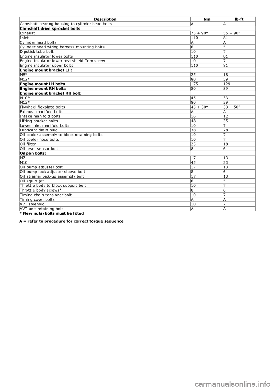
DescriptionNmlb-ft
Cams haft beari ng hous ing to cyli nder head bolt sAA
Camshaft drive sprocket boltsExhaus t75 + 90°55 + 90°
Inlet11081
Cyli nder head bolt sAACyli nder head wiring harnes s mount ing bolt s65
Di ps t ick t ube bol t107
Engine i ns ulat or lower bolt s11081Engine i ns ulat or lower heat s hield Torx s crew107
Engine i ns ulat or upper bolt s11081
Engine mount bracket LH:M8*2518
M12*8059
Engine mount LH bolts175129Engine mount RH bolts8059
Engine mount bracket RH bolt:
M10*4533M12*8059
Flywheel flexplat e bolt s45 + 50°33 + 50°
Exhaus t manifold bol tsAAIntake manifold bol ts1612
Lifti ng bracket bol ts4835
Lower inlet mani fold bol ts107Lubricant drain plug3828
Oi l cooler as sembl y t o block ret aining bol ts107
Oi l cooler hos e bolt s107Oi l fil ter2518
Oi l level s ensor bolt86
Oil pan bolts:M71713
M104533
Oi l pump adjus ter bolt1713Oi l pump lock adjus ter s leeve bolt86
Oi l st rai ner pi ck-up ass embly bol t1713
Oi l squirt jet65Throt tl e body to block support bolt107
Throt tl e body s crews*86
Timing chain t ensi oner bolt107Timing cover bolt sAA
VVT s olenoid107
VVT unit retai ni ng boltAA* New nuts/bolts must be fitted
A = refer to procedure for correct torque sequence
Page 607 of 3229
A Rear End Ancillary Drive (READ) s yst emTwo fabricated s t ainles s s t eel t win s kin exhaust manifoldsA 3-pos ition Variable Intake Sys t em (VIS)An advanced Engine Management Syst em (EMS) incorporat ing elect ronic t hrot tle controlFour cat alyt ic converters
Technical data
DESCR IPT IO NT YPEConfigurationInline 6-cylinderO utput171 kW at 6200 rpmT orque320 Nm at 3200 rpmDisplacement3192 cm³Stroke/bore96.0 mm/84.0 mmCompression ratio10.8:1Firing order1-5-3-6-2-4Approximate weight180 kg (including int ake pipe, exhaus t manifold, alt ernator and oil)
ItemPart NumberDescriptionA-Torque (Nm)B-Power (kW )
CYLINDER BLOCK COMPONENTS
The main cylinder block components are:
Cylinder blockConnect ing rods and pis tonsPist on cooling jet sGenerat orGear hous ingThermos tat hous ingCranks haft Pos it ion (CKP) s ensorKnock s ens orsCoolant pumpCoolant inlet pipe
Cylinder Numbering
The cylinders are numbered as shown below, wit h cylinder 1 at t he front of the engine.
Page 625 of 3229

For addit ional information, refer t o: Elect ronic Engine Cont rols (303-14A Elect ronic Engine Controls - I6 3.2L Pet rol, Des cript ion andOperation).
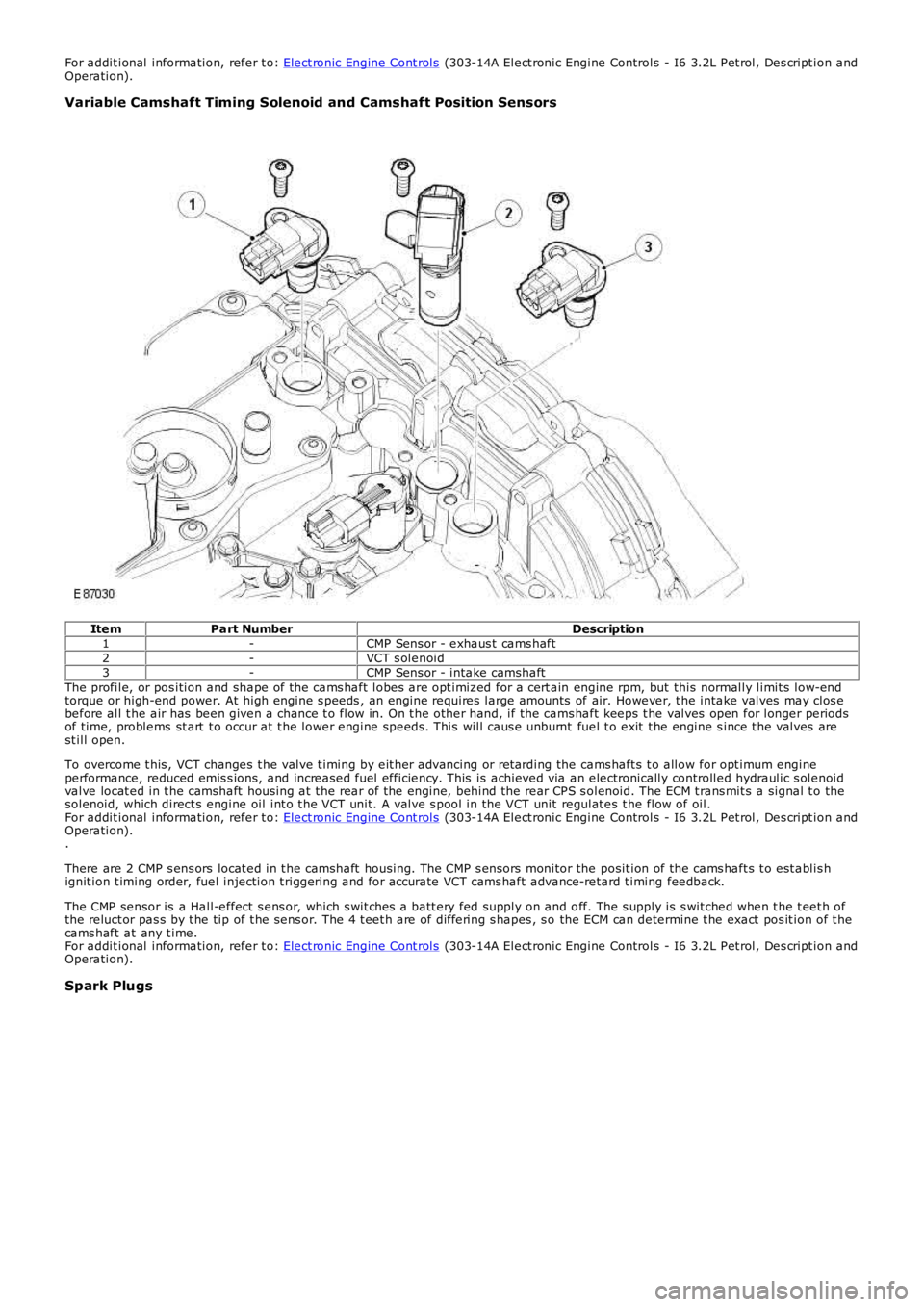
Variable Camshaft Timing Solenoid and Camshaft Position Sensors
ItemPart NumberDescription1-CMP Sens or - exhaus t cams haft2-VCT s olenoid3-CMP Sens or - intake camshaftThe profile, or pos ition and shape of the cams haft lobes are opt imiz ed for a cert ain engine rpm, but this normally limit s low-endtorque or high-end power. At high engine s peeds , an engine requires large amounts of air. However, t he intake valves may clos ebefore all t he air has been given a chance t o flow in. On t he other hand, if the cams haft keeps t he valves open for longer periodsof time, problems st art t o occur at t he lower engine speeds . This will caus e unburnt fuel t o exit t he engine s ince t he valves arest ill open.
To overcome t his , VCT changes t he valve t iming by eit her advancing or ret arding the cams haft s t o allow for opt imum engineperformance, reduced emis s ions, and increased fuel efficiency. This is achieved via an electronically controlled hydraulic s olenoidvalve locat ed in t he camshaft housing at t he rear of t he engine, behind the rear CPS s olenoid. The ECM t rans mit s a signal t o thesolenoid, which direct s engine oil int o t he VCT unit. A valve s pool in the VCT unit regulat es t he flow of oil.For addit ional information, refer t o: Elect ronic Engine Cont rols (303-14A Elect ronic Engine Controls - I6 3.2L Pet rol, Des cript ion andOperation)..
There are 2 CMP s ens ors locat ed in t he camshaft housing. The CMP s ensors monitor the posit ion of the cams haft s t o est ablis hignit ion t iming order, fuel injection t riggering and for accurate VCT cams haft advance-retard t iming feedback.
The CMP sensor is a Hall-effect s ens or, which s wit ches a batt ery fed supply on and off. The s upply is s wit ched when t he t eet h ofthe reluct or pas s by t he tip of t he sens or. The 4 t eet h are of differing s hapes , s o the ECM can determine t he exact pos it ion of t hecams haft at any t ime.For addit ional information, refer t o: Elect ronic Engine Cont rols (303-14A Elect ronic Engine Controls - I6 3.2L Pet rol, Des cript ion andOperation).
Spark Plugs
Page 670 of 3229
T orque:
16 Nm 9.
T orque:
16 Nm 10.
Install the l ifting brackets.
Torque: 48 Nm 11.
Secure t he cylinder head wiri ng harness.
12.