2006 LAND ROVER FRELANDER 2 towing
[x] Cancel search: towingPage 14 of 3229
Publi s hed: 11-May-2011
General Information - Standard Workshop Practices
Des cript ion and Operat ion
Vehicle in Workshop
W hen working on a vehicl e in the workshop al ways make sure t hat :
W here practi cable, t he parking brake is appli ed and t he wheel s are securely chocked to prevent t he vehi cl e movingforwards or backwards .W henever pos si ble, t he ignit ion key i s removed before any work is carried out on t he vehi cle.If the engine i s t o be run, t here i s adequat e vent il ati on, or an extract ion hos e i s us ed to remove exhaus t fumes.There i s adequat e room to rais e the vehicle and remove t he wheel s , if neces s ary.Fender covers are al ways ins tal led i f any work i s to be carri ed out in t he engine compart ment.W here practi cable, t he batt ery i s dis connected if worki ng on the engi ne, underneath t he vehicle, or if t he vehi cl e i srai sed.
• CAUTIO NS:
Prior to dis connect ing the bat tery, refer to the El ect ri cal Secti on of this manual - Bat tery dis connect ion/connect ion.For addit ional informat ion, refer t o: Specificati ons (414-01 Bat t ery, Mount ing and Cables , Speci ficat ions).
W hen el ect ri c arc wel ding on a vehi cl e, al ways dis connect t he generator wi ri ng to prevent t he pos si bili ty of a s urgeof current caus i ng damage to the i nternal component s of the generat or.
If us i ng welding equipment on t he vehicle, a s uit abl e fire exti nguis her is readily avail able.
Battery - General
• CAUTIO NS:
Prior to carrying out any procedures which i nvol ve dis connect ing/ or connecti ng the bat tery, refer t o t he ElectricalSect ion of t his manual - Batt ery di sconnect ion/connect ion.For addit ional informat ion, refer t o: Specificati ons (414-01 Bat t ery, Mount ing and Cables , Speci ficat ions).
A di s charged bat tery condit ion may have been caus ed by an electrical short ci rcuit . If t his condit ion exis t s there wil lbe an apparentl y li ve circuit on the vehicle even when al l normal circuit s are s wit ched off. This can cause arcing when t hejumper cables are connect ed.
W hi le it i s not recommended that the vehicl e is jump s t art ed, i t is recognized t hat thi s may occas ionall y be t he onl ypracti cal way t o mobi lize a vehi cl e. Prior t o at tempt ing a jump s t art , reference must be made to the El ect ri cal Secti on oft hi s manual - Jump St art ing.
Followi ng jump s tart ing of a dis abl ed vehi cle, the di s charged bat tery mus t be checked for s erviceabili ty and recharged offt he vehi cl e as s oon as poss ibl e t o avoi d permanent damage.
Do not rel y on t he generator t o res t ore a di s charged bat tery. For a generat or t o recharge a batt ery, it woul d take i n exces sof eight hours cont inuous dri vi ng wi th no addi ti onal loads placed on t he batt ery.
Always make s ure that t he jumper cabl es are adequate for the tas k.Always make s ure that t he s lave batt ery i s of the same vol tage as t he vehicle bat tery. The bat teries mus t beconnected i n paral lel.Always make s ure that s wit chabl e electric circui ts are s wi tched off before connecti ng jumper cabl es. This reducest he ri sk of arci ng occurring when the final connecti on is made.
Towing the Vehicle
W ARNING: W hen t owing i s neces sary, reference mus t be made to the Jacki ng, Lift ing and Towing Secti on of thi sManual .
W hen t he vehicle i s being t owed dock the remote cont rol and s wit ch on the ignit ion. (s t eering l ock releas ed and warni ngli ght s i ll uminated). Onl y t hen wil l the s t eering, turn s ignal lamps , horn and s t op lamps be operat ional. Fail ure t o followt hes e i nst ructi ons may res ult in pers onal injury. It mus t be noted that wit h t he engine not running, t he power s t eering andbrake boost er wil l be inoperat ive t herefore, great er effort wil l be needed t o s t eer t he vehicle and apply the brakes .
General Installation Instructions
Component removal
W henever pos si ble, clean component s and the surroundi ng area before removal .
Blank off openings expos ed by component removal .Followi ng dis connecti on, s eal fuel, oil or hydrauli c li nes i mmediat ely us ing sui table bl anki ng plugs or caps .Seal open ends of expos ed oil ways us i ng sui table tapered hardwood pl ugs or cons pi cuous pl as t ic pl ugs .Immediat el y a component i s removed, place it i n a sui table contai ner; us e a s eparate cont ai ner for each componentand it s as s ociat ed part s .
Page 169 of 3229

Publi s hed: 11-May-2011
Jacking and Lifting - Vehicle Recovery
Des cript ion and Operat ion
Towing Points
CAUTION: The s ingle towi ng poi nts at t he front and rear of t he vehi cl e are des igned for vehicl e recovery purpos esonly and mus t NOT be used to t ow a trail er or caravan.
The front towi ng eye is acces s ibl e aft er releas ing t he 2 t oggle fast eners s ecuring the t owing eye acces s panel andremovi ng the panel.
CAUTION: Ens ure t hat during t owing, the towi ng att achment does not contact t he bumper.
The rear t owing eye i s acces si ble after rel eas i ng the 2 toggle fas teners securi ng the towing eye access panel and removingt he panel.
CAUTION: This t owing eye s hould onl y be us ed for t owing another vehi cl e or for recovery purpos es .
Towing the vehicle on four wheels
• W ARNINGS:
Ens ure t hat the remote cont rol remai ns docked whil s t the vehicle is being towed. Removi ng the remot e cont rol wi llengage t he s t eering l ock, which wi ll prevent the vehicle from s t eering correct ly.
If the engine cannot be run whi ls t t he vehi cl e i s bei ng t owed, t here wi ll be no power as si s tance for t he s teeri ng orbrakes. Thi s wil l res ult in greater effort bei ng required to st eer or sl ow t he vehi cl e, and greatl y increas ed s toppingdis t ances.
• CAUTIO NS:
The vehicle s hould onl y be t owed wit h four wheels on the ground. Towing wi th two wheel s on t he ground wi ll res ultin serious damage t o t he trans mi s si on.
The vehicle s hould onl y be t owed for a maxi mum of 80 km (50 mil es), at a maximum s peed of 80 km/h (50 mph).Towing for a great er di st ance, or at a higher s peed may res ult i n s eri ous damage t o t he t rans mis s ion.
• NOTE: The recommended recovery met hod is to rais e al l four wheel s.
Towing procedure
1. The vehi cl e s houl d be parked on firm level ground, wi th t he park brake on, and the gear s el ect or in P if an aut omati cgearbox is fit t ed.
2. Secure the towing at t achment from the recovery vehicle to the front t owing eye.
CAUTION: Leavi ng the ignit ion s wi tched on for extended peri ods wil l caus e the bat tery t o drai n.
3. Dock the remote cont rol, and s wi tch on t he igni ti on.
4. Appl y t he foot brake, and s el ect neutral.
5. W i th the foot brake s t ill appli ed, releas e the park brake.
Page 170 of 3229
6. The vehi cl e can now be t owed a maxi mum of 80 km (50 mil es) at a maxi mum speed of 80 km/h (50 mph).
7. Upon arrival at t he des ti nat ion, ensure wherever pos s ibl e that t he vehi cl e i s par
ked on firm l evel ground.
8. Appl y t he park brake, and place t he s el ect or lever into the P pos i ti on.
9. Swit ch off t he ignit ion, and remove t he remote control. W ARNING: Use ext reme caut ion when det aching towing equi pment . Vehi cle movement is po
s s ible which can res ult i n
s erious i njuri es.
10. Remove the t owing at tachment from t he t owing eye.
Lashing Points
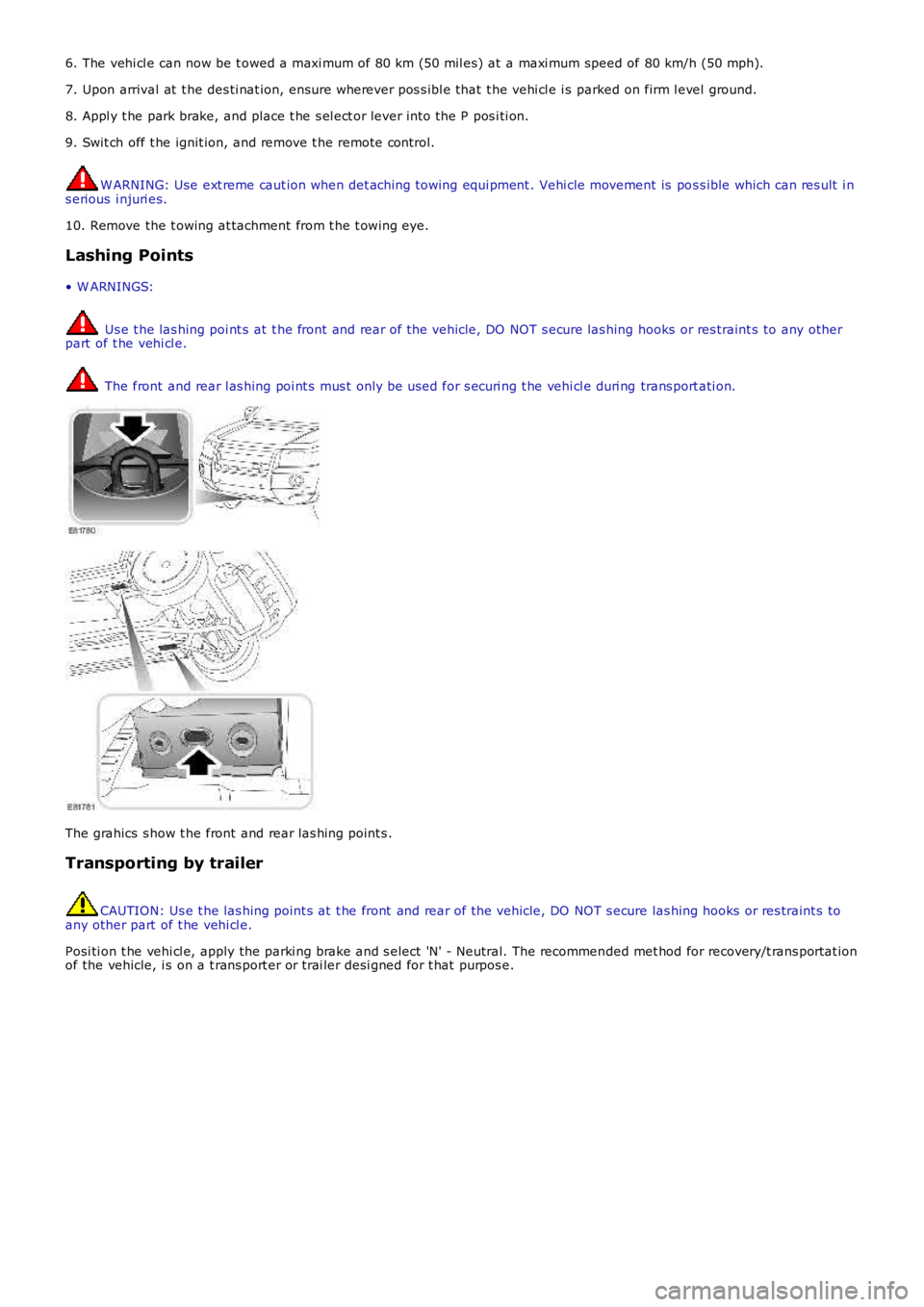
• W ARNINGS: Us e t he las hing poi nt s at t he front and rear of the vehicle, DO NOT s ecure las hing
hooks or res traint s to any other
part of t he vehi cl e. The front and rear l as hing poi nt s mus t only be used for s ecuri ng t he vehi cl e duri ng
trans port ati on.The grahics s how t he front and rear las hing point s .
Transporting by trailer CAUTION: Us e t he las hing point s at t he front and rear of the vehicle, DO NOT s ecure
las hing hooks or res traint s to
any other part of t he vehi cl e.
Posi ti on t he vehi cl e, apply the parki ng brake and s elect 'N' - Neutral. The recommen ded met hod for recovery/t rans portat ion
of the vehicle, i s on a t rans port er or t rai ler desi gned for t hat purpos e.
Page 648 of 3229
Interpretation of the Results
• NOTE: Due t o t he poss ibi li ty of l oos e carbon t hat has become t rapped between t he valve face and seat effect ing thepres s ure readi ngs , when carryi ng out a compres s ion t est and cyli nders are found to have low press ures , ins t al l the s parkplugs , road t est t he vehicle and re-t est the s us pect cyl inders . If the correct pressures are rest ored, no further acti on isrequired.
The indicat ed compress i on pres sures are cons idered wi thi n s pecificati on if t he l owest readi ng cyl inder is wi thi n 75% of t hehighest reading.
If the cyli nder pres s ures are found t o be l ow, carry out a l eakdown t est to det ermi ne the locat ion of t he faul t (i f anyleakback can be heard through t he engine breat her sys tem s uspect the pi st on rings , if any leakback can be heard throught he inlet s ys tem sus pect t he i nl et val ve or seat , if any leakback can be heard through the exhaus t mani fold sus pect t heexhaus t val ve or s eat . If t he meas urements for t wo cyl inders next t o each ot her are bot h t oo low then i t is very likely thatt he cyl inder head gas ket bet ween them is burnt t hrough. Thi s can als o be recognized by t races of engi ne oil in the coolantand/or cool ant i n t he engi ne oil ).
Oil Consump tion Test
The amount of oi l an engi ne uses will vary wit h t he way t he vehi cl e is driven i n addit ion t o normal engine-t o-enginevariat ion. This i s es pecial ly t rue during t he fi rs t 16,100 km (10,000 mil es) when a new engine i s bei ng broken i n or unt ilcert ai n i nt ernal components become condit ioned. Vehicles us ed i n heavy-dut y operati on may us e more oil . The fol lowingare exampl es of heavy-duty operat ion:
Trai ler towi ng appl icati onsSevere loading appli cat ionsSust ained high speed operat ion
Engi nes need oi l to lubri cat e t he fol lowing internal component s :
Cylinder block cyl inder wallsPis t ons and pi st on ringsInt ake and exhaus t val ve s temsInt ake and exhaus t val ve guidesAll i nt ernal engi ne component s
W hen t he pis t ons move downward, a t hi n film of oil i s left on the cyli nder wal ls . As t he vehi cl e is operated, s ome oil i sals o drawn int o t he combus t ion chambers pas t the i ntake and exhaus t valve s tem s eal s and burned.
The fol lowing are examples of condi ti ons that can affect oil consumpt ion rates :
Engi ne s izeOperat or driving habit sAmbient t emperaturesQuali ty and vi scos it y of oi lEngi ne is bei ng run in an overfil led condit ion (check t he oil level at least five minutes after a hot s hutdown wi th thevehi cl e parked on a level surface. The oi l level s hould not be above the top of t he cros s-hatched area and t he l et t er"F" i n FULL).
Operat ion under varyi ng condi ti ons can frequent ly be mi sl eadi ng. A vehi cl e t hat has been run for s everal t housand miles ons hort t rips or i n below-freezi ng ambient temperat ures may have cons umed a "normal" amount of oil . However, whenchecking t he engine oil l evel , it may meas ure up to the full mark on t he oil l evel indicator due t o dil uti on (condens ati onand fuel ) in t he engine crankcas e. The vehi cl e t hen might be driven at high s peeds on the hi ghway where t he condens at ionand fuel boil off. The next t ime t he engi ne oil is checked it may appear that a l it er of oi l was us ed i n about 160 km (100mi les ). Oi l cons umpti on rat e is about one l it er per 2,400 km (1,500 mil es).
Make s ure t he s elected engine oi l meets manufact urer s pecificati on and t he recommended API performance cat egory "SG"and SAE vis cos i ty grade as s hown in t he vehicle O wner's Gui de. It is al s o important t hat t he engine oi l i s changed at t heint ervals s peci fi ed for t he t ypi cal operati ng condi ti ons .
The fol lowing di agnos t ic procedure i s us ed to det ermi ne t he s ource of excess i ve oi l cons umpti on.
• NOTE: Oi l us e i s normal ly great er during the first 16,100 km (10,000 mi les ) of servi ce. As mil eage i ncreas es , oil us edecreas es . High s peed dri vi ng, towing, high ambi ent temperat ure and ot her factors may res ult in great er oil use.
1. Defi ne exces si ve cons umpti on, s uch as t he number of miles driven per li ter of oil used. Al so det ermine cust omersdriving habit s , such as s us tai ned hi gh s peed operat ion, t owing, ext ended i dle and other cons iderat ions.1.
2. Verify t hat the engine has no ext ernal oi l leaks as descri bed under Engine Oi l Leaks i n thi s s ect ion.2.
3. Carry out an oil cons umpti on t es t :
Run t he engi ne to normal operati ng t emperature. Swi tch engine OFF and al low oi l to drain back for at l eas tfi ve mi nut es .W i th vehi cl e parked on l evel s urface, check t he engi ne oil l evel.If required, add engine oil t o s et level exactl y t o t he FULL mark.Record t he vehi cl e mi leage.Ins t ruct the cus tomer t o return for a l evel check after driving t he vehi cle as us ual for 1,610 km (1000 mi les ).Check t he oil l evel under t he s ame condit ions and at the same locat ion as the i nit ial check.
3.
• NOTE: If the oi l cons umpti on rat e is unaccept abl e go t o St ep 4.
4. Check t he Posi ti ve Crankcas e Vent ilat ion (PCV) sys t em. Make sure t he s ys t em i s not pl ugged.4.
5. Check for pl ugged oi l drain-back holes i n t he cyl inder head and cyli nder bl ock.5.
6. Carry out a cyl inder compress ion tes t. Refer t o t he Compres s ion Tes t procedure in thi s s ect ion. Thi s can help6.
Page 664 of 3229
T orque:
10 Nm Connect t he purge l ine.
14.
Inst all t he lower int ake manifol d bolt s .
T orque: 10 Nm 15.
Inst all t he air cleaner out let pipe.
16.
Inst all t he engi ne undershi eld.
Refer t o: Engi ne Unders hi eld (501-02 Front End Body Panel s ,
Removal and Ins tall ati on).
17.
Inst all t he front unders hiel d.
18.
Inst all t he front towing eye cover.
19.
Inst all t he air cleaner as s embly.
Refer t o: Air Cleaner (303-12B Intake Ai r Dis tribut ion and Fil tering -
TD4 2.2L Dies el, Removal and Inst all ati on).
20.
Inst all t he engi ne cover.
Refer t o: Engi ne Cover - I6 3.2L Pet rol (501-05 Int eri or Trim and
Ornament ati on, Removal and Ins tal lat ion).
21.
Connect t he batt ery ground cable.
Refer t o: Specificati ons (414-00 Bat tery and Charging Sys tem -
General Informat ion, Specificati ons).
22.
Check and top-up the coolant.
23.
Page 986 of 3229
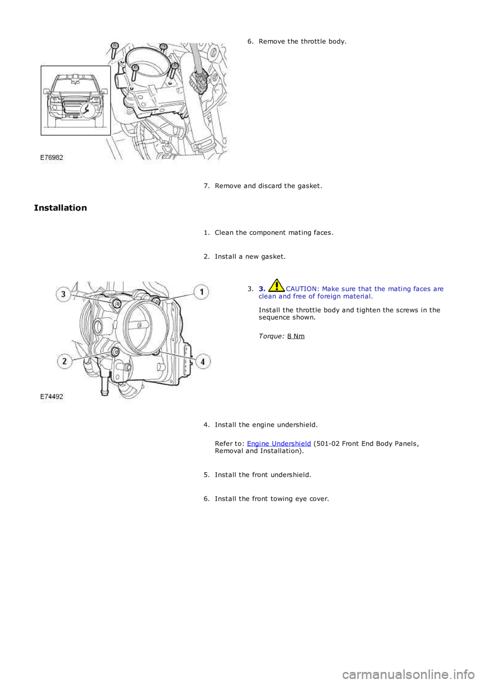
Remove t he thrott le body.
6.
Remove and dis card t he gas ket .
7.
Installation
Clean t he component mat ing faces .
1.
Inst all a new gas ket.
2. 3. CAUTION: Make s ure that the mati ng faces are
clean and free of foreign materi al.
Inst all t he thrott le body and t ighten the s crews i n t he
s equence s hown.
T orque: 8 Nm 3.
Inst all t he engi ne undershi eld.
Refer t o: Engi ne Unders hi eld (501-02 Front End Body Panel s ,
Removal and Ins tall ati on).
4.
Inst all t he front unders hiel d.
5.
Inst all t he front towing eye cover.
6.
Page 1108 of 3229
however remain i ll uminated.
A ‘st all recovery’ event is the onl y s tat e when t he Stop/St art s yst em wil l permit t he engine t o be s t art ed when thet ransmis s ion i s in gear; hence t he requirement for t he cl utch pedal to be full y depres sed. If the s t all recovery fai ls and t heengi ne does not res tart, t he dri ver wi ll be reques ted vi a t he Mess age Center t o ‘s elect neutral ’ to at t empt anot her rest art .
If the engine does not res t art aft er thi s request t he ‘st all recovery’ mode wil l ti me-out and deact ivate. At t his point t he‘Eco’ i con in t he i ns t rument panel wi ll exti ngui sh and the light s usual ly as s ociat ed wi th an engi ne st all wi ll il lumi nat e. As ares ult t he dri ver will be requi red to perform a convent ional engi ne res tart.
Alt hough st all recovery i s a feat ure of t he St op/Start sys t em i t is pos si ble for it t o acti vat e i ndependent ly from t heStop/St art parameters . For exampl e:
If the St op/Start s ys t em has been deact ivated by the driver st all recovery wi ll s ti ll funct ion.Stal l recovery wil l act ivate at ambi ent temperat ures as l ow as (minus ) - 2°C, whereas the St op/Syst em operat ingt emperature threshold is above 4°C.Different t o t he operat ion of t he Stop/St art s yst em, s tal l recovery wil l st il l functi on when the vehicle is t owing;refer to the ‘Trail er Towi ng’ s ect ion.
• NOTE: As t he neces s ary cri teria will not have been sat is fi ed when t he vehi cl e i s at the beginning of a journey s t allrecovery wi ll not functi on. For exampl e, if t he vehi cl e s tal ls when l eavi ng the garage or driveway a convent ional engineres t art wi ll be required.
Trailer Towing
The Stop/St art s ys tem wil l aut omati cal ly di sabl e when t rail er light s are det ect ed by t he CJB via s ignals from t he t rail ermodule, t hi s informat ion i s t hen trans mi tt ed t o t he ECM. It i s not pos s ibl e for t he s ys t em t o det ect when a trai ler powerplug i s ins ert ed i n the vehicl e’s t owi ng s ocket s o it us es operat ion of t he trail er l ights as it s indi cat or.
The t rail er towing sys tem inhi bi ts St op/St art as i t is pos s ible that trail er power requirements could interfere wit h t heoperati on of the bat tery monit ori ng s ys t em. In parti cul ar, a t rai ler batt ery could revers e t he feed current t o t he vehicleduri ng an engi ne cranking event , t hi s coul d pos si bly:
Confus e t he bat t ery monit ori ng s ys t em i nto det ect ing an unreal is t ically smal l current at engi ne cranking.Rupture the fus e as sociat ed wit h t he t rail er modul e.
Climate Control System
• NOTE: The ‘ECON’ butt on has been renamed ‘A/C’ to prevent confus ion wi th the St op/St art s yst em ‘Eco’ s wit ch.
A number of changes have been made to the l ogi c and operati on of climat e control system, wit hi n a St op/St art cycle to:
maint ain occupant comfortprevent winds hi eld mis ti ngcons erve bat tery power.
This has been achi eved by the ATC (automat ic t emperat ure control) module monit oring and varyi ng, as necess ary variousclimate control funct ions wi thi n a St op/Start cycle.
In s ome circums t ances t he ATC has t he capabil it y to inhibit an engi ne s hut down or init iat e an engine rest art wit hi n aStop/St art cycle. Thi s i s achi eved by t he ATC module communi cat ing wit h t he CJB on the medi um s peed CAN. The variousoverri de functi ons the ATC has in a St op/St art cycl e are di s cus s ed bel ow:
Coolant temperat ure
The ATC module wil l i nhibit an engine shut down or i nit iat e an engine res t art wi thi n a St op/Start cycle if t he coolantt emperature fal ls below the calculat ed t hreshol d to s upport t he cabin t emperat ure s et by t he vehi cl e occupant s .
W i nds hiel d demis t ing
The variant of cli mate control fi tt ed t o the vehicl e influences t he s oft ware changes that have been made. For exampl e, thebase cl imat e-control s ys tem does not have a humi dit y s ens or, as us ed on a highline sys tem t o ini ti at e a winds hi elddemis t . Therefore, a calculat ion for demis ti ng the winds hi eld i s made us ing t he s ignals from t he rai n s ens or and ambientt emperature s ens or. Us i ng the probabi lit y t hat windshi eld mis ti ng wil l occur if i t is raining and t he ambi ent t emperat ure i scool , the ATC wil l presume a wi nds hiel d demis t is required and s tart the engine when i n a St op/St art cycl e.
Evaporat or temperat ure the main cause of windshi eld mis ti ng is al s o monit ored and t he high-line cl imat e cont rol s yst emwil l periodicall y cool t he evaporat or as neces s ary t o reduce mi s ti ng during a Stop/St art cycl e. The sys tem operates thewinds hield demis t s hut ter and i f the evaporator i s wet t he shut ter wi ll remai n clos ed for a few seconds after an engineres t art unti l the vapor is di ss ipat ed.
If the driver sel ect s eit her ‘programmed defros t ’ or t he ‘wi ndshi el d heater’ i t is as s umed t hat a qui ck demis t of thewinds hield is requi red. Therefore, t he ATC vi a the CJB will ei ther: i nhibit an engine shut down or i nit iat e an engine res t art .
Heater fan speed
Duri ng an engine s hutdown t he ATC monit ors cabin temperat ure and maint ai ns the fan speed at a l evel that wi ll cons erve,for as l ong as poss ibl e t he heat i n t he core of t he cabi n heat er. If the driver s elect s a hi gher fan s peed and the heatcannot be mai ntained i n t he heat er core, the engine will rest art .
Heated rear window and heated s eats
If the heated rear window or heated s eats are acti ve or act ivated during an engine shut down event t he power out put oft he relevant s ys t em wi ll be i nt errupted unt il the engi ne is rest art ed. The tell -t ale light i n t he relevant s wit ch wil lil lumi nat e t o i ndi cat e t he s ys t em i s act ive even t hough the s ys tem is recei vi ng no power. This feature is us ed t o conservebatt ery power.
Page 1295 of 3229
Reverse Lock-Out
If the s elector l ever is moved from N to R and t he vehi cl e i s travel li ng forwards , revers e s electi on is prevent ed if t hevehi cl e s peed is 11 km/h (6.8 mph) or more. W hen revers e lock-out is act ivated, t he cl utch (C3) is released wit houtenergizing sol enoid (SLC3), preventi ng t he transmis si on from sel ect ing reverse gear.
TRANSMISSION FAULT STATUS
If the TCM det ect s a fault wi th the t rans mi ss ion sys tem, it wi ll enter a defaul t (l imp home) mode to prevent furt herdamage to the trans mi ss i on and allow the vehicl e to be dri ven. If pos s ibl e revers e gear wil l be avai lable and al s o 3rd gearonly.
W hen a fault i s detected a high s peed CAN mes s age is s ent from the TCM and is recei ved by the i nst rument clus ter. Theins t rument clus ter il lumi nat es t he MIL (i f required) and di spl ays an appl icabl e mes sage in t he mes s age cent er.For addit ional informat ion, refer t o: Informat ion and Mes s age Cent er (413-08 Informat ion and Mes s age Cent er, Des cript ionand Operat ion).
Some t rans mis s ion fault s may not il lumi nat e t he MIL or dis play a fault mes s age, but t he driver may not ice a reduct ion i ns hift quali ty.
ENGINE SPEED AND TORQUE MONITORING
The ECM const antl y s uppl ies t he TCM wi th informati on on engine s peed and torque through mes s ages on the CAN bus. TheTCM us es t hi s informat ion t o calculat e the correct and appropriat e t imi ng of shi ft changes .
If the mes s ages are not received by t he ECM, the TCM wil l impl ement a back-up st rat egy to prot ect t he transmis s ion fromdamage and all ow t he vehi cl e t o be dri ven.
In the event of an engi ne s peed or t orque s i gnal fai lure, t he t rans mis s ion wi ll adopt the el ect ri cal li mp home mode wit ht he trans mi s si on operati ng in a fixed gear.
TOWING FOR RECOVERY
W ARNING: Ens ure that t he remot e hands et remains docked whi ls t the vehicl e is bei ng towed. Removing t he remot ehands et wil l engage t he s teering l ock, which wi ll prevent the vehicle from s t eering correct ly.
If the engine cannot be run whi ls t the vehicl e is bei ng towed, t here wi ll be no power ass i st ance for the st eeri ng or brakes .This wi ll res ult in great er effort being requi red t o s t eer or s low the vehicle, and great ly i ncreas ed s t oppi ng dis tances.
CAUTION: The vehicle s hould only be towed wit h four wheels on the ground. Towing wi th two wheel s on t he groundwil l res ult i n s erious damage t o t he t ransmis s ion.
The vehi cl e s houl d only be towed for a maximum of 80 km (50 miles ), at a maximum s peed of 80 km/h (50 mph). Towi ngfor a greater dis t ance, or at a higher speed may res ul t in serious damage t o t he trans mi s si on.
• NOTE: The recommended recovery met hod is by trailer or recovery vehicle.
Secure t he towi ng att achment from the recovery vehicl e to the front t owing eye.
Ins ert the remote hands et in t he s tart cont rol module and swi tch on the i gni ti on by pres s ing t he s tart/s top but ton once.
• NOTE: Leavi ng the ignit ion s wit ched on for extended peri ods will cause the bat tery t o drain.
Apply t he foot brake, and move t he s el ect or lever to the neutral 'N' pos i ti on. W it h t he foot brake s ti ll appl ied, rel eas e t hepark brake. If elect rical power t o the sel ect or is not avai lable, t he emergency releas e l ever on t he s elect or lever can beus ed to releas e t he int erlock s olenoid.
The vehi cl e can be t owed a maximum of 80 km (50 mil es ) at a maxi mum speed of 80 km/h (50 mph).
Park t he vehicle on firm, l evel ground. Appl y the park brake and move t he s elector lever t o the park 'P' posi ti on.
Swit ch off t he ignit ion and remove t he remot e handset .
CAUTION: The vehicle cannot be towed i n a revers e direct ion.