2006 LAND ROVER FRELANDER 2 towing
[x] Cancel search: towingPage 2536 of 3229
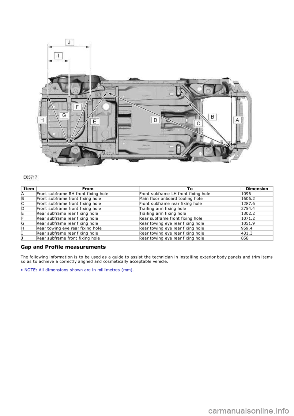
ItemFromT oDimension
AFront s ubframe RH front fixi ng hol eFront s ubframe LH front fi xi ng hole1096BFront s ubframe front fixing holeMain fl oor onboard t ool ing hol e1606.2
CFront s ubframe front fixing holeFront s ubframe rear fi xing hole1287.6
DFront s ubframe front fixing holeTrai ling arm fi xi ng hole2754.4ERear s ubframe rear fixing holeTrai ling arm fi xi ng hole1302.2
FRear s ubframe rear fixing holeRear subframe front fixing hole1071.2
GRear s ubframe rear fixing holeRear towing eye rear fi xi ng hole1051.9HRear t owing eye rear fixing hol eRear towing eye rear fi xi ng hole959.4
IRear s ubframe rear fixing holeRear towing eye rear fi xi ng hole431.3
JRear s ubframe front fi xi ng holeRear towing eye rear fi xi ng hole858
Gap and Profile measurements
The fol lowing informati on is to be used as a guide t o as si s t the t echni ci an in ins tall ing ext erior body panel s and trim i temss o as t o achi eve a correct ly al igned and cos met ically acceptable vehicle.
• NOTE: All di mens i ons shown are in mil li metres (mm).
Page 2724 of 3229

Contents
4
L
Climate control
AIR VENTS ................................................... 101
MANUAL CLIMATE CONTROL ...................... 102
AUTOMATIC CLIMATE CONTROL ................. 103
HEATED WINDOWS AND MIRRORS ............ 104
AUXILIARY HEATER ..................................... 104
ELECTRIC SUNROOF .................................... 105
Convenience features
SUN VISORS ................................................ 107
CLOCK .......................................................... 107
CIGAR LIGHTER ........................................... 109
ASHTRAY ..................................................... 109
AUXILIARY POWER SOCKETS ..................... 110
CUP HOLDERS ............................................. 111
STORAGE COMPARTMENTS ........................ 112
Starting the engine
GENERAL INFORMATION ............................. 113
STARTING A PETROL ENGINE ..................... 114
STARTING A DIESEL ENGINE ....................... 115
DIESEL PARTICULATE FILTER (DPF) ........... 116
Transmission
MANUAL TRANSMISSION ............................ 118
AUTOMATIC TRANSMISSION ...................... 118
TECHNICAL SPECIFICATIONS ...................... 122
Brakes
PRINCIPLE OF OPERATION .......................... 123
HINTS ON DRIVING WITH ABS .................... 123
PARKING BRAKE .......................................... 124
Parking aid
PRINCIPLE OF OPERATION .......................... 126
USING THE PARKING AID ............................ 127
Driving hints
GENERAL DRIVING POINTS ......................... 128
REDUCED ENGINE PERFORMANCE ............. 128
RUNNING-IN ................................................ 128
ECONOMICAL DRIVING ................................ 129
Cruise control
PRINCIPLE OF OPERATION .......................... 130
USING CRUISE CONTROL ............................ 130
Terrain response
PRINCIPLE OF OPERATION .......................... 132
USING TERRAIN RESPONSE ........................ 132
Hill descent control (HDC)
PRINCIPLE OF OPERATION .......................... 136
USING HDC ................................................... 137
Traction control
USING TRACTION CONTROL ........................ 139
Stability control
PRINCIPLE OF OPERATION .......................... 140
USING STABILITY CONTROL ........................ 141
Fuel and refuelling
SAFETY PRECAUTIONS................................. 142
FUEL QUALITY .............................................. 142
RUNNING OUT OF FUEL................................ 144
FUEL CUT-OFF............................................... 144
FUEL FILLER FLAP ........................................ 144
REFUELLING ................................................. 145
TECHNICAL SPECIFICATIONS ....................... 146
Load carrying
GENERAL INFORMATION.............................. 147
LUGGAGE ANCHOR POINTS ......................... 148
LUGGAGE COVERS ....................................... 149
Towing
TOWING A TRAILER...................................... 150
LEVELLING.................................................... 151
ESSENTIAL TOWING CHECKS ...................... 151
RECOMMENDED TOWING WEIGHTS ............ 152
TOW BAR ...................................................... 153
Vehicle care
CLEANING THE ALLOY WHEELS................... 154
CLEANING THE EXTERIOR ............................ 154
CLEANING THE INTERIOR ............................ 155
REPAIRING MINOR PAINT DAMAGE ............ 156
Maintenance
GENERAL INFORMATION.............................. 157
OPENING AND CLOSING THE BONNET......... 160
ENGINE COMPARTMENT OVERVIEW ........... 161
ENGINE OIL CHECK....................................... 162
Page 2725 of 3229

Contents
5
R
ENGINE COOLANT CHECK ............................ 163
BRAKE AND CLUTCH FLUID CHECK ............. 165
POWER STEERING FLUID CHECK ................ 166
WASHER FLUID CHECK ................................ 167
TECHNICAL SPECIFICATIONS ...................... 169
Vehicle battery
BATTERY WARNING SYMBOLS ................... 171
BATTERY CARE ............................................ 171
USING BOOSTER CABLES ............................ 173
CHARGING THE VE HICLE BATTERY ............. 174
CHANGING THE VE HICLE BATTERY ............. 174
Wheels and tyres
GENERAL INFORMATION ............................. 176
TYRE CARE ................................................... 177
USING WINTER TYRES................................. 183
CHANGING A ROAD WHEEL ......................... 183
TYRE REPAIR KIT ......................................... 187
USING SNOW CHAINS.................................. 192
TYRE GLOSSARY.......................................... 193
TECHNICAL SPECIFICATIONS ...................... 194
Fuses
FUSE BOX LOCATIONS ................................. 195
CHANGING A FUSE ....................................... 195
FUSE SPECIFICATION CHART....................... 196
Emergency equipment
HAZARD WARNING FLASHERS .................... 204
WARNING TRIANGLE ................................... 204
Status after a collision
DRIVING AFTER A COLLISION...................... 205
INSPECTING SAFETY SYSTEM COMPONENTS ...
206
Vehicle recovery
TOWING POINTS .......................................... 207
LASHING POINTS ......................................... 208
TRANSPORTING THE VEHICLE..................... 208
TOWING THE VEHICLE ON FOUR WHEELS .. 208
Vehicle identification
VEHICLE IDENTIFICATION PLATE................. 210
VEHICLE IDENTIFI CATION NUMBER (VIN) ... 210
VEHICLE BUILD DATE PLATE ....................... 210
Technical specifications
ENGINE SPECIFICATIONS ............................ 211
WEIGHTS...................................................... 212
DIMENSIONS................................................ 213
Type approval
Declarations of conformity ........................... 215
Audio introduction
RADIO RECEPTION....................................... 218
Audio unit overview
AUDIO UNIT OVERVIEW............................... 219
Audio unit operation
ON OR OFF CONTROL .................................. 223
VOLUME CONTROL ...................................... 223
AUDIO CONTROL ......................................... 223
WAVEBAND BUTTON ................................... 224
AUTOSTORE CONTROL ................................ 225
STATION PRESET BUTTONS ........................ 226
TRAFFIC INFORMATION CONTROL .............. 226
Audio unit menus
RADIO DATA SYSTEM (RDS) ....................... 228
REGIONAL MODE (REG) .............................. 228
ENHANCED OTHER NETWORK (RDS-EON).. 229
ALTERNATIVE FREQUENCIES ...................... 229
NEWS BROADCASTS ................................... 230
PRIORITY PROGRAMME TYPE (PTY) .......... 231
RESETTING THE AUDIO UNIT ...................... 233
Digital audio broadcasting
GENERAL INFORMATION ............................. 234
AUDIO CONTROLS ....................................... 235
DISPLAY OPTIONS ....................................... 236
CHANNEL AUTOMATIC TUNING................... 236
CHANNEL OPTIONS ..................................... 236
PRESET BUTTONS ....................................... 238
SETTINGS..................................................... 240
Compact disc player
LOADING COMPACT DISCS ......................... 245
EJECTING COMPACT DISCS ........................ 246
EJECTING MULTIPLE CO MPACT DISCS....... 246
COMPACT DISC SELECTION ........................ 246
COMPACT DISC PLAYBACK ......................... 246
Page 2741 of 3229
21
Quick start
R
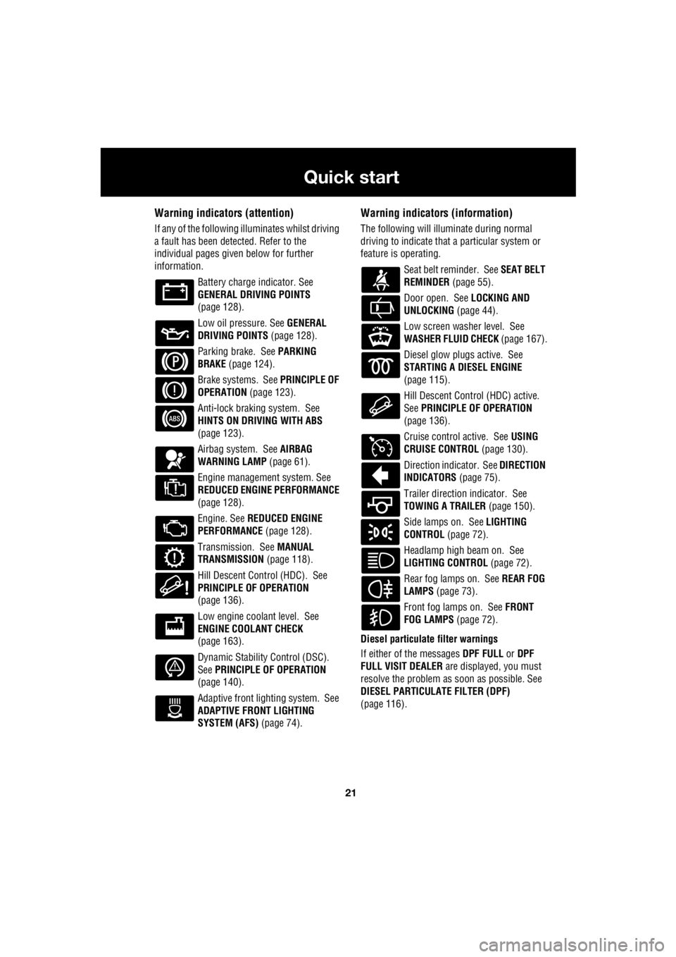
Warning indicators (attention)
If any of the following illuminates whilst driving
a fault has been detected. Refer to the
individual pages give n below for further
information.
Battery charge indicator. See
GENERAL DRIVING POINTS
(page 128).
Low oil pressure. See GENERAL
DRIVING POINTS (page 128).
Parking brake. See PARKING
BRAKE (page 124).
Brake systems. See PRINCIPLE OF
OPERATION (page 123).
Anti-lock braking system. See
HINTS ON DRIVING WITH ABS
(page 123).
Airbag system. See AIRBAG
WARNING LAMP (page 61).
Engine management system. See
REDUCED ENGINE PERFORMANCE
(page 128).
Engine. See REDUCED ENGINE
PERFORMANCE (page 128).
Transmission. See MANUAL
TRANSMISSION (page 118).
Hill Descent Control (HDC). See
PRINCIPLE OF OPERATION
(page 136).
Low engine coolant level. See
ENGINE COOLANT CHECK
(page 163).
Dynamic Stability Control (DSC).
See PRINCIPLE OF OPERATION
(page 140).
Adaptive front lighting system. See
ADAPTIVE FRONT LIGHTING
SYSTEM (AFS) (page 74).
Warning indicators (information)
The following will illuminate during normal
driving to indicate that a particular system or
feature is operating.
Seat belt reminder. See SEAT BELT
REMINDER (page 55).
Door open. See LOCKING AND
UNLOCKING (page 44).
Low screen washer level. See
WASHER FLUID CHECK (page 167).
Diesel glow plugs active. See
STARTING A DIESEL ENGINE
(page 115).
Hill Descent Control (HDC) active.
See PRINCIPLE OF OPERATION
(page 136).
Cruise control active. See USING
CRUISE CONTROL (page 130).
Direction indicator. See DIRECTION
INDICATORS (page 75).
Trailer direction indicator. See
TOWING A TRAILER (page 150).
Side lamps on. See LIGHTING
CONTROL (page 72).
Headlamp high beam on. See
LIGHTING CONTROL (page 72).
Rear fog lamps on. See REAR FOG
LAMPS (page 73).
Front fog lamps on. See FRONT
FOG LAMPS (page 72).
Diesel particulate filter warnings
If either of the messages DPF FULL or DPF
FULL VISIT DEALER are displayed, you must
resolve the problem as soon as possible. See
DIESEL PARTICULATE FILTER (DPF)
(page 116).
Page 2840 of 3229
Transmission
120
L
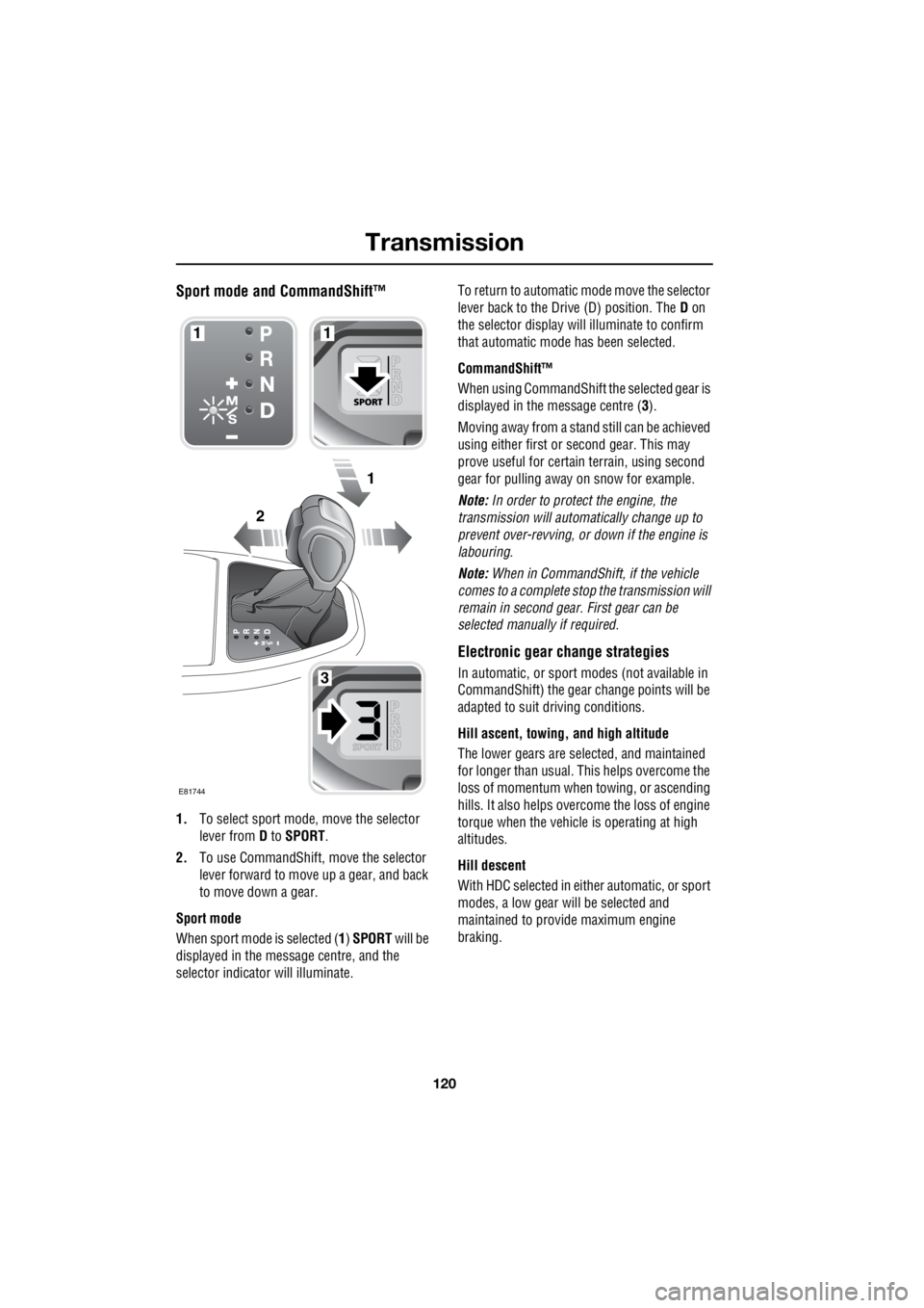
Sport mode and CommandShift™
1. To select sport mode, move the selector
lever from D to SPORT .
2. To use CommandShift, move the selector
lever forward to move up a gear, and back
to move down a gear.
Sport mode
When sport mode is selected ( 1) SPORT will be
displayed in the message centre, and the
selector indicator will illuminate. To return to automatic m
ode move the selector
lever back to the Drive (D) position. The D on
the selector display will illuminate to confirm
that automatic mode has been selected.
CommandShift™
When using CommandShift th e selected gear is
displayed in the message centre ( 3).
Moving away from a stand still can be achieved
using either first or second gear. This may
prove useful for certai n terrain, using second
gear for pulling away on snow for example.
Note: In order to protect the engine, the
transmission will automatically change up to
prevent over-revving, or down if the engine is
labouring.
Note: When in CommandShift, if the vehicle
comes to a complete stop the transmission will
remain in second gear. First gear can be
selected manually if required.
Electronic gear change strategies
In automatic, or sport modes (not available in
CommandShift) the gear change points will be
adapted to suit driving conditions.
Hill ascent, towing, and high altitude
The lower gears are selected, and maintained
for longer than usual. This helps overcome the
loss of momentum when towing, or ascending
hills. It also helps over come the loss of engine
torque when the vehicle is operating at high
altitudes.
Hill descent
With HDC selected in either automatic, or sport
modes, a low gear will be selected and
maintained to provide maximum engine
braking.
2
1
1
3
1
E81744
Page 2847 of 3229
127
Parking aid
R
USING THE PARKING AID
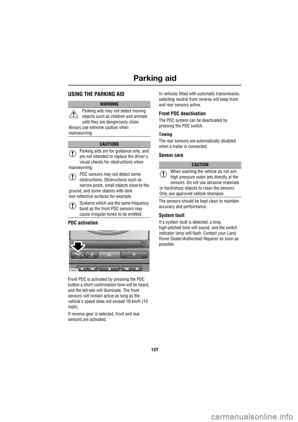
PDC activation
Front PDC is activate d by pressing the PDC
button a short confirmation tone will be heard,
and the tell-tale will illuminate. The front
sensors will remain active as long as the
vehicle's speed does not exceed 16 km/h (10
mph).
If reverse gear is selected, front and rear
sensors are activated. In vehicles fitted with automatic transmission,
selecting neutral from re verse will keep front
and rear sensors active.
Front PDC deactivation
The PDC system can be deactivated by
pressing the PDC switch.
Towing
The rear sensors are au tomatically disabled
when a trailer is connected.
Sensor care
The sensors should be ke pt clean to maintain
accuracy and performance.
System fault
If a system fault is detected, a long
high-pitched tone will sound, and the switch
indicator lamp will fl ash. Contact your Land
Rover Dealer/Authorised Repairer as soon as
possible.
WARNING
Parking aids may not detect moving
objects such as children and animals
until they are dangerously close.
Always use extreme caution when
manoeuvring.
CAUTIONS
Parking aids are for guidance only, and
are not intended to replace the driver's
visual checks for obstructions when
manoeuvring.
PDC sensors may not detect some
obstructions. Obstru ctions such as
narrow posts, small objects close to the
ground, and some objects with dark
non-reflective surfaces for example.
Systems which use the same frequency
band as the front PDC sensors may
cause irregular tones to be emitted.
E79872
CAUTION
When washing the vehicle do not aim
high pressure water je ts directly at the
sensors. Do not use abrasive materials
or hard/sharp objects to clean the sensors.
Only use approved vehicle shampoo.
Page 2870 of 3229
Towing
150
L
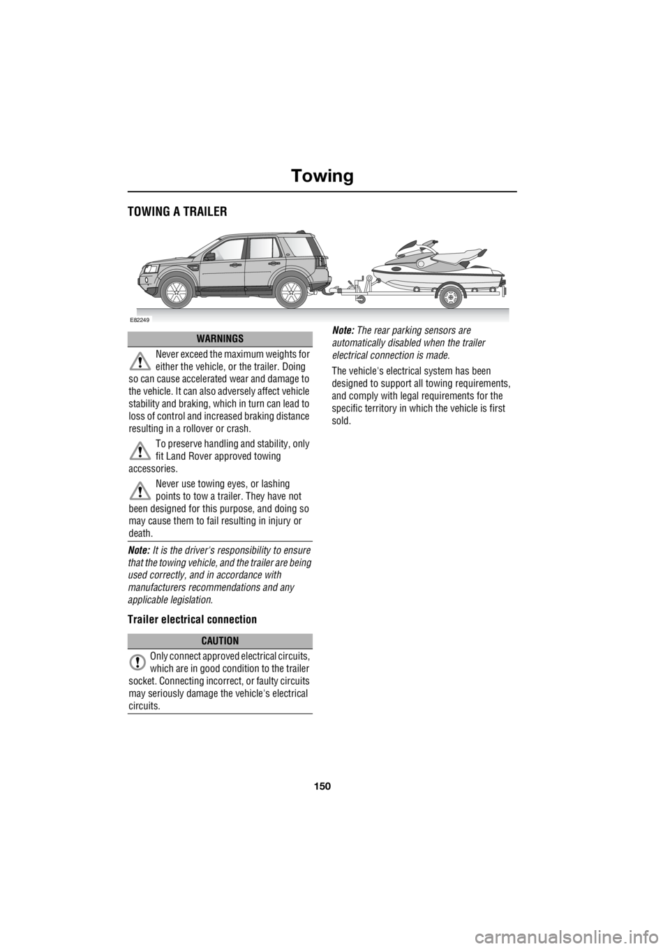
TowingTOWING A TRAILER
Note: It is the driver's re sponsibility to ensure
that the towing vehicle, and the trailer are being
used correctly, and in accordance with
manufacturers recomm endations and any
applicable legislation.
Trailer electrical connection
Note: The rear parking sensors are
automatically disabled when the trailer
electrical conne ction is made.
The vehicle's electrical system has been
designed to support all towing requirements,
and comply with legal requirements for the
specific territory in which the vehicle is first
sold.
E82249
WARNINGS
Never exceed the maximum weights for
either the vehicle, or the trailer. Doing
so can cause accelerate d wear and damage to
the vehicle. It can also adversely affect vehicle
stability and braking, which in turn can lead to
loss of control and incr eased braking distance
resulting in a rollover or crash.
To preserve handling and stability, only
fit Land Rover approved towing
accessories.
Never use towing eyes, or lashing
points to tow a trailer. They have not
been designed for this purpose, and doing so
may cause them to fail resulting in injury or
death.
CAUTION
Only connect approved electrical circuits,
which are in good condition to the trailer
socket. Connecting incorrect , or faulty circuits
may seriously damage the vehicle's electrical
circuits.
Page 2871 of 3229
151
Towing
R
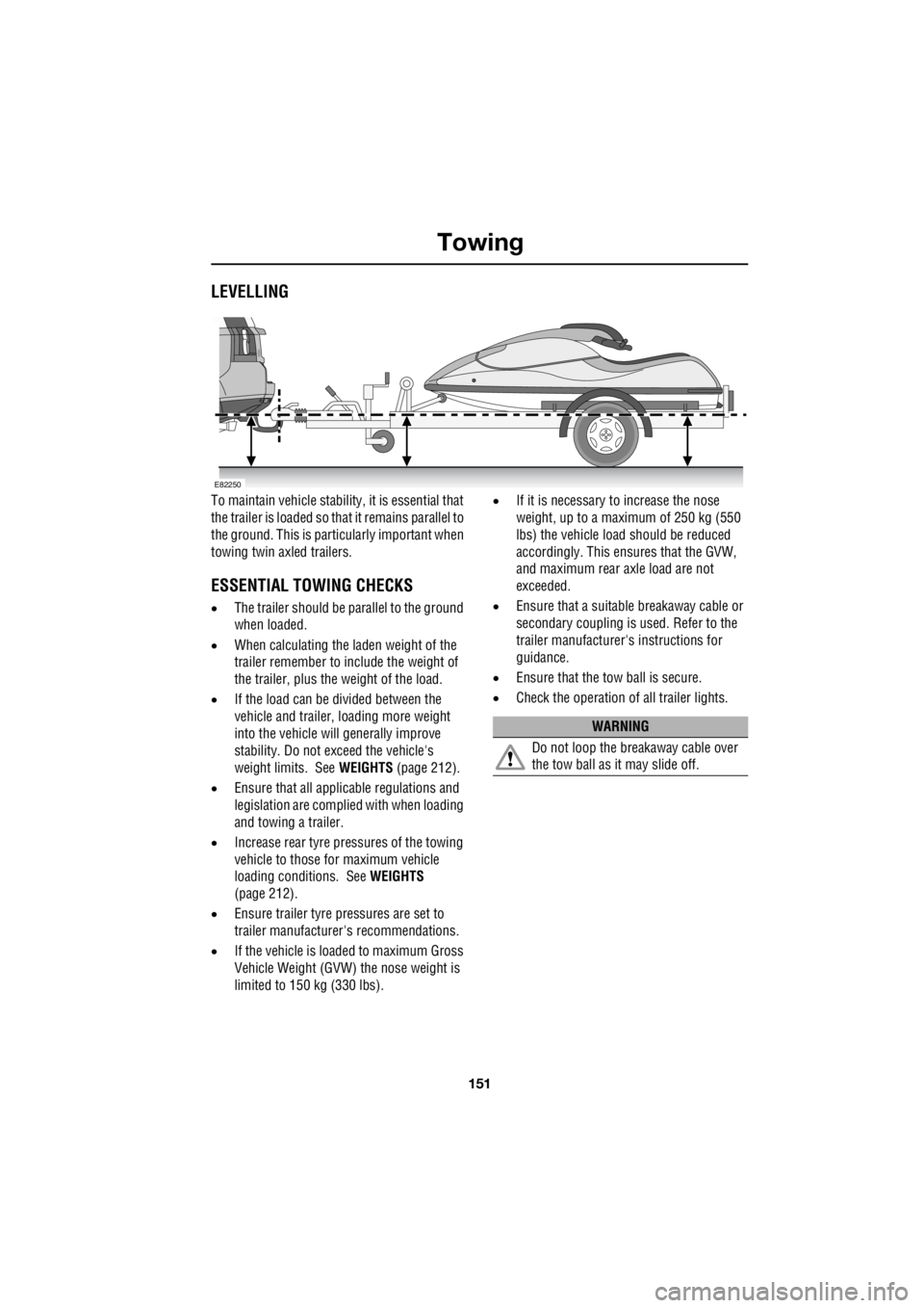
LEVELLING
To maintain vehicle stability, it is essential that
the trailer is loaded so that it remains parallel to
the ground. This is partic ularly important when
towing twin axled trailers.
ESSENTIAL TOWING CHECKS
• The trailer should be pa rallel to the ground
when loaded.
• When calculating the laden weight of the
trailer remember to include the weight of
the trailer, plus the weight of the load.
• If the load can be divided between the
vehicle and trailer, loading more weight
into the vehicle will generally improve
stability. Do not exceed the vehicle's
weight limits. See WEIGHTS (page 212).
• Ensure that all applic able regulations and
legislation are complied with when loading
and towing a trailer.
• Increase rear tyre pressures of the towing
vehicle to those for maximum vehicle
loading conditions. See WEIGHTS
(page 212).
• Ensure trailer tyre pressures are set to
trailer manufacture r's recommendations.
• If the vehicle is loaded to maximum Gross
Vehicle Weight (GVW) the nose weight is
limited to 150 kg (330 lbs). •
If it is necessary to increase the nose
weight, up to a maximum of 250 kg (550
lbs) the vehicle load should be reduced
accordingly. This ensures that the GVW,
and maximum rear axle load are not
exceeded.
• Ensure that a suitable breakaway cable or
secondary coupling is used. Refer to the
trailer manufacturer' s instructions for
guidance.
• Ensure that the tow ball is secure.
• Check the operation of all trailer lights.
E82250
WARNING
Do not loop the breakaway cable over
the tow ball as it may slide off.