2006 LAND ROVER FRELANDER 2 check engine
[x] Cancel search: check enginePage 14 of 3229
Publi s hed: 11-May-2011
General Information - Standard Workshop Practices
Des cript ion and Operat ion
Vehicle in Workshop
W hen working on a vehicl e in the workshop al ways make sure t hat :
W here practi cable, t he parking brake is appli ed and t he wheel s are securely chocked to prevent t he vehi cl e movingforwards or backwards .W henever pos si ble, t he ignit ion key i s removed before any work is carried out on t he vehi cle.If the engine i s t o be run, t here i s adequat e vent il ati on, or an extract ion hos e i s us ed to remove exhaus t fumes.There i s adequat e room to rais e the vehicle and remove t he wheel s , if neces s ary.Fender covers are al ways ins tal led i f any work i s to be carri ed out in t he engine compart ment.W here practi cable, t he batt ery i s dis connected if worki ng on the engi ne, underneath t he vehicle, or if t he vehi cl e i srai sed.
• CAUTIO NS:
Prior to dis connect ing the bat tery, refer to the El ect ri cal Secti on of this manual - Bat tery dis connect ion/connect ion.For addit ional informat ion, refer t o: Specificati ons (414-01 Bat t ery, Mount ing and Cables , Speci ficat ions).
W hen el ect ri c arc wel ding on a vehi cl e, al ways dis connect t he generator wi ri ng to prevent t he pos si bili ty of a s urgeof current caus i ng damage to the i nternal component s of the generat or.
If us i ng welding equipment on t he vehicle, a s uit abl e fire exti nguis her is readily avail able.
Battery - General
• CAUTIO NS:
Prior to carrying out any procedures which i nvol ve dis connect ing/ or connecti ng the bat tery, refer t o t he ElectricalSect ion of t his manual - Batt ery di sconnect ion/connect ion.For addit ional informat ion, refer t o: Specificati ons (414-01 Bat t ery, Mount ing and Cables , Speci ficat ions).
A di s charged bat tery condit ion may have been caus ed by an electrical short ci rcuit . If t his condit ion exis t s there wil lbe an apparentl y li ve circuit on the vehicle even when al l normal circuit s are s wit ched off. This can cause arcing when t hejumper cables are connect ed.
W hi le it i s not recommended that the vehicl e is jump s t art ed, i t is recognized t hat thi s may occas ionall y be t he onl ypracti cal way t o mobi lize a vehi cl e. Prior t o at tempt ing a jump s t art , reference must be made to the El ect ri cal Secti on oft hi s manual - Jump St art ing.
Followi ng jump s tart ing of a dis abl ed vehi cle, the di s charged bat tery mus t be checked for s erviceabili ty and recharged offt he vehi cl e as s oon as poss ibl e t o avoi d permanent damage.
Do not rel y on t he generator t o res t ore a di s charged bat tery. For a generat or t o recharge a batt ery, it woul d take i n exces sof eight hours cont inuous dri vi ng wi th no addi ti onal loads placed on t he batt ery.
Always make s ure that t he jumper cabl es are adequate for the tas k.Always make s ure that t he s lave batt ery i s of the same vol tage as t he vehicle bat tery. The bat teries mus t beconnected i n paral lel.Always make s ure that s wit chabl e electric circui ts are s wi tched off before connecti ng jumper cabl es. This reducest he ri sk of arci ng occurring when the final connecti on is made.
Towing the Vehicle
W ARNING: W hen t owing i s neces sary, reference mus t be made to the Jacki ng, Lift ing and Towing Secti on of thi sManual .
W hen t he vehicle i s being t owed dock the remote cont rol and s wit ch on the ignit ion. (s t eering l ock releas ed and warni ngli ght s i ll uminated). Onl y t hen wil l the s t eering, turn s ignal lamps , horn and s t op lamps be operat ional. Fail ure t o followt hes e i nst ructi ons may res ult in pers onal injury. It mus t be noted that wit h t he engine not running, t he power s t eering andbrake boost er wil l be inoperat ive t herefore, great er effort wil l be needed t o s t eer t he vehicle and apply the brakes .
General Installation Instructions
Component removal
W henever pos si ble, clean component s and the surroundi ng area before removal .
Blank off openings expos ed by component removal .Followi ng dis connecti on, s eal fuel, oil or hydrauli c li nes i mmediat ely us ing sui table bl anki ng plugs or caps .Seal open ends of expos ed oil ways us i ng sui table tapered hardwood pl ugs or cons pi cuous pl as t ic pl ugs .Immediat el y a component i s removed, place it i n a sui table contai ner; us e a s eparate cont ai ner for each componentand it s as s ociat ed part s .
Page 21 of 3229
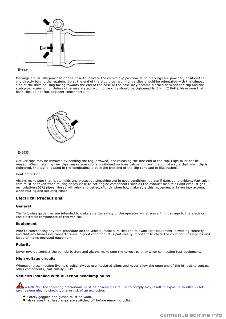
Marki ngs are us ual ly provi ded on t he hos e t o i ndi cat e t he correct cli p posi ti on. If no markings are provi ded, pos it ion t heclip direct ly behind t he ret aini ng li p at the end of t he s tub pi pe. W orm dri ve clips s hould be orient at ed wi th the crimpeds ide of t he dri ve hous ing facing t owards t he end of the hos e or t he hos e may become pi nched bet ween the cli p and t hes tub pi pe ret aining l ip. Unles s ot herwis e s t ated, worm dri ve cl ips s hould be ti ght ened to 3 Nm (2 lb-ft). Make s ure t hathose cl ips do not foul adjacent components .
Oeti ker cl ips may be removed by bendi ng the tag (arrowed) and releas ing t he free end of t he cl ip. Cli ps mus t not bereus ed. W hen ins t al li ng new cli ps , make s ure cl ip is pos it ioned on hose before ti ghtening and make s ure that when cli p ist ightened, the t ag is locat ed i n t he longit udi nal s lot i n t he free end of the cl ip (arrowed in il lus trat ion).
Heat protect ion
Always make s ure that heats hields and protecti ve s heat hing are in good condit ion; replace i f damage i s evident. Part icularcare mus t be t aken when rout ing hos es cl ose to hot engine component s s uch as the exhaust mani fol ds and exhaust gasrecircul ati on (EGR) pipes . Hoses will relax and defl ect s l ightl y when hot, make s ure thi s movement is t aken into accountwhen rout ing and s ecuring hos es .
Electrical Precautions
General
The fol lowing gui del ines are int ended t o make s ure the safet y of t he operator whil s t prevent ing damage t o t he electricaland electroni c component s of this vehi cl e.
Equipment
Pri or to commencing any t est procedure on the vehicl e, make sure t hat t he rel evant test equipment i s working correctl yand t hat any harnes s or connectors are i n good condi ti on. It is parti cul arly import ant to check t he condit ion of al l pl ugs andleads of mains operat ed equipment.
Polarity
Never revers e connect the vehicle bat tery and always make s ure the correct pol arit y when connect ing t est equipment .
High voltage circuits
W henever di sconnect ing l ive ht circuit s , always us e ins ulat ed pliers and never all ow t he open end of the ht l ead to cont actother component s, part icularly ECU's .
Vehicles installed with Bi-Xenon headlamp bulbs
W ARNING: The foll owing precauti ons mus t be obs erved as fail ure t o comply may res ult i n expos ure to ul tra-vi ol etrays , s evere electric s hock, burns or ris k of an expl osi on.
Safet y goggl es and gl oves must be worn.Make s ure t hat headlamps are s wi tched off before removi ng bul bs.
Page 39 of 3229
Health Protection Precautions
Avoi d prol onged and repeat ed cont act wit h oil s, parti cularly us ed engine oi ls .W ear prot ect ive clot hing, including i mpervious gl oves where practi cable.Do not put oily rags i nt o pocket s .Avoi d contami nat ing cl ot hes, parti cularly underpants , wi th oi l.Heavi ly s oil ed clot hi ng and oil -i mpregnated foot wear s hould not be worn. Overall s mus t be cleaned regularly.First Ai d t reatment s hould be obt ained i mmediat el y for open cuts and wounds .Us e barrier creams , appl yi ng t hem before each work peri od, t o help the removal of oil from t he s ki n.W as h wi th soap and wat er to make s ure al l oi l is removed (s kin cl eans ers and nail brushes wi ll help). Preparati onscont aining lanol ine replace the nat ural s ki n oil s which have been removed.Do not us e gasol ine (pet rol ), keros ene (paraffin), di esel fuel (gas oi l), thi nners or s ol vent s for cleaning skin.If skin dis orders develop, obtain medical advice wi thout delay.W here practi cable, degreas e component s pri or t o handling.W here there is a ri s k of eye cont act , eye protecti on s houl d be worn, for exampl e chemical goggles or face s hiel ds ;in addi ti on an eye was h facil it y s houl d be provided.
Environmental Precautions
This s ecti on provides general informati on which can help t o reduce t he environment al i mpact s from the act ivit ies carriedout in workshops .
Emis s ions t o air
Many of the act ivit ies t hat are carried out i n works hops emit gas es and fumes whi ch can contribut e to global warmi ng,depl eti on of the ozone layer and/or the format ion of phot ochemical s mog at ground level. By cons ideri ng how t he works hopact ivi ti es are carried out , thes e gases and fumes can be mi nimi s ed, t hus reduci ng t he impact on t he envi ronment.
Exhaus t fumes
Runni ng car engines i s an es sent ial part of works hop act ivi ti es and exhaust fumes need t o be venti lated to at mos phere.However, the amount of t ime engi nes are runni ng and the pos it ion of t he vehi cle s hould be carefully cons idered at al lt imes , to reduce the releas e of poi s onous gas es and mini mis e t he i nconveni ence t o peopl e l iving nearby.
Solvent s
Some of t he cl eani ng agent s us ed are sol vent based and wil l evaporate rapidl y to atmos phere i f used carel ess l y, or i fcont ainers are l eft unseal ed. Al l contai ners mus t be firmly cl os ed when not requi red and s olvent should be used sparingly.W herever poss i bl e, sol vent s havi ng a l ow t oxi ci ty and flammabi li ty should be sel ect ed. Al ways foll ow t he ins t ructi onss uppl ied by t he s olvent manufact urer. Si mil arl y, many pai nt s are s olvent bas ed and the s pray s houl d be us ed in such away as t o reduce emi ss i ons t o a mini mum.
Refrigerant
It is i ll egal t o rel eas e any refrigerant int o t he atmos phere. Dis charge and repl acement of thes e mat eri al s from aircondi ti oni ng uni ts should onl y be carried out us ing t he appropri at e equipment .
Dis charges to water
Mos t works hops wi ll have t wo s ys t ems for di schargi ng wast e wat er - st orm drai ns and foul drains . Storm drains s houl d onlyreceive clean wat er i.e. rainwat er. Foul drai ns wil l accept many of the normal was t e wat er i .e. was hing wat er, detergent sand domest ic type was te BUT NOT oi l, petrol, s olvent , acids , hydraul ic fluid, anti freeze and si mil ar fl ui ds. If in doubt ,always cons ult the l ocal authori ty or wat er company.
Spill ages
Every precauti on mus t be taken t o prevent s pi ll age of oi l, fuel , sol vent s etc., reachi ng the drains . All handl ing of s uchmat erial s mus t take pl ace wel l away from drai ns and preferably i n an area wit h a s uit able contai ni ng wall t o preventdis charge int o drai ns or watercours es . If a spi llage occurs , it mus t be s oaked up immedi ately us i ng a s pil l ki t whereprovided.
Checkli s t
Spillage prevention:
Store li quids in a s ecure area.
Make s ure t hat taps on l iquid cont ai ners are s ecure and cannot be acci dent ally turned on.
Prot ect bulk st orage t anks from vandal is m by locki ng the val ves .
Trans fer li quids from one cont ai ner t o another i n an area away from open drai ns .
Ensure li ds are replaced s ecurel y on cont ainers .
Have s pi ll kit s availabl e near t o point s of s torage and liquid handl ing areas .
Spill Ki ts
Speci al mat eri als are avai lable to abs orb a number of di fferent subs tances. They can be in granular form, ready t o us e andare suppli ed in sui table cont ai ners . Dis posal of used spi ll absorbing mat eri al i s deal t wit h i n W as t e management .
Land contamination
Oil s , fuels and s olvents etc. can cont aminate any soi l wit h which t hey come int o cont act . Such materials MUST never bedis posed of by pouri ng on t o s oil and every precauti on mus t be t aken t o avoid s pil lage reaching s oil . W as te materials
Page 44 of 3229
Publi s hed: 11-May-2011
General Information - Road/Roller Testing
Des cript ion and Operat ion
Road or roll ing road t es t ing may be carri ed out for various reasons and a procedure det ail ing pre-t es t checks , throughengi ne s tarti ng and s topping, pre-driving checks , on-t es t checks to final checks on complet ion of t he tes t are given.
Unles s complete vehi cl e performance is bei ng checked, t he ful l road t est procedure need not be carried out . Ins tead, t hos eit ems part icularly relevant t o t he s yst em(s) bei ng checked can be ext racted.
Pre-Test Checks
W ARNING: If t he brake s yst em hydraul ic fluid level i s l ow, pedal travel i s exces si ve or a hydraulic leak is found, donot att empt to road t est t he vehicle unt il t he reas on for t he low fl ui d l evel, excess ive pedal travel or hydraulic leak isfound and rect ified.
It is s ugges t ed that pre-t es t and funct ional t es ts of t hose sys tems/circuit s whi ch affect t he safe and l egal operati ons oft he vehi cl e, s uch as brakes , light s and s teeri ng, should al ways be carri ed out before the road or roll ing road tes t .
Engi ne oil l evelEngi ne cool ant levelTires, for correct pres sure, compat ible types and tread patt erns , and wear wi thi n limi ts .There i s s ufficient fuel in the t ank to compl ete the t est .Check al l around the engine, t rans mis s ion and under the vehicle for oil , coolant , hydraul ic and fuel l eaks . Make anote of any apparent leaks and wipe off t he surrounding areas t o make it easi er to identi fy t he extent of the leakon complet ion of t he tes t.
Starting the Engine
• NOTE: On i nit ial dri ve away from cold and wit hi n t he fi rs t 1.5 km (1 mile), do not depress accelerat or pedal beyond halft ravel unt il t he vehi cl e has att ained a minimum s peed of 25 km/h (15 mil es /h). Never operat e at high engi ne speed or wi tht he accelerat or pedal at ful l travel whil st the engine i s cold.
With the ignition off, check:
The parking brake is appli ed.Automatic transmission: The s el ect or lever is i n 'P' - PARK.Manual transmission: The gear l ever i s in NEUTRAL.All i ns t rument gauges read zero.
With the ignition on, check:
Igni ti on cont roll ed warni ng li ght s come on.Engi ne t emperature gauge regis t ers a readi ng compat ibl e wi th t he engine t emperat ure.Fuel gauge regi st ers a reading appropriate to the fuel l evel i n t he tank.The operati on of the parki ng brake warning l ight and fl ui d l evel warni ng indicator light.
On Road Test Check:
CAUTION: At commencement of road tes ti ng, check the brake operati on while s ti ll travel li ng at low speed beforecont inuing wit h t he tes t. If t he brakes pul l to one si de, or appear to be ot herwi se fault y, do not cont inue wit h t he roadt es t unti l the fault has been found and rect ified.
The parking brake releas es completel y.Gear changing i s s mooth, and t here are no abnormal noi s es or vi brati ons from t he t rans mis s ion.The engi ne power out put is s ati s factory, accel erati on is smoot h and accel erator pedal operat ion is not s ti ff orheavy, and engi ne s peed ret urns t o idl e correctl y.There i s no exces s ive or abnormall y colored s moke from t he engi ne under normal driving, heavy l oad or overruncondi ti ons .Steering operat ion i s s moot h, accurat e, not exces s ively heavy or wit h exces s ive free pl ay or vibrat ion. Does not pul lt o one s ide and s elf centres smoot hly after corneri ng.All i ns t rument s regis t er the correct readi ngs and operate correctl y.Swit ches and controls operat e s moothl y and posi ti vel y, warning or i ndi cat or light s operate correctl y and thedirect ion i ndi cat or cont rol s elf cancels when the s t eering i s ret urned t o t he s traight ahead pos it ion.Heati ng and vent il at ion sys tems work correct ly and effect ively.Brakes operate efficientl y.
Brake Testing
Avoi d brake t es ti ng on busy roads where i t can caus e i nconveni ence or danger t o ot her road users.
CAUTION: Brake t es ti ng which i ncludes heavy brake appl icati ons should not be carri ed out wit h new brake pads /dis csunti l the component s have bedded-i n. New brake fri ct ion component s wi ll not reach ful l efficiency unt il t he beddi ng-inprocess is complet e. Not e t hat when new parking brake shoes or rear brake di scs have been ins t al led, it i s es sent ial thatt he 'beddi ng-in' procedure i s carri ed out.For addit ional informat ion, refer t o: Parking Brake Shoes Bedding-In (206-05 Parking Brake and Actuati on, GeneralProcedures).
Test t he brakes at s everal speeds wit hin the normal operat ing range usi ng both light and heavy pedal pres s ure. Note anyt endency to snat ch, pull or drag, and any undue del ay in appli cat ion or release.
Page 65 of 3229
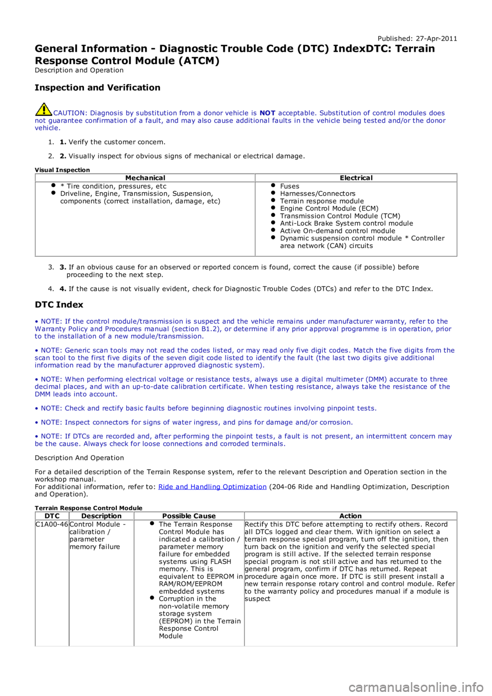
Publ is hed: 27-Apr-2011
General Information - Diagnostic Trouble Code (DTC) IndexDTC: Terrain
Response Control Module (ATCM)
Des cript ion and Operat ion
Inspection and Verification
CAUTION: Di agnos is by s ubs ti tut ion from a donor vehicle is NO T acceptabl e. Subs ti tut ion of cont rol modules doesnot guarant ee confirmat ion of a faul t, and may als o caus e addit ional fault s i n t he vehi cl e being t est ed and/or t he donorvehi cl e.
1. Verify t he cus t omer concern.1.
2. Vis ually ins pect for obvious s igns of mechani cal or electrical damage.2.
Visual InspectionMechanicalElectrical
* Ti re condit ion, pres sures, et cDriveline, Engine, Transmis s ion, Sus pensi on,component s (correct ins tall ati on, damage, etc)
Fus esHarness es /Connect orsTerrai n res pons e modul eEngi ne Cont rol Module (ECM)Transmis s ion Control Modul e (TCM)Ant i-Lock Brake Sys t em control modul eAct ive On-demand cont rol moduleDynami c s us pensi on cont rol module * Controllerarea network (CAN) ci rcuit s
3. If an obvious cause for an obs erved or report ed concern is found, correct t he caus e (if pos s ible) beforeproceeding t o t he next s t ep.3.
4. If t he caus e is not vis ually evi dent , check for Di agnos ti c Trouble Codes (DTCs) and refer t o t he DTC Index.4.
DTC Index
• NOTE: If the control modul e/t rans mis s ion i s s uspect and the vehicle remai ns under manufacturer warrant y, refer t o t heW arranty Pol icy and Procedures manual (s ect ion B1.2), or determine i f any pri or approval programme is in operat ion, pri ort o the ins tall ati on of a new module/transmis s ion.
• NOTE: Generic scan t ool s may not read the codes li st ed, or may read only fi ve digit codes . Mat ch the five di git s from t hes can tool to the firs t fi ve di git s of the seven digi t code l is ted to ident ify t he faul t (t he las t t wo digi ts gi ve addi ti onalinformat ion read by the manufact urer approved diagnos t ic s ys tem).
• NOTE: W hen performing el ect ri cal volt age or resi s tance tes t s, al ways us e a digit al mult imet er (DMM) accurate to threedeci mal places , and wi th an up-to-date cali brat ion cert ificate. W hen t es ti ng res is t ance, always take t he res i st ance of t heDMM leads int o account.
• NOTE: Check and recti fy bas ic faul ts before beginni ng diagnos t ic rout ines i nvol vi ng pinpoint t es t s.
• NOTE: Ins pect connect ors for s igns of water ingres s , and pins for damage and/or corros ion.
• NOTE: If DTCs are recorded and, aft er performi ng the pi npoi nt tes ts , a fault is not present , an int ermi tt ent concern maybe t he caus e. Always check for loose connect ions and corroded terminals .
Des cript ion And Operat ion
For a detail ed descripti on of the Terrain Respons e s ys t em, refer t o t he rel evant Descript ion and Operat ion secti on in theworks hop manual .For addit ional informat ion, refer t o: Ride and Handli ng Opti mizat ion (204-06 Ride and Handli ng Opt imi zat ion, Descripti onand Operat ion).
Terrain Response C ontrol ModuleDT CDescriptionPossible CauseAction
C1A00-46Control Module -cal ibrat ion /paramet ermemory fai lure
The Terrain Res ponseCont rol Modul e hasi ndi cat ed a cali brat ion /paramet er memoryfail ure for embeddeds ys tems us i ng FLASHmemory. Thi s i sequivalent t o EEPROM inRAM/ROM/EEPROMembedded s ys t emsCorrupti on in thenon-volat il e memorys t orage s yst em(EEPROM) in t he TerrainRes pons e Cont rolModule
Rect ify thi s DTC before att empti ng t o rect ify others . Recordal l DTCs logged and clear them. W it h ignit ion on sel ect aterrain res pons e s peci al program, t urn off the i gnit ion, thenturn back on the i gni ti on and veri fy t he s elected s peci alprogram is s t il l act ive. If t he s el ect ed t errai n res ponsespecial program is not s t il l act ive and has ret urned t o t hegeneral program, confirm i f DTC has ret urned. Repeatprocedure agai n once more. If DTC is st il l pres ent i nst all anew terrai n res pons e rotary cont rol and control modul e. Referto the warranty pol icy and procedures manual if a module issus pect
Page 66 of 3229
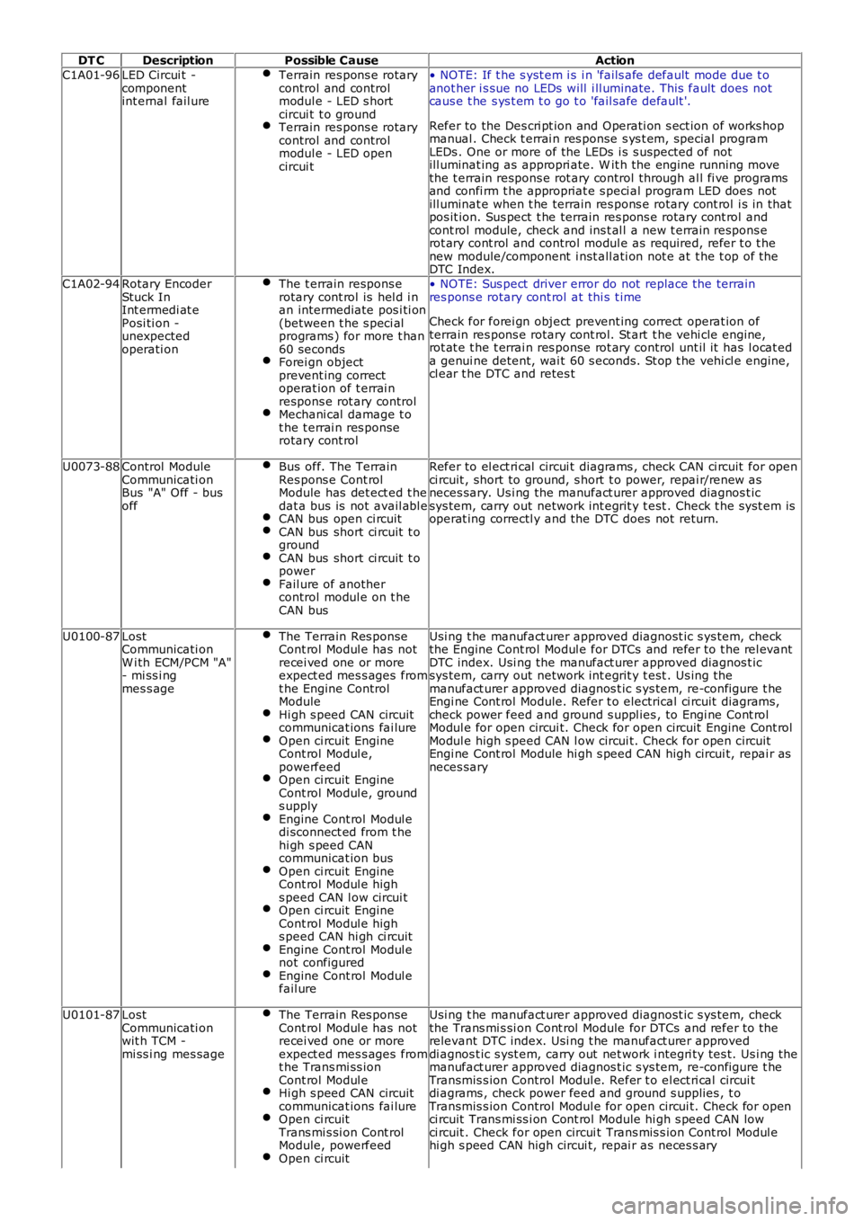
DT CDescriptionPossible CauseAction
C1A01-96LED Circui t -componentint ernal fail ure
Terrain res pons e rotarycontrol and controlmodul e - LED s hortcircui t t o groundTerrain res pons e rotarycontrol and controlmodul e - LED opencircui t
• NOTE: If t he s yst em i s i n 'fails afe default mode due t oanot her i s sue no LEDs will i ll uminate. This fault does notcaus e t he s ys t em t o go t o 'fail safe default '.
Refer to the Des cri pt ion and Operati on s ect ion of works hopmanual . Check t errai n res ponse s ys t em, special programLEDs . One or more of the LEDs i s s uspected of notill uminat ing as appropri ate. W it h the engi ne running movethe t errain respons e rot ary control through al l fi ve programsand confi rm t he appropriat e s peci al program LED does notill uminat e when t he terrain res pons e rotary cont rol i s in thatpos it ion. Sus pect t he terrain res pons e rotary cont rol andcont rol module, check and ins t al l a new t errain respons erot ary cont rol and control modul e as required, refer t o t henew module/component i nst all ati on not e at t he t op of theDTC Index.
C1A02-94Rotary EncoderStuck InInt ermedi at ePosi ti on -unexpectedoperati on
The t errain respons erotary cont rol is hel d i nan intermediate pos i ti on(between t he s peci alprograms ) for more t han60 secondsForei gn objectprevent ing correctoperat ion of t errai nrespons e rot ary controlMechani cal damage t ot he t errai n res ponserotary cont rol
• NOTE: Sus pect driver error do not replace the terrainres pons e rotary cont rol at thi s t ime
Check for forei gn object prevent ing correct operat ion ofterrain res pons e rotary cont rol. St art t he vehi cle engine,rot at e t he t errai n res ponse rot ary control unt il it has l ocat eda genui ne detent, wai t 60 s econds. St op t he vehi cl e engine,cl ear t he DTC and retes t
U0073-88Control ModuleCommunicati onBus "A" Off - busoff
Bus off. The TerrainRes pons e Cont rolModule has det ect ed t hedat a bus is not avail abl eCAN bus open ci rcuitCAN bus short ci rcuit t ogroundCAN bus short ci rcuit t opowerFail ure of anothercontrol modul e on t heCAN bus
Refer to el ect ri cal circui t diagrams , check CAN ci rcuit for openci rcuit , short to ground, s hort t o power, repai r/renew asneces sary. Us i ng the manufact urer approved diagnos t icsys tem, carry out network int egrit y t est . Check t he s yst em isoperat ing correctl y and the DTC does not return.
U0100-87LostCommunicati onW i th ECM/PCM "A"- mi ss i ngmes s age
The Terrain Res ponseCont rol Modul e has notrecei ved one or moreexpect ed mes s ages fromt he Engine ControlModuleHi gh s peed CAN circuitcommunicat ions fai lureOpen ci rcuit EngineCont rol Modul e,powerfeedOpen ci rcuit EngineCont rol Modul e, grounds upplyEngine Cont rol Modul edi sconnect ed from t hehi gh s peed CANcommunicat ion busOpen ci rcuit EngineCont rol Modul e highs peed CAN l ow circui tOpen ci rcuit EngineCont rol Modul e highs peed CAN hi gh ci rcuitEngine Cont rol Modul enot configuredEngine Cont rol Modul efail ure
Usi ng t he manufact urer approved diagnost ic s ys tem, checkthe Engine Cont rol Modul e for DTCs and refer t o t he rel evantDTC index. Usi ng the manufact urer approved diagnos t icsys tem, carry out network int egrit y t est . Us ing t hemanufact urer approved diagnos t ic s ys tem, re-configure t heEngi ne Cont rol Module. Refer t o electrical ci rcuit diagrams,check power feed and ground s uppl ies , to Engi ne Cont rolModul e for open circui t. Check for open circuit Engine Cont rolModul e high s peed CAN l ow circui t. Check for open circuitEngi ne Cont rol Module hi gh s peed CAN high circui t, repai r asneces sary
U0101-87LostCommunicati onwit h TCM -mi ss i ng mes sage
The Terrain Res ponseCont rol Modul e has notrecei ved one or moreexpect ed mes s ages fromt he Trans mi ss ionCont rol Modul eHi gh s peed CAN circuitcommunicat ions fai lureOpen ci rcuitTrans mi s si on Cont rolModule, powerfeedOpen ci rcuit
Usi ng t he manufact urer approved diagnost ic s ys tem, checkthe Trans mi s si on Cont rol Module for DTCs and refer to therelevant DTC index. Usi ng t he manufact urer approveddi agnos t ic s yst em, carry out net work i ntegri ty tes t. Us i ng themanufact urer approved diagnos t ic s ys tem, re-configure t heTransmis s ion Control Modul e. Refer t o el ect ri cal circui tdi agrams , check power feed and ground s upplies , t oTransmis s ion Control Modul e for open circui t. Check for openci rcuit Trans mi ss i on Cont rol Module hi gh s peed CAN lowci rcuit . Check for open circui t Trans mis s ion Cont rol Modul ehi gh s peed CAN high circui t, repai r as neces s ary
Page 68 of 3229
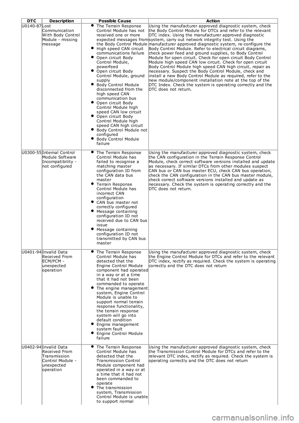
DT CDescriptionPossible CauseAction
U0140-87LostCommunicati onW i th Body Cont rolModule - mis s ingmes s age
The Terrain Res ponseCont rol Modul e has notrecei ved one or moreexpect ed mes s ages fromt he Body Control ModuleHi gh s peed CAN circuitcommunicat ions fai lureOpen ci rcuit BodyCont rol Modul e,powerfeedOpen ci rcuit BodyCont rol Modul e, grounds upplyBody Control Modul edi sconnect ed from t hehi gh s peed CANcommunicat ion busOpen ci rcuit BodyCont rol Modul e highs peed CAN l ow circui tOpen ci rcuit BodyCont rol Modul e highs peed CAN hi gh ci rcuitBody Control Modul e notconfi guredBody Control Modul efail ure
Usi ng t he manufact urer approved diagnost ic s ys tem, checkthe Body Control Modul e for DTCs and refer t o the relevantDTC index. Usi ng the manufact urer approved diagnos t icsys tem, carry out network int egrit y t est . Us ing t hemanufact urer approved diagnos t ic s ys tem, re-configure t heBody Cont rol Modul e. Refer to elect rical circui t diagrams ,check power feed and ground s uppl ies , to Body Cont rolModul e for open circui t. Check for open circuit Body ControlModul e high s peed CAN l ow circui t. Check for open circuitBody Cont rol Modul e high speed CAN hi gh circuit , repair asneces sary. Sus pect t he Body Cont rol Module, check andins tall a new Body Cont rol Module as required, refer to thenew module/component i nst all ati on not e at t he t op of theDTC Index. Check t he s ys t em i s operati ng correct ly and t heDTC does not return.
U0300-55Int ernal Cont rolModule Soft wareIncompati bili ty -not configured
The Terrain Res ponseCont rol Modul e hasfail ed to recogni se amat ching mas t erconfi gurati on ID fromt he CAN dat a busmas t erTerrain Res ponseCont rol Modul e hasi ncorrect CANconfi gurati onCAN bus mast er notcorrect ly confi guredMes s age cont ainingconfi gurati on ID notrecei ved due to CAN busi s sueMes s age cont ainingconfi gurati on ID nott rans mi tt ed by CAN busmas t er
Usi ng t he manufact urer approved diagnost ic s ys tem, checkthe CAN configurat ion i n the Terrai n Respons e ControlModul e, check correct s oftware vers ions i nst all ed and updat eas neces sary. If s imi lar DTCs from other modules s uspectCAN bus or CAN bus mas ter ECU, check CAN bus operat ion,check the CAN configurat ion i n t he CAN bus mas t er modul e,check correct s oft ware vers i ons ins tall ed and updat e asneces sary. Check the sys tem is operati ng correctl y and t heDTC does not return.
U0401-94Invali d Dat aRecei ved FromECM/PCM -unexpectedoperati on
The Terrain Res ponseCont rol Modul e hasdet ect ed that t heEngine Cont rol Modul ecomponent had operat edi n a way or at a ti met hat it had not beencommanded t o operateThe engine managements ys tem, Engine Cont rolModule is unable t os upport normal t errai nrespons e functi onal it y,t he t errai n res ponses ys tem wil l go int odefaul t condit ionEngine managements ys tem faultEngine Cont rol Modul efail ure
Usi ng t he manufact urer approved diagnost ic s ys tem, checkthe Engine Cont rol Modul e for DTCs and refer t o t he rel evantDTC index, recti fy as requi red. Check t he s yst em is operat ingcorrectl y and the DTC does not return
U0402-94Invali d Dat aRecei ved FromTrans mis s ionControl Module -unexpectedoperati on
The Terrain Res ponseCont rol Modul e hasdet ect ed that t heTrans mi s si on Cont rolModule component hadoperat ed in a way or ata ti me t hat it had notbeen commanded tooperat eThe t rans mi ss ions ys tem, Trans mi ss i onCont rol Modul e i s unabl et o s upport normal
Usi ng t he manufact urer approved diagnost ic s ys tem, checkthe Trans mi s si on Cont rol Module for DTCs and refer to therelevant DTC index, recti fy as requi red. Check the s ys tem isoperat ing correctl y and the DTC does not return
Page 72 of 3229
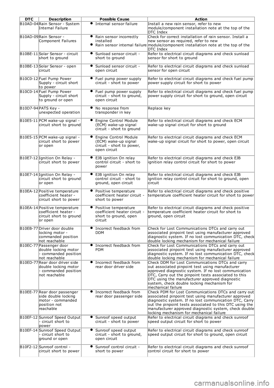
DT CDescriptionPossible CauseAction
B10AD-04Rain Sens or - Sys t emInt ernal FailureInternal s ens or fail ureIns t al l a new rain s ens or, refer to newmodule/component i nst all at ion not e at t he top of t heDTC Index
B10AD-09Rain Sens or -Component Fail uresRai n s ens or incorrect lyi nst all edRai n s ens or int ernal fail ure
Check for correct ins tal lati on of rai n s ens or. Ins tall anew s ens or as requi red, refer t o newmodule/component i nst all at ion not e at t he top of t heDTC Index
B10BE-11Solar Sens or - circui ts hort t o groundSunload s ens or circui t -s hort t o groundRefer to electrical ci rcuit diagrams and check s unl oads ens or for s hort t o ground
B10BE-13Solar Sens or - opencircui tSunload s ens or circui t -open circui tRefer to electrical ci rcuit diagrams and check s unl oads ens or for open circuit
B10C0-12Fuel Pump PowerSuppl y - circui t shortt o power
Fuel pump power supplyci rcuit - s hort t o powerRefer to electrical ci rcuit diagrams and check fuel pumppower s upply circui t for s hort t o power
B10C0-14Fuel Pump PowerSuppl y - circui t shortt o ground or open
Fuel pump power supplyci rcuit - s hort t o ground,open circui t
Refer to electrical ci rcuit diagrams and check fuel pumppower s upply circui t for s hort t o ground, open ci rcuit
B10D7-94PATS Key -unexpected operat ionNo res pons e fromt rans ponder i n keyRepl ace key
B10E5-11PCM wake-up si gnal -circui t short to groundEngine Cont rol Module(ECM) wake-up s ignalci rcuit - s hort t o ground
Refer to electrical ci rcuit diagrams and check ECMwake-up s ignal ci rcuit for short to ground
B10E5-15PCM wake-up si gnal -circui t short to poweror open
Engine Cont rol Module(ECM) wake-up s ignalci rcuit - s hort t o power,open circui t
Refer to electrical ci rcuit diagrams and check ECMwake-up s ignal ci rcuit for short to power, open circui t
B10E7-12Igni ti on On Relay -circui t short to powerEJB i gni ti on On relaycontrol ci rcuit - s hort t opower
Refer to electrical ci rcuit diagrams and check EJBignit ion relay control ci rcuit for s hort t o power
B10E7-14Igni ti on On Relay -circui t short to groundor open
EJB i gni ti on On relaycontrol ci rcuit - s hort t oground, open circuit
Refer to electrical ci rcuit diagrams and check EJBignit ion relay control ci rcuit for s hort t o ground, openci rcuit
B10EA-12Posi ti ve t emperaturecoeffi ci ent heat er -circui t short to power
Pos it ive t emperat urecoefficient heater circuit -s hort t o power
Refer to electrical ci rcuit diagrams and check posi ti vetemperat ure coeffici ent heater circui t for s hort t o power
B10EA-14Posi ti ve t emperaturecoeffi ci ent heat er -circui t short to groundor open
Pos it ive t emperat urecoefficient heater circuit -s hort t o ground, openci rcuit
Refer to electrical ci rcuit diagrams and check posi ti vetemperat ure coeffici ent heater circui t for s hort t oground, open circui t
B10EB-77Driver door doubl elocking mot or -commanded pos i ti onnot reachabl e
Incorrect feedback fromDDMCheck for Los t Communicati ons DTCs and carry outass ociated pi npoi nt tes t us ing manufacturer approveddiagnos t ic s ys tem. If no los t communicati on DTC, checkdoubl e locking mechani s m for mechanical fail ureB10EC-77Pass enger doordoubl e l ocking mot or- commanded pos i ti onnot reachabl e
Incorrect feedback fromPDMCheck for Los t Communicati ons DTCs and carry outass ociated pi npoi nt tes t us ing manufacturer approveddiagnos t ic s ys tem. If no los t communicati on DTC, checkdoubl e locking mechani s m for mechanical fail ureB10ED-77Rear door dri ver s i dedoubl e l ocking mot or- commanded pos i ti onnot reachabl e
Incorrect feedback fromrear door dri ver s i deCheck DDM for Los t Communicat ions DTCs and carryout as s oci ated pi npoi nt t es t usi ng manufacturerapproved di agnos ti c s yst em. If no los t communi cat ionDTC, Carry out t he pinpoint t est s as sociat ed t o thi sDTC us ing t he manufacturer approved diagnos ti cs ys t em, check doubl e locking mechanis m formechanical fai lure
B10EE-77Rear door pas sengers ide double l ocki ngmot or - commandedposi ti on notreachabl e
Incorrect feedback fromrear door pas senger si deCheck PDM for Lost Communi cat ions DTCs and carry outass ociated pi npoi nt tes t us ing manufacturer approveddiagnos t ic s ys tem. If no los t communicati on DTC, Carryout the pi npoint t es ts as s oci at ed t o t his DTC us ing themanufacturer approved diagnost ic sys tem, check doublelocki ng mechani sm for mechanical fail ureB10EF-12Sunroof Speed Out put- circui t short topower
Sunroof s peed out putci rcuit - s hort t o powerRefer to electrical ci rcuit diagrams and check s unroofs peed out put circui t for s hort t o power
B10EF-14Sunroof Speed Out put- circui t short toground or open
Sunroof s peed out putci rcuit - s hort t o ground,open circui t
Refer to electrical ci rcuit diagrams and check s unroofs peed out put circui t for s hort t o ground, open ci rcuit
B10F2-12Sunroof cont rol -circui t short to powerSunroof cont rol circui t -s hort t o powerRefer to electrical ci rcuit diagrams and check s unroofcont rol circuit for s hort to power