2006 LAND ROVER FRELANDER 2 check engine
[x] Cancel search: check enginePage 303 of 3229
1
2
DTC Index
• NOTE: If the control modul e or a component i s s us pect and the vehicle remains under manufacturer warrant y, refer t o theW arranty Pol icy and Procedures manual (s ect ion B1.2), or determine i f any pri or approval programme is in operat ion, pri ort o the ins tall ati on of a new module/component.
• NOTE: Generic scan t ool s may not read the codes li st ed, or may read only fi ve digit codes . Mat ch the five di git s from t hes can tool to the firs t fi ve di git s of the seven digi t code l is ted to ident ify t he faul t (t he las t t wo digi ts gi ve addi ti onalinformat ion read by the manufact urer approved diagnos t ic s ys tem).
• NOTE: W hen performing volt age or res is t ance t est s , always use a digi tal mult imeter (DMM) accurat e t o t hree deci malplaces, and wi th an up-t o-date cal ibrat ion cert ificate. W hen tes ti ng res is t ance al ways take t he res is t ance of t he DMMleads i nt o account .
• NOTE: Check and recti fy bas ic faul ts before beginni ng diagnos t ic rout ines i nvol vi ng pinpoint t es t s.
• NOTE: Ins pect connect ors for s igns of water ingres s , and pins for damage and/or corros ion.
• NOTE: If DTCs are recorded and, aft er performi ng the pi npoi nt tes ts , a fault is not present , an int ermi tt ent concern maybe t he caus e. Always check for loose connect ions and corroded terminals .
For a compl ete lis t of all Di agnos ti c Trouble Codes (DTCs) t hat could be logged on this vehicle, pleas e refer to Sect ion100-00.REFER t o: Di agnos t ic Trouble Code (DTC) Index - DTC: Rear Different ial Control Module (RDCM) (100-00 GeneralInformat ion, Des cript ion and Operat ion).
Pinpoint Tests
PINPOINT TEST A : EXCESSIVE DRIVELINE NOISE
T ESTCONDIT IONSDET AILS/RESULT S/ACT IONS
A1: CHECK NO ISE FRO M VEHICLE ON ROAD T EST
Road t est vehicle to det ermi ne load and s peed condi ti ons when noi se occurs .
As s es s t he nois e wi th different gears s elected.
Does t he noi s e occur in di fferent gears at t he s ame vehi cle s peed?YesINSTALL a new rear dri ve axle/di fferenti al as s embly.REFER t o: Di fferenti al Cas e (205-02 Rear Dri ve Axle/Di fferenti al, Removal and Ins tall ati on).RE-TEST t he s yst em for normal operati on.NoREFER t o: Engine (303-00 Engine Sys tem - General Informat ion, Diagnosi s and Test ing) /Di agnos ti cs (307-01 Aut omati c Trans mis s ion/Trans axle, Diagnos is and Tes ti ng).
Page 412 of 3229
1
1
1
1
2
3
4
5
6
7
1
1
Are the wheel bearings OK?YesGO to C6.NoINSTALL new wheel bearings as requi red.REFER to: Front W heel Beari ng (204-01 Front Sus pensi on, Removal and Ins t al lat ion).TEST t he sys t em for normal operat ion.
C6: CHECK SUSPENSION BUSHINGS AND BALL JOINT S
Check al l s us pensi on bushi ngs and bal l joint s.
Are the s us pens ion bus hings and ball joints OK?YesCheck and adjust s t eering geomet ryREFER to: Four-W heel Alignment (204-00 Suspens ion Sys tem - General Informati on, GeneralProcedures ).NoINSTALL new sus pens i on bus hings and ball joints as required. REFER t o t he rel evant sect ion i n t heworks hop manual.
PINPOINT TEST D : THE PEDAL FEELS SPONG Y
T ESTCONDIT IO NSDET AILS/RESULT S/ACT IO NS
D1: CHECK FOR SPONGY PEDAL (ENGINE OFF)
Check for a fi rm brake pedal.
Is t he brake pedal effort and brake pedal t ravel normal?YesVehi cl e i s OK.NoGO t o D2.
D2: CHECK BR AKE PEDAL RESERVE (ENGINE OFF)Pump t he brake pedal 10 t imes and hol d on t he final appli cat ion.
Does t he brake pedal feel fi rm on final appl icat ion?YesGO t o D3.NoBLEED the brake sys tem.REFER t o: Brake Sys tem Bleeding (206-00 Brake Sys tem - General Informat ion, GeneralProcedures ) /Brake Syst em Press ure Bleeding (206-00 Brake Sys tem - General Informat ion, General Procedures ).D3: CHECK BR AKE PEDAL RESERVE (ENGINE ON)
Appl y Parking Brake and ens ure transmis s ion i s in park/neutral .
Start engine and al low to idle.
Appl y t he brake pedal l ightl y t hree or four t imes .
W ait 15 seconds for t he vacuum t o recover.
Pus h down on the brake pedal unti l it s tops movi ng downward or an increas ed res i st ance to t hebrake pedal t ravel occurs .Hold t he brake pedal in t he applied pos it ion whi le increasi ng t he engi ne s peed t o 2000 rpm.
Rel ease the accel erat or pedal.
Does t he brake pedal move downward as t he engine s peed ret urns t o idl e?YesGO t o D4.NoCHECK the vacuum t o brake boos ter.
D4: CHECK BR AKE FLUID LEVELCheck t he brake mas t er cyli nder reservoi r fl ui d l evel.
Is t he fluid level OK?YesBLEED the brake sys tem.REFER t o: Brake Sys tem Bleeding (206-00 Brake Sys tem - General Informat ion, GeneralProcedures ) /Brake Syst em Press ure Bleeding (206-00 Brake Sys tem - General Informat ion, General Procedures ).TEST the s ys tem for normal operat ion.NoCHECK for l eaking brake s ys t em and RECTIFY as necess ary. ADD fl ui d and BLEED t he brakesys t em.REFER t o: Brake Sys tem Bleeding (206-00 Brake Sys tem - General Informat ion, GeneralProcedures ) /Brake Syst em Press ure Bleeding (206-00 Brake Sys tem - General Informat ion, General Procedures ).TEST the s ys tem for normal operat ion. REPEAT road tes t i f required.
PINPOINT TEST E : THE PEDAL GOES DOWN FAST
T ESTCONDIT IO NSDET AILS/RESULT S/ACT IONS
E1: ROAD T EST VEHICLE
Road t es t the vehicle and appl y the brake pedal .
Is t he brake pedal effort and brake pedal t ravel normal?YesVehi cl e is OK.NoGO t o E2.E2: PRESSURIZE SYST EM AND CHECK BRAKE PEDAL T RAVEL
Page 413 of 3229
1
1
1
1
1
2
3
4
1
2
3
4
1
W it h t he vehi cle s t at ionary pump t he brake pedal rapi dly (fi ve ti mes ).
Does t he brake pedal travel build up and t hen hol d?YesBLEED t he brake s ys tem.REFER t o: Brake Syst em Bleedi ng (206-00 Brake Sys tem - General Informati on, GeneralProcedures ) /Brake Sys t em Press ure Bleeding (206-00 Brake Sys tem - General Informat ion, General Procedures ).TEST t he s yst em for normal operati on.NoGO t o E3.
E3: CHECK FOR BRAKE SYST EM LEAKS
Check for ext ernal brake sys t em l eaks . For addit ional informati on, refer t o brake mas t er cyli ndercomponent tes t in this secti on.
Are l eaks found?YesREPAIR as neces s ary, ADD fluid and BLEED brake s ys t em.REFER t o: Brake Syst em Bleedi ng (206-00 Brake Sys tem - General Informati on, GeneralProcedures ) /Brake Sys t em Press ure Bleeding (206-00 Brake Sys tem - General Informat ion, General Procedures ).TEST t he s yst em for normal operati on.NoSys tem is OK.
PINPOINT TEST F : THE PEDAL GOES DOWN SLOWLY
T ESTCONDIT IONSDET AILS/RESULT S/ACT IONS
F1: CHECK FOR BRAKE SYST EM LEAKS
Check for ext ernal brake s yst em leaks . For addi ti onal i nformat ion, refer to brake mas ter cyl indercomponent t es t i n t hi s s ect ion.
Are there any ext ernal brake s ys t em l eaks ?YesREPAIR as neces sary. ADD fl uid and BLEED t he brake s yst em.REFER to: Brake Sys t em Bleeding (206-00 Brake Sys t em - General Informat ion, GeneralProcedures) /Brake Sys tem Pres s ure Bl eeding (206-00 Brake Sys t em - General Informat ion, General Procedures).TEST the sys tem for normal operat ion.NoCheck for brake mas t er cyli nder i nt ernal leaks, refer t o brake mas t er cyli nder component t est int hi s s ect ion, and repair as necess ary.
PINPOINT TEST G : EXCESSIVE BRAKE PEDAL EFFORT
T ESTCO NDIT IONSDET AILS/RESULT S/ACT IONS
G1: CHECK BR AKE PADSCheck t he brake pads for wear, contaminati on, correct i nst all at ion, damage and t ype.
Are any concerns found?YesINSTALL brake pads correctl y or INSTALL new brake pads as requi red.REFER t o: Brake Pads (206-03 Front Dis c Brake, Removal and Ins tall ati on) /Brake Pads (206-04 Rear Di sc Brake, Removal and Ins tal lat ion).TEST the s ys tem for normal operat ion. REPEAT road tes t .NoGO t o G2.G2: CHECK VACUUM
Dis connect the vacuum hose from t he brake boos ter.
Connect a vacuum/pres sure t est er to the vacuum hose.
Run the engine at normal operati ng temperat ure.
Record the vacuum readi ng.
Is t he readi ng 90 kPa (26.5 in-Hg) or greaterYesGO t o G3.NoLO CATE and REPAIR t he s ource of low vacuum. TEST t he s yst em for normal operati on.
G3: INSPECT SYST EM
Swit ch the engine off.
Reconnect t he vacuum hos e.
Ins pect t he brake boos ter, rubber grommet, and al l vacuum plumbi ng for cracks, hol es, damagedconnect ions , or mis s ing clamps .
Pump t he brake pedal s everal ti mes t o exhaus t the vacuum. Pus h down on the brake pedal andhol d.
Does the brake pedal move down when t he engi ne is st art ed?YesVacuum sys tem is OK.NoGO t o G4.G4: CHECK PO WER BRAKE BOOST ER VALVE
Check t he brake boost er val ve. For addit ional i nformati on, refer to Brake Boost er component tes t i nthi s s ect ion.
Page 415 of 3229
1
1
2
3
4
5
6
1
1
2
3
4
5
1
Check t he brake mas ter cylinder res ervoir flui d level.
Is t he fl uid l evel OK?YesGO t o J3.NoCHECK brake mas ter cyl inder res ervoir s ealing poi nts . For addit ional informat ion, refer t o Brakemast er cyl inder component t es t in t his secti on. ADD brake fluid and BLEED t he brake s ys tem.REFER t o: Brake Syst em Bl eedi ng (206-00 Brake Syst em - General Informati on, General Procedures )/Brake Sys t em Pres s ure Bleedi ng (206-00 Brake Sys tem - General Informati on, General Procedures ).TEST t he s yst em for normal operati on. REPEAT road tes t if neces s ary.J3: CHECK BRAKE PEDAL RESERVE
Run engine at idle speed.
Apply the brake pedal li ght ly three or four ti mes .
W ait 15 s econds for the vacuum t o repl eni sh.
Pus h down on t he brake pedal unt il i t s tops moving downward or an increas ed res is t ance t o t hebrake pedal t ravel occurs .
Hol d t he brake pedal i n t he appl ied pos it ion whi le i ncreas i ng the engine speed t o 2000 rpm.
Rel eas e t he accel erator pedal .
Does t he brake pedal move downward as t he engi ne s peed returns to idle?YesGO t o J4.NoCHECK the vacuum t o the brake boos t er.
J4: CHECK T HE FRO NT WHEEL BEARING ASSEMBLY
Check t he front wheel bearing as s embly.
Are t he front wheel beari ngs l oose?YesINSTALL a new front wheel beari ng if damaged.REFER t o: Front W heel Bearing (204-01 Front Suspens ion, Removal and Inst all at ion).TEST t he s yst em for normal operati on.NoCHECK the front brake di scs for thicknes s variances .
PINPOINT TEST K : SLOW OR INCOMPLETE BRAKE PEDAL RETU RN
T ESTCONDIT IO NSDET AILS/RESULT S/ACT IO NS
K1: CHECK FOR BRAKE PEDAL RET URN
Run the engine at i dle whi le maki ng s everal brake appli cat ions .
Pul l the brake pedal rearward wi th approxi matel y 44.5 N (10lb) force.
Rel eas e t he brake pedal and measure t he dis tance t o t he toe board.
Make a hard brake appl icat ion.
Rel eas e t he brake pedal and measure t he brake pedal t o t oe board di st ance. The brake pedalshould return t o it s original posi ti on.
Does t he brake pedal return t o it s original posi ti on?YesVehi cl e is OK.NoGO t o K2.
K2: CHECK FOR BRAKE PEDAL BINDINGDis connect t he brake boos ter from the brake pedal. Check t he brake pedal t o ens ure freeoperat ion.
Is t he brake pedal operat ing freel y?YesINSTALL a new brake boos ter.REFER t o: Brake Boost er (206-07 Power Brake Act uat ion, Removal and Ins tall ati on).TEST t he s yst em for normal operati on.NoREPAIR or INSTALL new brake pedal. TEST t he s ys t em for normal operati on.
Component Tests
Brake Booster
1. Check al l hos es and connecti ons . All unus ed vacuum connect ors s houl d be capped. Hos es and thei r connect ionss hould be correctl y s ecured and in good condi ti on wit h no hol es and no col laps ed areas. Ins pect t he val ve on t hebrake boos ter for damage.
1.
2. Check t he hydraulic brake s ys t em for leaks or low flui d.2.
3. W i th the aut omat ic trans mi s si on in PARK, s t op the engine and apply the parki ng brake. Pump t he brake pedals everal ti mes t o exhaus t all vacuum in the s ys tem. W it h t he engi ne s wit ched off and al l vacuum i n t he s ys t emexhaus t ed, apply the brake pedal and hold i t down. St art t he engi ne. If t he vacuum sys tem is operat ing, t hebrake pedal wil l tend t o move downward under cons t ant foot pres sure. If no mot ion is felt , the vacuum boos t ers ys tem is not funct ioning.
3.
4. Remove the vacuum hos e from t he brake boos ter. Mani fol d vacuum should be avai lable at t he brake boos ter endof t he hose wit h t he engi ne at idl e s peed and t he automat ic trans mi ss i on in PARK. Make s ure that all unusedvacuum outl ets are correct ly capped, hos e connectors are correct ly secured and vacuum hoses are i n goodcondit ion. W hen it is es tabli s hed that manifold vacuum is avai lable t o t he brake boos ter, connect t he vacuumhos e t o t he brake boost er and repeat St ep 3. If no downward movement of the brake pedal is felt , ins tal l a new
4.
Page 416 of 3229
brake boos ter.
5. Operate the engine for a minimum of 10 s econds at a fast i dle. Stop the engine and al low t he vehicle t o s t andfor 10 mi nut es. Then, appl y the brake pedal wi th approxi mately 89 N (20lb) of force. The pedal feel (brakeappli cat ion) s houl d be t he s ame as t hat not ed wit h t he engine runni ng. If the brake pedal feel s hard (no poweras s is t), ins t al l a new valve and t hen repeat t he tes t. If t he brake pedal s t ill feels hard, i ns t all a new brakeboos ter. If t he brake pedal movement feel s s pongy, bleed t he brake s ys t em.REFER t o: Brake Syst em Bl eedi ng (206-00 Brake Syst em - General Informati on, General Procedures ) /Brake Sys t em Pres s ure Bl eedi ng (206-00 Brake Syst em - General Informati on, General Procedures ).
5.
Brake Master Cylinder
Us ual ly, t he fi rs t and s tronges t indicat or of anything wrong i n t he brake s ys t em i s a feeling through t he brake pedal. Indiagnosi ng the condit ion of t he brake mas t er cyli nder, check pedal feel as evidence of a brake concern. Check for brakewarni ng lamp ill uminat ion and t he brake fluid level i n t he brake mas t er cyli nder reservoi r.
Normal Condit ions
The fol lowing condit ions are cons idered normal and are not i ndi cat ions t hat t he brake mast er cyl inder i s i n need of repair.
Modern brake sys tems are des igned t o produce a pedal effort that is not as hard as in the pas t . Compl aint s of lightpedal effort s s houl d be compared t o t he pedal efforts of another vehi cl e of t he s ame model and year.The fl uid l evel wi ll fal l wit h brake pad wear.
Abnormal Condi ti ons
Changes i n t he brake pedal feel or brake pedal travel are indicators t hat s omet hi ng coul d be wrong in the brake sys tem.The diagnost ic procedure and techni ques us e brake pedal feel , warning i ndi cat or il lumi nat ion and l ow brake flui d level asindicat ors t o diagnosi ng brake s yst em concerns . The foll owing condi ti ons are consi dered abnormal and indi cat e t hat t hebrake mas t er cyli nder i s in need of repai r:
• NOTE: Pri or to carrying out any diagnosi s , ens ure the brake sys tem warni ng indicator i s functi onal .
Brake pedal goes down fast . This could be caus ed by an external or int ernal leak.Brake pedal goes down s l owl y. Thi s coul d be caused by an int ernal or external l eak.Brake pedal is l ow or feels spongy. Thi s condit ion may be caus ed by no fl ui d i n the brake mas ter cylinder, reservoi rcap vent holes cl ogged or air i n t he hydraul ic s ys tem.Brake pedal effort is excess ive. This may be caus ed by a bi nd or obs t ructi on in the pedal/li nkage, a faul tynon-ret urn val ve, boost er or ins ufficient boos t er vacuum.Rear brakes lock up during light pedal force. Thi s may be caus ed by damaged brake pads , a parti ally appl ied parkingbrake, a damaged ABS s ens or or bearing fail ure.Brake pedal effort errat ic. This condit ion could be caus ed by the brake boos t er or incorrectl y ins tal led brake pads .Brake warning i ndi cat or is on. This may be caus ed by low fl uid l evel or fl oat as s embly damaged.
Non Pressure Leaks
Any reduced fl uid volume in t he brake mast er cyl inder res ervoi r may be caused by two types of none pres sure externalleaks .
Type 1: An ext ernal leak may occur at the brake mast er cyl inder res ervoir cap because of incorrect posi ti oning of t hegasket and cap. Repos it ion cap and gasket .
Type 2: An ext ernal leak may occur at the brake mast er cyl inder res ervoir mounti ng seal s. Repair s uch a l eak by ins tall ingnew s eals and make s ure that t he brake mas t er cyli nder reservoi r ret ai ning bolt i s correct ly i nst all ed.
Page 486 of 3229
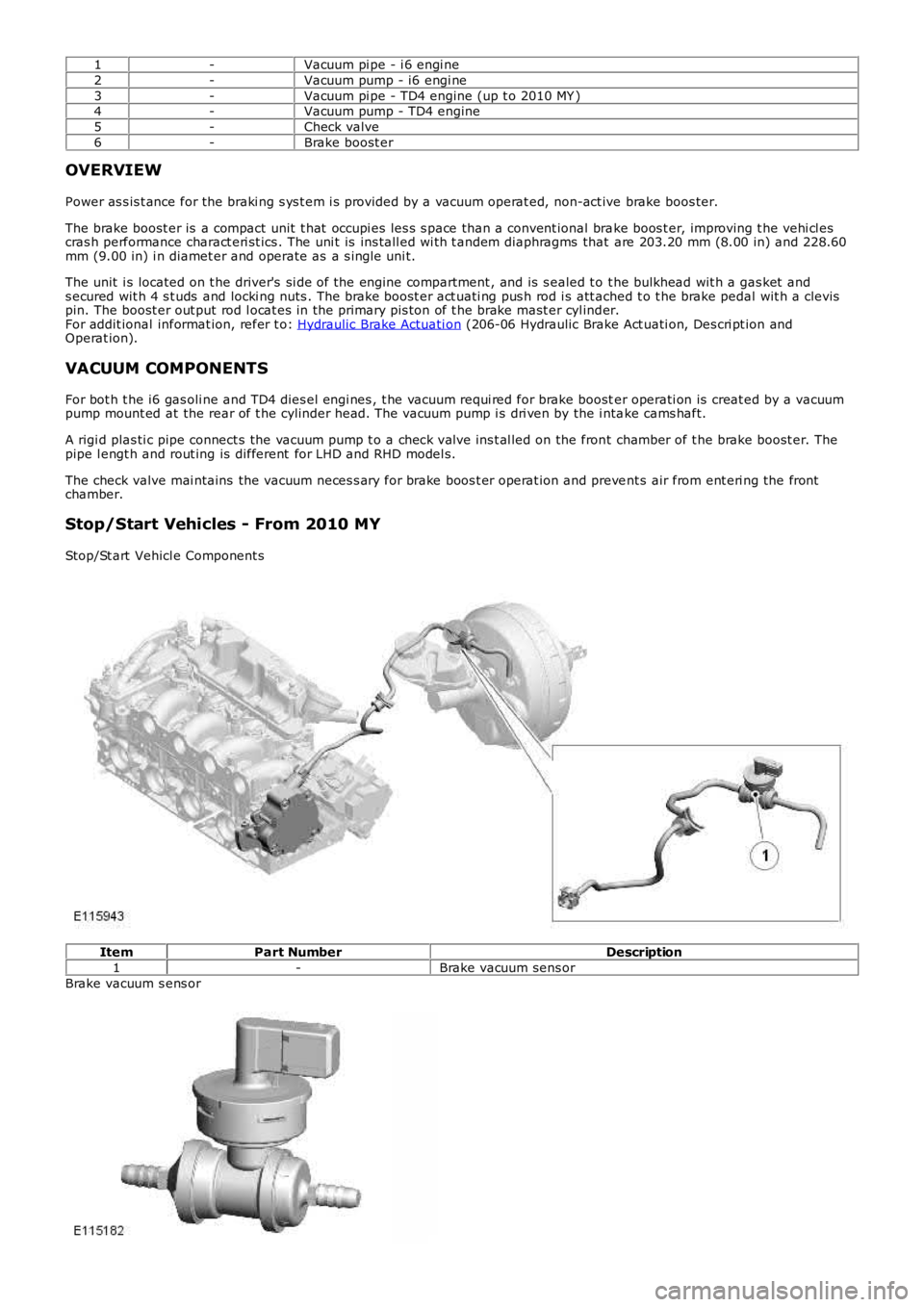
1-Vacuum pi pe - i 6 engi ne
2-Vacuum pump - i6 engi ne
3-Vacuum pi pe - TD4 engine (up t o 2010 MY )4-Vacuum pump - TD4 engine
5-Check valve
6-Brake boost er
OVERVIEW
Power as s is t ance for the braki ng s ys t em i s provided by a vacuum operat ed, non-act ive brake boos ter.
The brake boost er is a compact unit t hat occupi es les s s pace than a convent ional brake boos t er, improving t he vehi cl escras h performance charact eri st ics . The uni t is ins tall ed wi th t andem diaphragms that are 203.20 mm (8.00 in) and 228.60mm (9.00 in) i n diamet er and operate as a s ingle uni t.
The unit i s located on t he driver's si de of the engine compartment , and is s ealed t o t he bulkhead wit h a gas ket ands ecured wit h 4 s t uds and locki ng nuts . The brake boost er act uati ng pus h rod i s att ached t o t he brake pedal wit h a clevispin. The boost er out put rod l ocat es in the primary pis ton of t he brake mast er cyl inder.For addit ional informat ion, refer t o: Hydraulic Brake Actuati on (206-06 Hydraulic Brake Act uati on, Des cri pt ion andOperat ion).
VACUUM COMPONENTS
For bot h t he i6 gas oli ne and TD4 dies el engi nes , t he vacuum requi red for brake booster operati on is creat ed by a vacuumpump mount ed at the rear of t he cylinder head. The vacuum pump i s dri ven by the i ntake cams haft.
A rigi d plas ti c pipe connect s the vacuum pump t o a check valve ins t al led on the front chamber of t he brake boost er. Thepipe l engt h and rout ing is different for LHD and RHD model s.
The check valve mai ntains the vacuum neces s ary for brake boos t er operat ion and prevent s air from ent eri ng the frontchamber.
Stop/Start Vehicles - From 2010 MY
Stop/St art Vehicl e Component s
ItemPart NumberDescription
1-Brake vacuum sens or
Brake vacuum s ens or
Page 500 of 3229
1
2
Publi s hed: 11-May-2011
Anti-Lock Control - Anti-Lock Control
Diagnosi s and Tes ti ng
Principles of Operation
For a detail ed descripti on of the Ant i-lock Braking Sys t em (ABS), refer to the relevant Des cri pt ion and Operati on s ect ion i nt he works hop manual . REFER t o: Anti -Lock Cont rol - St abi li ty As s is t (206-09C Anti -Lock Cont rol - St abi lit y As s is t,Des cript ion and Operat ion).
Inspection and Verification
CAUTION: Di agnos is by s ubs ti tut ion from a donor vehicle is NO T acceptabl e. Subs ti tut ion of cont rol modules doesnot guarant ee confirmat ion of a faul t, and may als o caus e addit ional fault s i n t he vehi cl e being t est ed and/or t he donorvehi cl e.
• NOTE: Pri or to any t es ti ng or ins pect ion, the vehicle should be check for any relevant warning l amps bei ng il lumi nat ed. Ifa warning l amp is ill uminat ed, check for DTCs and refer to t he relevant DTC Index, if no warni ng lamp is i ll uminated,cont inue wi th diagnos t ic procedures below.
1. Verify t he cus t omer concern.1.
2. Vis ually ins pect for obvious s igns of damage and s ys t em i ntegri ty.
Visual InspectionMechanicalElectrical
Brake flui d levelVacuum s ys t emW heel s peed sens or ins tall ati onW heel s peed sens or ai r gapSt eering wheel rot ati on sens orAccel erometer/s ens or clus t er i nst all ati onIncorrect wheel or t ire s ize
W arning light operat ionFus esW heel s peed s ens orsConnect ors /Pi nsHarnes s esSt eering wheel rot ati on s ens orAccel eromet er/sens or cl ust erHydraul ic Control Uni t (HCU)
2.
3. If an obvious cause for an obs erved or report ed concern is found, correct t he caus e (if pos s ible) beforeproceeding t o t he next s t ep3.
4. If t he caus e is not vis ually evi dent , check t he ant i-lock braking sys tem and s teering rot ati on s ens or modules forDi agnos ti c Trouble Codes (DTCs) and refer t o t he rel evant DTC Index.4.
DTC Index
• NOTE: If the control modul e or a component i s s us pect and the vehicle remains under manufacturer warrant y, refer t o theW arranty Pol icy and Procedures manual (s ect ion B1.2), or determine i f any pri or approval programme is in operat ion, pri ort o the ins tall ati on of a new module/component.
• NOTE: Generic scan t ool s may not read the codes li st ed, or may read only fi ve digit codes . Mat ch the five di git s from t hes can tool to the firs t fi ve di git s of the seven digi t code l is ted to ident ify t he faul t (t he las t t wo digi ts gi ve addi ti onalinformat ion read by the manufact urer approved diagnos t ic s ys tem).
• NOTE: W hen performing volt age or res is t ance t est s , always use a digi tal mult imeter (DMM) accurat e t o t hree deci malplaces, and wi th an up-t o-date cal ibrat ion cert ificate. W hen tes ti ng res is t ance al ways take t he res is t ance of t he DMMleads i nt o account .
• NOTE: Check and recti fy bas ic faul ts before beginni ng diagnos t ic rout ines i nvol vi ng pinpoint t es t s.
• NOTE: Ins pect connect ors for s igns of water ingres s , and pins for damage and/or corros ion.
• NOTE: If DTCs are recorded and, aft er performi ng the pi npoi nt tes ts , a fault is not present , an int ermi tt ent concern maybe t he caus e. Always check for loose connect ions and corroded terminals .
For a compl ete lis t of all Di agnos ti c Trouble Codes (DTCs) t hat could be logged on this vehicle, pleas e refer to Sect ion100-00.REFER t o: Di agnos t ic Trouble Code (DTC) Index - DTC: Ant i-Lock Braki ng Sys t em (ABS) (100-00 GeneralInformat ion, Des cript ion and Operat ion).
Pinpoint Tests
PINPOINT TEST A : BRAKE VACUU M ASSIST FU NCTION
T ESTCONDIT IONSDET AILS/RESULT S/ACT IO NS
A1: CHECK T HE BRAKE PEDAL T R AVEL WIT H T HE ENGINE OFF
Set i gnit ion s wit ch t o OFF.
Pump t he brake pedal s ix ti mes and hold firm press ure on t he pedal .
Did t he pedal t ravel decreas e and t he pedal go hard as i t was pumped?YesGO t o A2.NoCHECK the vacuum circui t to the brake boos t er. Start the engine and idle for three mi nut es, s wi tchignit ion OFF t hen repeat t he tes t. If t he pedal t ravel does not decreas e, s uspect the brake boos t er.
A2: CHECK T HE BRAKE PEDAL T R AVEL WIT H T HE ENGINE RUNNING
Page 528 of 3229
Publi s hed: 11-May-2011
Steering System - General Information - Steering System
Diagnosi s and Tes ti ng
Principle of Operation
For a detail ed descripti on of the st eering sys tem, refer t o t he rel evant Des cript ion and Operat ion s ecti on in the works hopmanual. REFER to:
Steeri ng Sys t em (211-00 St eering Sys tem - General Informat ion, Diagnos i s and Test ing),Power St eering (211-02 Power Steeri ng, Des cri pti on and Operati on),Steeri ng Linkage (211-03 St eering Li nkage, Descripti on and Operat ion),Steeri ng Column (211-04 St eering Col umn, Des cri pti on and Operati on).
Inspection and Verification
1. Verify t he cus t omer concern by operat ing t he s yst em.1.
2. Vis ually ins pect for obvious s igns of damage and s ys t em i ntegri ty.2.
Visual Inspection
MechanicalCheck the t ires for correct press ure, s ize and t read pat ternCheck for wheel rim and t ire damageCheck road wheel securi tyCheck the power s teeri ng fluid level and t he hydraulic ci rcuit for flui d leaksCheck the power s teeri ng pump drive belt condi ti on and t ens ionCheck the power s teeri ng pump for securi ty, wear, damage and exces s ive nois eCheck the s t eering gear as sembl y for damage, wear and s ecurit yCheck the hydrauli c pipes and cool er li nes for damage and correct rout ingCheck the s t eering joint s for damage, excess i ve play, wear and s ecurit yCheck the s t eering column and joi nt s for damage, exces s ive play, wear and securi ty
3. If an obvious cause for an obs erved or report ed concern is found, correct t he caus e (if pos s ible) beforeproceeding t o t he next s t ep.3.
4. If t he concern is not vis uall y evi dent , verify t he s ymptom and refer t o t he Symptom Chart .4.
Symptom Chart
• NOTE: If a component is sus pect and t he vehicle remains under the manufact urer warrant y, refer t o t he W arrant y Policyand Procedures manual (s ect ion B1.2), or determine i f any prior approval programme is i n operat ion, prior t o t heins t al lat ion of a new component.
SymptomPossible CauseAction
St eering wandersExces s ive free pl ay in t hes teering s yst emSt eering geometryi ncorrect ly al igned
Check for excess i ve movement or play i n t he s teeri ng s yst em wit hthe engine running. Check for pl ay at several different s t eeringpos i ti ons . Carry out st eeri ng geomet ry and alignment checks .REFER t o: Four-W heel Al ignment (204-00 Sus pens i on Sys t em -General Informati on, General Procedures ).St eering pull s t o t hel eft or ri ghtSt eering/s us pens ioncomponent s damaged,bent, l oos eSt eering geometryi ncorrect ly al igned
Check s t eering and s us pens ion component s for damage/correctins tal lati on. Carry out s t eering geometry and ali gnment checks .REFER t o: Four-W heel Al ignment (204-00 Sus pens i on Sys t em -General Informati on, General Procedures ).
St eering feel snotchy when t urningfrom lock to lock
St eering or s uspens ions wivel joi nt s s eizedSt eering t ie rod end jointsor t rack rod i nner joint ss eizedSt eering column orunivers al joi nt s s eizedSt eering gear int ernalcomponent s mi sal igned,worn or damaged
Dis connect the s t eering gear from the s us pens ion. Check forfreedom of movement i n t he s us pensi on. Di s connect t he s teeringcol umn from the s t eering gear. Check t he st eeri ng col umn anduni vers al joint s for freedom of movement. Check the s t eeringgear for freedom of movement . Rect ify as neces s ary.
St eering feel s t ightand does nots elf-center
Power st eeri nghydrauli cs noi syoperat ion
Power st eeri ng fl uid l evell ow or cont aminatedPower st eeri ng fl uidaerat edPower st eeri ng hos est wis t ed or res tricted
Check and t op-up t he power st eering fl ui d l evel if requi red.REFER t o: Power St eeri ng Sys t em Bl eeding (211-00 St eeringSys t em - General Informat ion, General Procedures ).Check for contaminated flui d. Check for air i ngres s int o t hesys t em. Check t he power s t eering hos es for t wis t ing orres trict ions. Recti fy as neces sary.
Power st eeri ng pumpnois yPower st eeri ng fl uid l evell ow or cont aminatedPump i nternal component sworn or damaged
Check and t op-up t he power st eering fl ui d l evel if requi red.REFER t o: Power St eeri ng Sys t em Bl eeding (211-00 St eeringSys t em - General Informat ion, General Procedures ).Check for contaminated flui d. Check for exces s ive pump noi se.Ins tal l a new pump as required. Refer t o t he new componentins tal lati on note at t he t op of the Sympt om Chart