2006 LAND ROVER FRELANDER 2 check engine
[x] Cancel search: check enginePage 530 of 3229
Publi s hed: 11-May-2011
Steering System - General Information - Power Steering System Bleeding
General Procedures
Clean power s teering fluid res ervoir around t he fi ll er cap and flui di ndi cat or.1.
Check the power s teeri ng fluid, if aerat ed, wait unti l fl ui d i s freefrom bubbles then t op-up res ervoi r to UPPER l evel mark wit hrecommended fluid.
2.
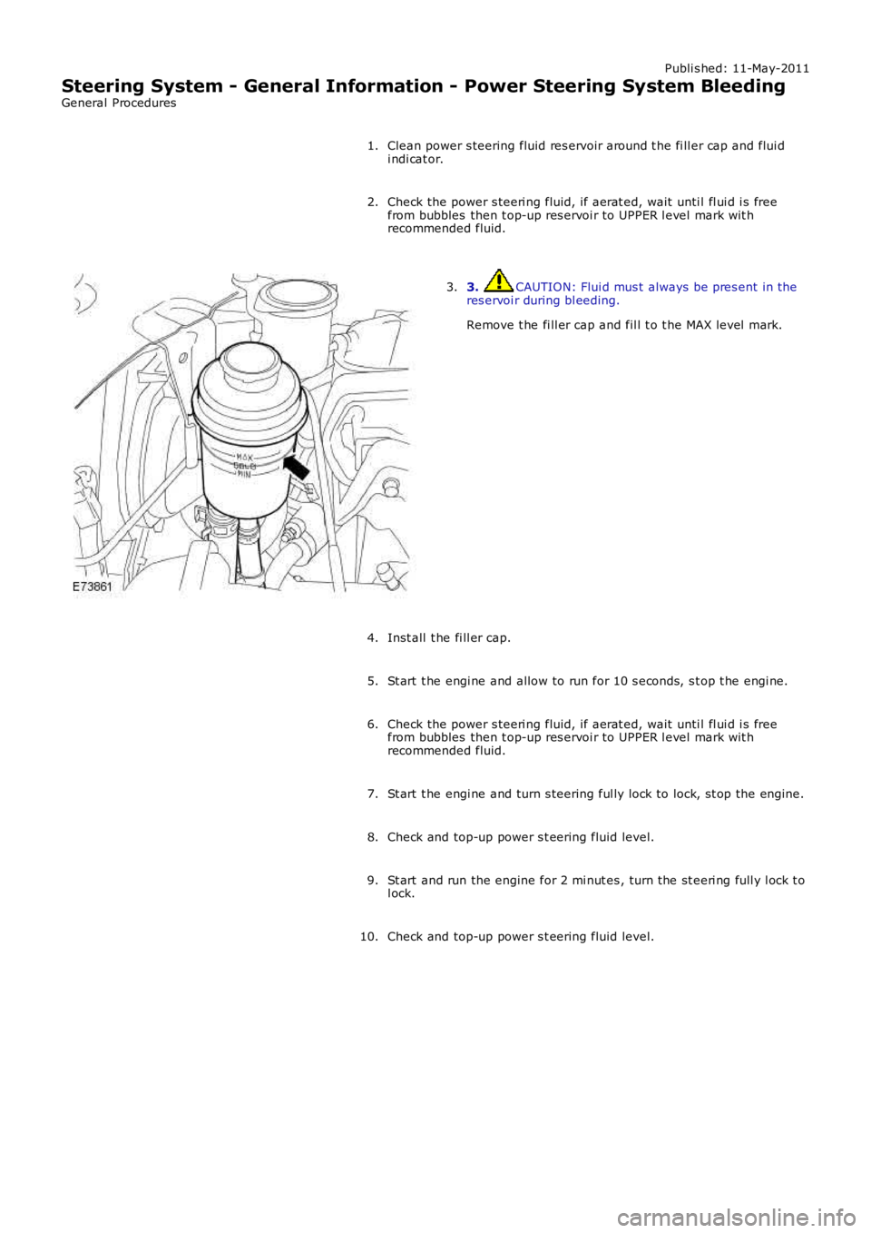
3. CAUTION: Flui d mus t always be pres ent in theres ervoi r during bl eeding.
Remove t he fi ll er cap and fil l t o t he MAX level mark.
3.
Inst all t he fi ll er cap.4.
St art t he engi ne and allow to run for 10 s econds, s t op t he engi ne.5.
Check the power s teeri ng fluid, if aerat ed, wait unti l fl ui d i s freefrom bubbles then t op-up res ervoi r to UPPER l evel mark wit hrecommended fluid.
6.
St art t he engi ne and turn s teering ful ly lock to lock, s t op the engine.7.
Check and top-up power s t eering fluid level.8.
St art and run the engine for 2 mi nut es , turn the st eeri ng full y l ock t ol ock.9.
Check and top-up power s t eering fluid level.10.
Page 541 of 3229
3-Pres s ure out put port (t o s t eering gear val ve unit )
The pump i s a fixed dis placement, vane type pump which s uppl ies hydrauli c pres sure to t he st eeri ng gear valve unit . Thepump i s located at t he rear of t he engi ne and is driven by t he Rear Engi ne Auxi liary Drive (READ) Poly Vee bel t which i sindirect ly driven from t he cams haft s . The pump s uppl ies a cons tant fl ow rate, t herefore the out put i s i ndependent ofpump/engine s peed. A s el f-adjus ti ng tens ioner is fit t ed to maint ai n t he correct t ension on the bel t.
The pump contains a number of vanes which rot ate wit hin a cam ri ng and are driven by t he i nput s haft . As the vanesrot ate, t he cam ring causes t he s pace bet ween the vanes t o increas e. Thi s caus es a depres s ion bet ween the vanes andfl uid i s drawn from t he res ervoir vi a t he suct ion hos e int o t he s pace between the vanes. As t he s haft rotat es , t he inl etport i s clos ed to the vanes which have drawn in fluid, t rapping t he fluid bet ween t he vanes . The cam ring caus es t he s pacebetween t he vanes to reduce and cons equenti ally compress es and pres s uri zes t he hydrauli c fl ui d t rapped between t hem.Furt her rotat ion of t he s haft moves the vanes t o the out let port . As t he vanes pas s t he port plat e t he pres surized fluidpass es from the pump out let port into the press ure hose to the s t eering gear.
The pres s urized fluid is s ubject t o cont rol by a flow cont rol and pres s ure relief valve. The fl ow control valve maintai ns acons t ant flow of flui d s uppl ied t o t he s teeri ng gear irres pecti ve of engi ne s peed variati ons . The pres s ure reli ef val ve limit st he maximum pres sure on t he output s ide of t he pump. A met eri ng orifice i s included i n t he dis charge port of the pump.
If the pres s ure in t he ori fi ce reaches a predetermined l evel , a s pring loaded bal l in t he cent re of the flow cont rol valve isli ft ed from it s s eat and al lows pres s uri zed flui d t o recircul ate wit hi n t he pump. The pres sure rel ief valve wi ll operate if t hedis charge from the pump is rest ri ct ed, for example, s teeri ng held on full l ock. If the output from the pump is bl ocked, al loutput is recirculat ed t hrough the pump. In t his condi ti on, as no fresh fl ui d i s drawn i nto the pump from t he res ervoir, thefl uid t emperat ure i nsi de t he pump wil l increas e rapi dl y. Cons equent iall y, periods of operati on of the s t eering gear on ful llock s houl d be kept to a mi nimum to prevent overheati ng of the pump and the flui d within it .
The pump has an i nternal pres s ure reli ef valve whi ch als o i ncorporat es a flow cont rol val ve. The press ure rel ief val ve li mit s
t he maximum pres sure s uppl ied t o t he s teering gear to 125 bar (1812 lbf in2) ± 4 bar (58 l bf in2). The flow control val ve
li mit s t he maximum flow t o 8.8 l/mi n (1.93 gal/min) ± 0.5 l/min (0.1 gal/min) at 10 bar (145 bf i n2) The pump has a
dis placement of 11 cc/rev (0.67 i n3/rev).
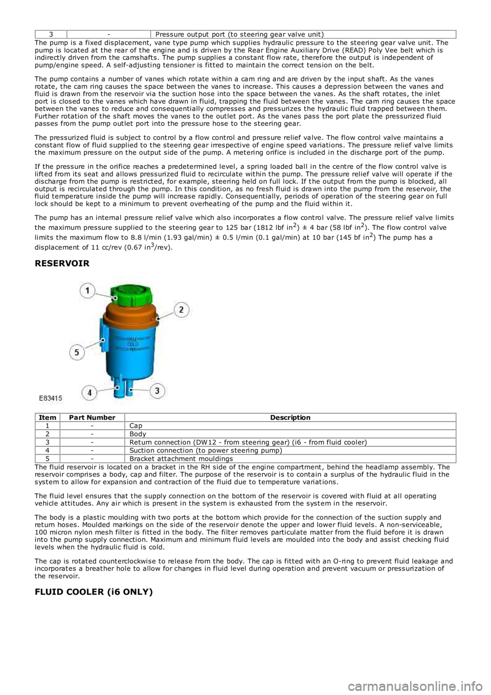
RESERVOIR
ItemPart NumberDescription1-Cap
2-Body
3-Ret urn connect ion (DW 12 - from s teering gear) (i6 - from fluid cool er)4-Sucti on connecti on (t o power s teeri ng pump)
5-Bracket att achment moul dings
The fl uid res ervoi r is locat ed on a bracket in the RH s ide of t he engi ne compartment, behi nd t he headl amp as sembl y. Theres ervoir compri s es a body, cap and filt er. The purpos e of t he res ervoir i s t o cont ain a surplus of t he hydraul ic fluid in thes ys t em t o al low for expans ion and cont ract ion of t he fl uid due t o t emperature vari ations .
The fl uid l evel ens ures t hat t he s uppl y connecti on on t he bot t om of t he res ervoir i s covered wit h fluid at al l operat ingvehi cl e at ti tudes. Any ai r which is pres ent i n t he s ys t em i s exhaus ted from t he s ys tem i n t he res ervoir.
The body is a plas ti c moulding wit h two port s at the bot tom which provi de for t he connecti on of the s ucti on supply andret urn hos es . Moul ded markings on the s ide of t he reservoi r denot e the upper and lower fluid level s . A non-s erviceable,100 mi cron nylon mes h fil ter is fi tt ed in the body. The fi lt er removes parti cul ate matt er from t he fl uid before i t is drawnint o t he pump s uppl y connecti on. Maximum and minimum fluid level s are moulded int o the body and ass is t checking fl ui dlevels when the hydrauli c fl uid i s cold.
The cap is rotat ed count erclockwi s e t o rel eas e from t he body. The cap is fit t ed wit h an O-ri ng t o prevent fl ui d l eakage andincorporat es a breat her hol e to allow for changes i n fluid level duri ng operati on and prevent vacuum or pres s uri zat ion oft he res ervoir.
FLUID COOLER (i6 ONLY)
Page 603 of 3229
Publi s hed: 23-Aug-2011
Engine - I6 3.2L Petrol -
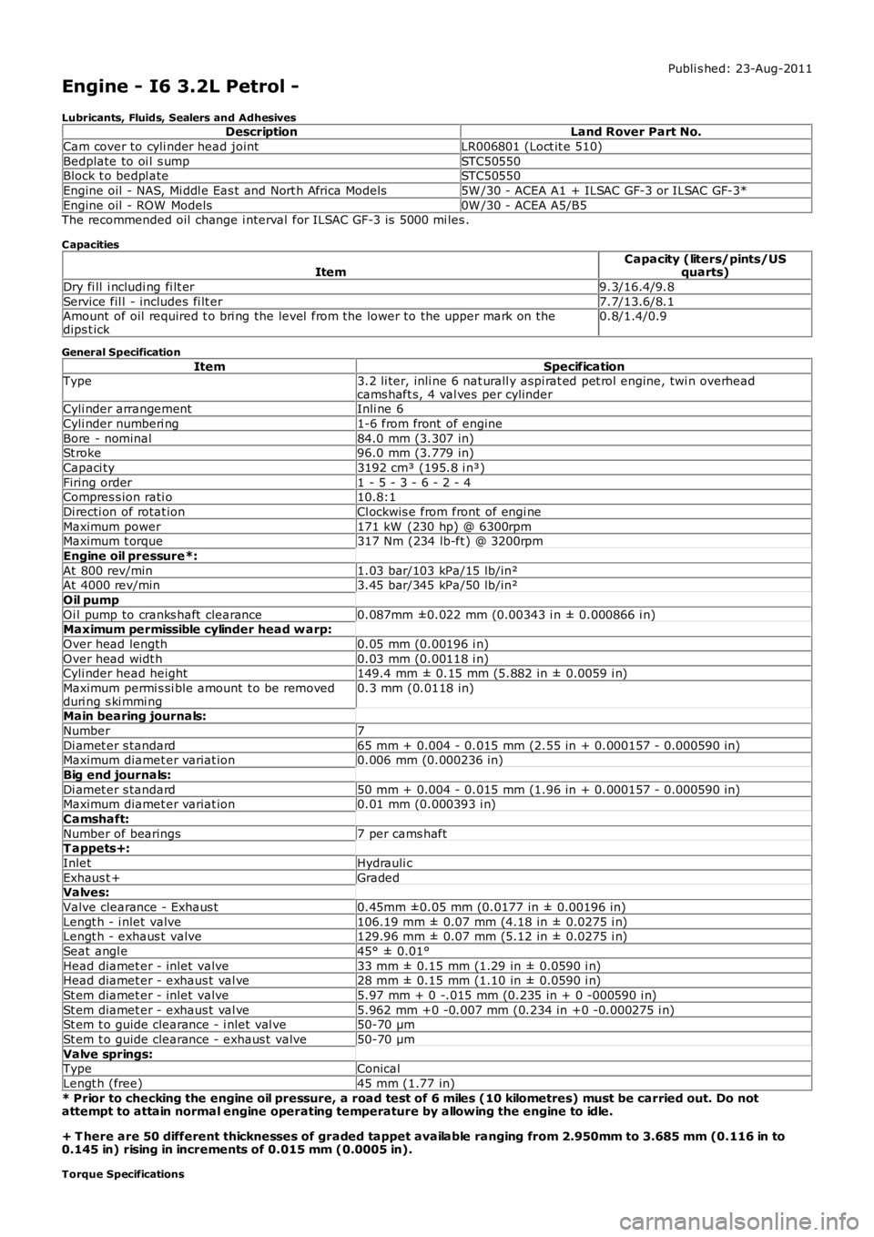
Lubricants, Fluids, Sealers and AdhesivesDescriptionLand Rover Part No.
Cam cover to cyli nder head jointLR006801 (Loct it e 510)
Bedplate to oi l s umpSTC50550Block t o bedpl ateSTC50550
Engine oil - NAS, Mi ddl e Eas t and Nort h Africa Models5W /30 - ACEA A1 + ILSAC GF-3 or ILSAC GF-3*
Engine oil - ROW Models0W /30 - ACEA A5/B5The recommended oil change i nterval for ILSAC GF-3 is 5000 mi les .
C apacities
ItemCapacity (liters/pints/USquarts)
Dry fi ll i ncludi ng fi lt er9.3/16.4/9.8
Service fil l - includes fi lt er7.7/13.6/8.1Amount of oil required t o bri ng the level from the lower to the upper mark on thedips t ick0.8/1.4/0.9
General Specification
ItemSpecificationType3.2 li ter, inli ne 6 nat urall y aspi rat ed pet rol engine, twi n overheadcams haft s, 4 val ves per cylinderCyli nder arrangementInli ne 6
Cyli nder numberi ng1-6 from front of engine
Bore - nominal84.0 mm (3.307 in)St roke96.0 mm (3.779 in)
Capaci ty3192 cm³ (195.8 i n³)
Firing order1 - 5 - 3 - 6 - 2 - 4Compres s ion rati o10.8:1
Di recti on of rotat ionCl ockwis e from front of engi ne
Maximum power171 kW (230 hp) @ 6300rpmMaximum t orque317 Nm (234 lb-ft ) @ 3200rpm
Engine oil pressure*:
At 800 rev/min1.03 bar/103 kPa/15 lb/in²At 4000 rev/min3.45 bar/345 kPa/50 lb/in²
Oil pump
Oi l pump to cranks haft clearance0.087mm ±0.022 mm (0.00343 i n ± 0.000866 i n)Maximum permissible cylinder head w arp:
Over head length0.05 mm (0.00196 i n)
Over head widt h0.03 mm (0.00118 i n)Cyli nder head height149.4 mm ± 0.15 mm (5.882 in ± 0.0059 i n)
Maximum permi s si ble amount t o be removedduri ng s ki mmi ng0.3 mm (0.0118 in)
Main bearing journals:
Number7
Di amet er s tandard65 mm + 0.004 - 0.015 mm (2.55 in + 0.000157 - 0.000590 in)Maximum diamet er variat ion0.006 mm (0.000236 in)
Big end journals:
Di amet er s tandard50 mm + 0.004 - 0.015 mm (1.96 in + 0.000157 - 0.000590 in)Maximum diamet er variat ion0.01 mm (0.000393 i n)
Camshaft:
Number of bearings7 per cams haftT appets+:
InletHydrauli c
Exhaus t +GradedValves:
Valve clearance - Exhaus t0.45mm ±0.05 mm (0.0177 in ± 0.00196 in)
Lengt h - i nlet valve106.19 mm ± 0.07 mm (4.18 in ± 0.0275 i n)Lengt h - exhaus t valve129.96 mm ± 0.07 mm (5.12 in ± 0.0275 i n)
Seat angl e45° ± 0.01°
Head diamet er - inlet valve33 mm ± 0.15 mm (1.29 in ± 0.0590 i n)Head diamet er - exhaus t val ve28 mm ± 0.15 mm (1.10 in ± 0.0590 i n)
St em diamet er - inlet valve5.97 mm + 0 -.015 mm (0.235 in + 0 -000590 i n)
St em diamet er - exhaus t val ve5.962 mm +0 -0.007 mm (0.234 in +0 -0.000275 i n)St em t o guide clearance - i nlet val ve50-70 µm
St em t o guide clearance - exhaus t valve50-70 µm
Valve springs:TypeConical
Lengt h (free)45 mm (1.77 in)
* Prior to checking the engine oil pressure, a road test of 6 miles (10 kilometres) must be carried out. Do notattempt to attain normal engine operating temperature by allowing the engine to idle.
+ T here are 50 different thicknesses of graded tappet available ranging from 2.950mm to 3.685 mm (0.116 in to0.145 in) rising in increments of 0.015 mm (0.0005 in).
Torque Specifications
Page 646 of 3229
Publi s hed: 11-May-2011
Engine - I6 3.2L Petrol - Engine
Diagnosi s and Tes ti ng
Principles of Operation
For a detail ed descripti on of the engine sys tem, refer t o t he rel evant Des cript ion and Operat ion s ecti on in the works hopmanual.REFER to: Engine (303-01A Engine - I6 3.2L Pet rol , Des cri pti on and Operati on).
Inspection and Verification
1. Verify t he cus t omer concern.1.
2. Vis ually ins pect for obvious s igns of mechani cal or electrical damage.2.
Visual Inspection
MechanicalElectrical
Coolant leaksOi l leaksLeaks in t he fuel s yst emVis i bl y damaged or worn partsLoose or mis s ing fixings
Fus esLoos e or corroded el ect ri cal connectorsHarnes sesSens ors
3. If an obvious cause for an obs erved or report ed concern is found, correct t he caus e (if pos s ible) beforeproceeding t o t he next s t ep3.
4. If t he caus e is not vis ually evi dent , verify t he sympt om and refer t o t he Sympt om Chart.4.
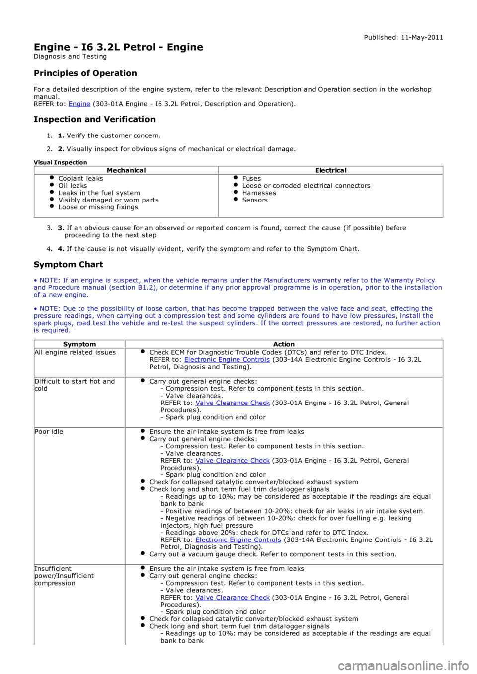
Symptom Chart
• NOTE: If an engi ne is sus pect , when the vehicl e remai ns under t he Manufact urers warranty refer t o t he W arranty Pol icyand Procedure manual (s ect ion B1.2), or determine if any pri or approval programme is in operat ion, pri or t o t he i ns t allat ionof a new engine.
• NOTE: Due t o t he poss ibi li ty of l oos e carbon, that has become trapped bet ween t he val ve face and s eat, effect ing thepres s ure readi ngs , when carryi ng out a compres s ion t est and s ome cyli nders are found t o have low press ures , i ns t all thes park plugs , road t est the vehicle and re-t es t the s us pect cylinders . If the correct pres sures are rest ored, no furt her acti onis required.
SymptomAction
All engine relat ed is s uesCheck ECM for Di agnos t ic Trouble Codes (DTCs) and refer t o DTC Index.REFER t o: El ect ronic Engi ne Cont rol s (303-14A El ect roni c Engi ne Cont rol s - I6 3.2LPet rol, Di agnos is and Tes ti ng).
Di fficul t t o s tart hot andcoldCarry out general engi ne checks :- Compress ion tes t. Refer t o component t es ts i n t his s ect ion.- Val ve cl earances .REFER t o: Val ve Clearance Check (303-01A Engine - I6 3.2L Pet rol , GeneralProcedures ).- Spark pl ug condi ti on and col or
Poor idleEns ure t he air i ntake s yst em is free from leaksCarry out general engi ne checks :- Compress ion tes t. Refer t o component t es ts i n t his s ect ion.- Val ve cl earances .REFER t o: Val ve Clearance Check (303-01A Engine - I6 3.2L Pet rol , GeneralProcedures ).- Spark pl ug condi ti on and col orCheck for collaps ed catalyt ic converter/blocked exhaus t s ys t emCheck long and s hort t erm fuel t rim datal ogger s ignals- Readings up t o 10%: may be cons idered as acceptable if t he readings are equalbank t o bank- Pos it ive readi ngs of bet ween 10-20%: check for air leaks i n air i nt ake s ys t em- Negati ve readings of between 10-20%: check for over fuell ing e.g. leaki ngi njectors , high fuel pres sure- Readings above 20%: check for DTCs and refer t o DTC Index.REFER t o: El ect ronic Engi ne Cont rol s (303-14A El ect roni c Engi ne Cont rol s - I6 3.2LPet rol, Di agnos is and Tes ti ng).Carry out a vacuum gauge check. Refer to component t es ts i n t his s ecti on.
Insuffi ci entpower/Ins ufficientcompres s ion
Ens ure t he air i ntake s yst em is free from leaksCarry out general engi ne checks :- Compress ion tes t. Refer t o component t es ts i n t his s ect ion.- Val ve cl earances .REFER t o: Val ve Clearance Check (303-01A Engine - I6 3.2L Pet rol , GeneralProcedures ).- Spark pl ug condi ti on and col orCheck for collaps ed catalyt ic converter/blocked exhaus t s ys t emCheck long and s hort t erm fuel t rim datal ogger s ignals- Readings up t o 10%: may be cons idered as acceptable if t he readings are equalbank t o bank
Page 647 of 3229
SymptomAction
- Pos it ive readi ngs of bet ween 10-20%: check for air leaks i n air i nt ake s ys t em- Negati ve readings of between 10-20%: check for over fuell ing e.g. leaki ngi njectors , high fuel pres sure- Readings above 20%: check for DTCs and refer t o DTC Index.REFER t o: El ect ronic Engi ne Cont rol s (303-14A El ect roni c Engi ne Cont rol s - I6 3.2LPet rol, Di agnos is and Tes ti ng).Carry out a vacuum gauge check. Refer to component t es ts i n t his s ecti on.
Oi l cons umpti onCarry out oil l eak check fol lowed by an oi l cons umpt ion tes t. Refer t o t he componentt est s i n t hi s s ect ionIf oil cons umpt ion i s exces si ve:Check the integrit y of the engine breat her sys t emCarry out general engi ne checks :- Compress ion tes t. Refer t o component t es ts i n t his s ect ion.- Val ve cl earances .REFER t o: Val ve Clearance Check (303-01A Engine - I6 3.2L Pet rol , GeneralProcedures ).- Spark pl ug condi ti on and col or
Nois eRefer t o t he Speci al Servi ce Mess ages on t he Electroni c Product Q ual it y Report (EPQR)s ys tem for s ound fi les . If t he s ympt om does NOT compare t o any of the s ound files ,contact Deal er Technical Support (DTS).
Component Tests
Engine Oil Leaks
• NOTE: Before ins t al li ng new gasket s or oil s eal s, make sure t hat t he faul t is cl early es t abl is hed.
If the oi l l eak cannot be ident ifi ed clearl y by a vi sual ins pect ion, carry out an Ult raviolet t est :
Fluorescent Oil Additive Method
1. Clean t he engi ne wit h a sui table cl eani ng fl uid (brake cleaner).1.
2. Drai n the engi ne oil and refil l wit h recommended oil , premixed wi th Dies el Engine Oil Dye or equi val ent . Us e aminimum 14.8 ml (0.5 ounce) t o a maxi mum 29.6 ml (1 ounce) of fl uores cent addit ive to all engines. If oil i s notpremixed, fl uorescent addi ti ve mus t fi rs t be added to the crankcas e.
2.
3. Run engi ne for 15 minutes . Stop the engine and i nspect all s eal and gas ket areas for leaks us ing a 12 Vol tMas t er UV Diagnost ic Ins pect ion Ki t or equivalent . A clear bri ght yell ow or orange area wil l i dent ify l eak. Forext remely smal l leaks, s everal hours may be required for t he leak t o appear.
3.
4. As neces s ary, pres surize t he main oil gallery s yst em t o l ocat e leaks due t o incorrect ly sealed, loos e or cockedpl ugs . If the flywheel bol ts l eak oil, l ook for s ealer on t he threads .4.
5. Repai r al l leaks as neces s ary.5.
Compression Test
General Remarks
• NOTE: Removing fuses and di sconnect ing elect rical components may caus e t he Engine Control Modul e (ECM) t o l ogDiagnost ic Troubl e Codes (DTCs ). Aft er t he meas urements have been carried out , DTCs should be cl eared from memory byconnecti ng to the Manufact urer Approved Diagnos t ic Sys tem.
• NOTE: Only check the compress ion pres sure wit h t he valves s et to the pres cri bed clearance (i f thi s can be adjus ted).
The compres si on pres s ure s hould be checked wi th the engine at operat ing temperat ure.
Check the Comp ression Pressure
W ARNING: Move gear s elector lever to 'P' pos i ti on. Fail ure t o follow thi s ins t ructi on may res ult i n pers onal injury.
1. Remove the fuel pump rel ay.1.
2. Start the engine - the engine wi ll s t art, run for a few seconds then s t op.2.
3. Remove the s park pl ugs.3.
4. Ins t al l the compres s ion t es ter.4.
5. Ins t al l an auxi li ary s tarter s wit ch in the st art ing circui t. W it h t he ignit ion swi tch O FF, us ing t he auxi li ary s t arters wi tch, crank the engine a mi ni mum of five compres s ion st rokes and record the hi ghest reading. Not e theapproximat e number of compress i on s trokes requi red t o obt ai n t he highest readi ng.
5.
6. Repeat t he tes t on each cyl inder, cranking t he engine approximat ely t he s ame number of compress i on st rokes .6.
7. Ins t al l the removed components in reverse order, obs erving t he s peci fi ed ti ght ening t orques.7.
8. Clear all DTCs from the ECM.8.
Page 648 of 3229
Interpretation of the Results
• NOTE: Due t o t he poss ibi li ty of l oos e carbon t hat has become t rapped between t he valve face and seat effect ing thepres s ure readi ngs , when carryi ng out a compres s ion t est and cyli nders are found to have low press ures , ins t al l the s parkplugs , road t est t he vehicle and re-t est the s us pect cyl inders . If the correct pressures are rest ored, no further acti on isrequired.
The indicat ed compress i on pres sures are cons idered wi thi n s pecificati on if t he l owest readi ng cyl inder is wi thi n 75% of t hehighest reading.
If the cyli nder pres s ures are found t o be l ow, carry out a l eakdown t est to det ermi ne the locat ion of t he faul t (i f anyleakback can be heard through t he engine breat her sys tem s uspect the pi st on rings , if any leakback can be heard throught he inlet s ys tem sus pect t he i nl et val ve or seat , if any leakback can be heard through the exhaus t mani fold sus pect t heexhaus t val ve or s eat . If t he meas urements for t wo cyl inders next t o each ot her are bot h t oo low then i t is very likely thatt he cyl inder head gas ket bet ween them is burnt t hrough. Thi s can als o be recognized by t races of engi ne oil in the coolantand/or cool ant i n t he engi ne oil ).
Oil Consump tion Test
The amount of oi l an engi ne uses will vary wit h t he way t he vehi cl e is driven i n addit ion t o normal engine-t o-enginevariat ion. This i s es pecial ly t rue during t he fi rs t 16,100 km (10,000 mil es) when a new engine i s bei ng broken i n or unt ilcert ai n i nt ernal components become condit ioned. Vehicles us ed i n heavy-dut y operati on may us e more oil . The fol lowingare exampl es of heavy-duty operat ion:
Trai ler towi ng appl icati onsSevere loading appli cat ionsSust ained high speed operat ion
Engi nes need oi l to lubri cat e t he fol lowing internal component s :
Cylinder block cyl inder wallsPis t ons and pi st on ringsInt ake and exhaus t val ve s temsInt ake and exhaus t val ve guidesAll i nt ernal engi ne component s
W hen t he pis t ons move downward, a t hi n film of oil i s left on the cyli nder wal ls . As t he vehi cl e is operated, s ome oil i sals o drawn int o t he combus t ion chambers pas t the i ntake and exhaus t valve s tem s eal s and burned.
The fol lowing are examples of condi ti ons that can affect oil consumpt ion rates :
Engi ne s izeOperat or driving habit sAmbient t emperaturesQuali ty and vi scos it y of oi lEngi ne is bei ng run in an overfil led condit ion (check t he oil level at least five minutes after a hot s hutdown wi th thevehi cl e parked on a level surface. The oi l level s hould not be above the top of t he cros s-hatched area and t he l et t er"F" i n FULL).
Operat ion under varyi ng condi ti ons can frequent ly be mi sl eadi ng. A vehi cl e t hat has been run for s everal t housand miles ons hort t rips or i n below-freezi ng ambient temperat ures may have cons umed a "normal" amount of oil . However, whenchecking t he engine oil l evel , it may meas ure up to the full mark on t he oil l evel indicator due t o dil uti on (condens ati onand fuel ) in t he engine crankcas e. The vehi cl e t hen might be driven at high s peeds on the hi ghway where t he condens at ionand fuel boil off. The next t ime t he engi ne oil is checked it may appear that a l it er of oi l was us ed i n about 160 km (100mi les ). Oi l cons umpti on rat e is about one l it er per 2,400 km (1,500 mil es).
Make s ure t he s elected engine oi l meets manufact urer s pecificati on and t he recommended API performance cat egory "SG"and SAE vis cos i ty grade as s hown in t he vehicle O wner's Gui de. It is al s o important t hat t he engine oi l i s changed at t heint ervals s peci fi ed for t he t ypi cal operati ng condi ti ons .
The fol lowing di agnos t ic procedure i s us ed to det ermi ne t he s ource of excess i ve oi l cons umpti on.
• NOTE: Oi l us e i s normal ly great er during the first 16,100 km (10,000 mi les ) of servi ce. As mil eage i ncreas es , oil us edecreas es . High s peed dri vi ng, towing, high ambi ent temperat ure and ot her factors may res ult in great er oil use.
1. Defi ne exces si ve cons umpti on, s uch as t he number of miles driven per li ter of oil used. Al so det ermine cust omersdriving habit s , such as s us tai ned hi gh s peed operat ion, t owing, ext ended i dle and other cons iderat ions.1.
2. Verify t hat the engine has no ext ernal oi l leaks as descri bed under Engine Oi l Leaks i n thi s s ect ion.2.
3. Carry out an oil cons umpti on t es t :
Run t he engi ne to normal operati ng t emperature. Swi tch engine OFF and al low oi l to drain back for at l eas tfi ve mi nut es .W i th vehi cl e parked on l evel s urface, check t he engi ne oil l evel.If required, add engine oil t o s et level exactl y t o t he FULL mark.Record t he vehi cl e mi leage.Ins t ruct the cus tomer t o return for a l evel check after driving t he vehi cle as us ual for 1,610 km (1000 mi les ).Check t he oil l evel under t he s ame condit ions and at the same locat ion as the i nit ial check.
3.
• NOTE: If the oi l cons umpti on rat e is unaccept abl e go t o St ep 4.
4. Check t he Posi ti ve Crankcas e Vent ilat ion (PCV) sys t em. Make sure t he s ys t em i s not pl ugged.4.
5. Check for pl ugged oi l drain-back holes i n t he cyl inder head and cyli nder bl ock.5.
6. Carry out a cyl inder compress ion tes t. Refer t o t he Compres s ion Tes t procedure in thi s s ect ion. Thi s can help6.
Page 649 of 3229
det ermi ne the source of oi l cons umpt ion such as valves , pi s ton rings or other areas .
7. Check valve guides for exces si ve gui de clearance. Ins tall new val ve st em seals aft er verifyi ng val ve guideclearance.7.
8. W orn or damaged i nternal engine component s can caus e exces s ive oi l cons umpti on. Small depos it s of oi l on t het ips of t he s park plugs can be a cl ue t o int ernal oi l cons umpti on.8.
Intake Manifold Vacuum Test
Bri ng t he engi ne to normal operati ng temperature. Connect a vacuum gauge or equi val ent t o t he i nt ake manifold. Run theengi ne at t he specified i dle s peed.
The vacuum gauge s hould read bet ween 51-74 kPa (15-22 i n-Hg) dependi ng upon the engine condit ion and t he alt it ude atwhich t he t es t i s performed. Subt ract 4.0193 kPa (1 in-Hg) from t he s peci fi ed reading for every 304.8 m (1,000 feet ) ofelevati on above s ea l evel .
The reading should be st eady. As necess ary, adjus t t he gauge damper cont rol (where us ed) if t he needl e is fl ut t eringrapi dl y. Adjust damper unti l needle moves eas il y wi thout exces si ve fl utt er.
Interpreting Vacuum G auge Readings
A careful s t udy of the vacuum gauge reading whi le t he engine i s idli ng wi ll help pi npoint t rouble areas. Al ways conductother appropri at e t es ts before arrivi ng at a final di agnos ti c deci s ion. Vacuum gauge readi ngs , alt hough hel pful, mus t beint erpret ed careful ly.
Mos t vacuum gauges have a normal band indicated on the gauge face.
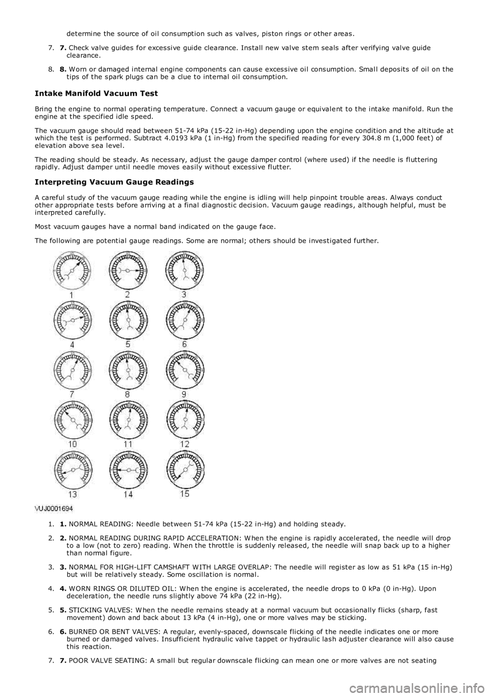
The fol lowing are pot ent ial gauge readings. Some are normal; ot hers s houl d be i nves ti gat ed furt her.
1. NORMAL READING: Needle bet ween 51-74 kPa (15-22 i n-Hg) and holding st eady.1.
2. NORMAL READING DURING RAPID ACCELERATION: W hen the engine i s rapi dl y accel erated, t he needle wil l dropt o a low (not to zero) reading. W hen t he t hrott le is s uddenl y rel eas ed, the needle will s nap back up to a highert han normal figure.
2.
3. NORMAL FOR HIGH-LIFT CAMSHAFT W ITH LARGE OVERLAP: The needle wi ll regi st er as low as 51 kPa (15 in-Hg)but wi ll be rel ati vel y s teady. Some oscil lat ion i s normal .3.
4. W ORN RINGS OR DILUTED OIL: W hen t he engine i s accelerated, the needle drops to 0 kPa (0 in-Hg). Upondecelerat ion, the needle runs s li ght ly above 74 kPa (22 in-Hg).4.
5. STICKING VALVES: W hen the needle remains s t eady at a normal vacuum but occas ionall y flicks (sharp, fastmovement ) down and back about 13 kPa (4 in-Hg), one or more val ves may be s ti cki ng.5.
6. BURNED OR BENT VALVES: A regul ar, evenl y-s paced, downs cale fli cking of t he needle i ndi cat es one or moreburned or damaged valves. Ins uffi cient hydraul ic valve t appet or hydrauli c las h adjus ter clearance wi ll als o causet his react ion.
6.
7. POOR VALVE SEATING: A smal l but regul ar downs cale fli cking can mean one or more valves are not seat ing7.
Page 651 of 3229

Publi s hed: 11-May-2011
Engine - I6 3.2L Petrol - Engine Oil Draining and Filling
General Procedures
• NOTE: Removal s t eps in t his procedure may cont ain i nst all ati on det ail s.
1. W ARNING: Make sure t o s upport the vehicle wit h axle
s tands .
Rais e and s upport t he vehi cl e.
1.
Remove t he oil fi lt er.
Refer t o: Oil Fil ter Element (303-01A Engi ne - I6 3.2L Pet rol,
Removal and Ins tall ati on).
2.
Remove t he engi ne undershi eld.
Refer t o: Engi ne Unders hi eld (501-02 Front End Body Panel s ,
Removal and Ins tall ati on).
3. 4. W ARNING: Avoi d s ki n cont act wit h t he
s peci fi ed material.
• CAUTIONS: Hot fluid.
Be prepared t o collect es caping flui ds .
T orque: 38 Nm Remove and dis card t he s ealing was her.4.
5. CAUTIONS: Make s ure that t he component is cl ean, free of foreign
mat eri al and l ubricant. Make s ure that new s eali ng washers are ins tall ed.
To i nst all , revers e t he removal procedure.
5.
Check and top-up the engine oi l.
6.