2006 LAND ROVER FRELANDER 2 check engine
[x] Cancel search: check enginePage 188 of 3229
For addit ional informat ion, refer t o: Parking Brake Cabl e Adjus tment (206-05 Parki ng Brake and Actuat ion, General
Procedures).
Door Locks and Hinges
1. Check operat ion of all door locks, bonnet lock and fuel fi ll er flap.
2. Lubricate al l door check s t raps , bonnet cat ch and fuel fill er fl ap cat ch.
Cooling System CAUTION:
Anti-freeze concentration must be maintained at 50%.
1. Check s peci fi c gravit y of cool ant us ing a hydrometer.
• NOTE: A s uit able hydromet er is avail abl e from the Equipment Programme under Part N umber 511 3302 001 00.
2. Top-up cool ing s ys tem if neces s ary.
For addit ional informat ion, refer t o: Specificati ons (303-03B Engine Cool ing - TD4 2.2L Dies el, Speci fi cat ions ).
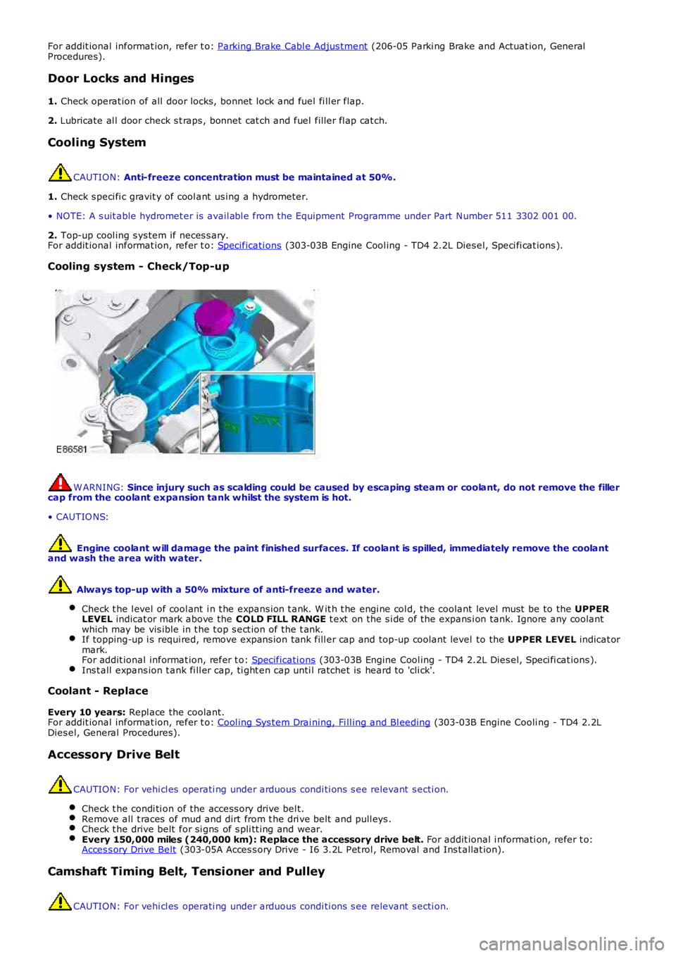
Cooling system - Check/Top-up W ARNING:
Since injury such as scalding could be caused by escaping steam or coolant, do not r emove the filler
cap from the coolant expansion tank whilst the system is hot.
• CAUTIO NS:
Engine coolant w ill damage the paint finished surfaces. If coolant is spilled, immed iately remove the coolant
and wash the area with water.
Always top-up with a 50% mixture of anti-freeze and water.
Check t he l evel of cool ant i n t he expans ion t ank. W it h t he engi ne col d, the coolant level must be to the UPPER
LEVEL indicat or mark above the COLD FILL RANGE t ext on the s i de of the expans i on tank. Ignore any coolant
which may be vis ible in t he t op s ect ion of t he t ank. If topping-up i s requi red, remove expans ion tank fill er cap and top-up coolant level
to the UPPER LEVEL indicat or
mark.
For addit ional informat ion, refer t o: Specificati ons (303-03B Engine Cool ing - TD4 2.2L Dies el, Speci fi cat ions ).
Ins t all expans ion t ank fi ll er cap, ti ght en cap unti l ratchet is heard to 'cli ck'.
Coolant - Replace
Every 10 years: Repl ace the coolant.
For addit ional informat ion, refer t o: Cool ing Sys tem Drai ning, Fi ll ing and Bl eeding (303-03B Engine Cooli ng - TD4 2.2L
Dies el, General Procedures).
Accessory Drive Belt CAUTION: For vehi cl es operati ng under arduous condi ti ons s ee relevant s ecti on.
Check t he condi ti on of the access ory drive bel t. Remove all t races of mud and dirt from t he dri ve belt and pull eys .
Check t he drive belt for si gns of s pli tt ing and wear.
Every 150,000 miles (240,000 km): Replace the accessory drive belt.
For addit ional i nformati on, refer t o:
Acces s ory Drive Belt (303-05A Acces s ory Drive - I6 3.2L Pet rol , Removal and Ins t allat ion).
Camshaft Timing Belt, Tensioner and Pulley
CAUTION: For vehi cl es operati ng under arduous condi ti ons s ee relevant s ecti on.
Page 189 of 3229
1. Every 10 years or 150,000 miles (240,000 km): Repl ace the cams haft t imi ng belt , tens ioner and pul ley.
For addit ional informat ion, refer t o:
Timi ng Belt (303-01B Engi ne - TD4 2.2L Dies el, Removal and Inst all ati on).
Fluid levels
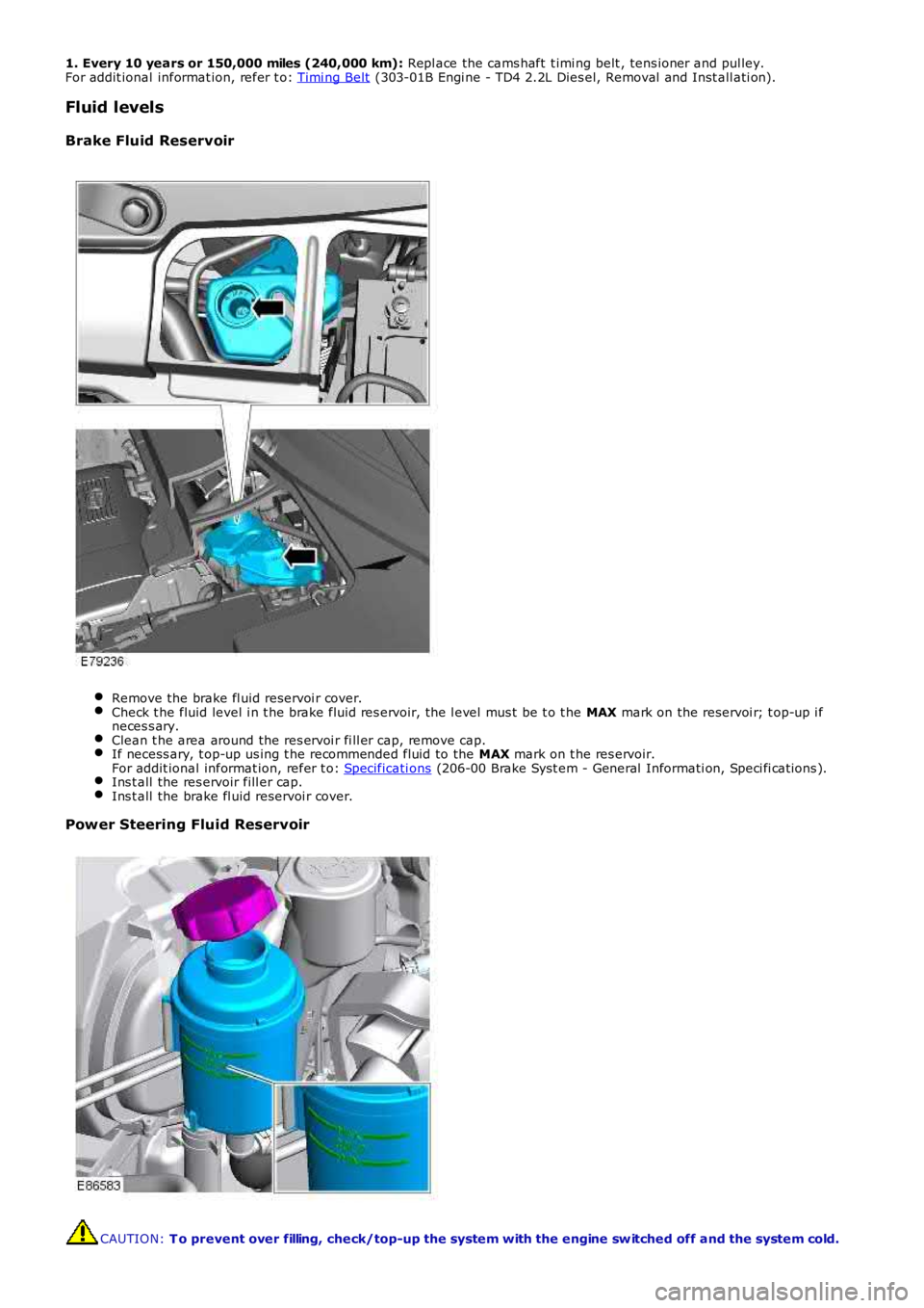
Brake Fluid Reservoir Remove the brake fl uid reservoi r cover.
Check t he fluid level i n t he brake fluid res ervoir, the l evel mus t be t o t he
MAX mark on the reservoi r; t op-up i f
neces s ary. Clean t he area around the res ervoi r fi ll er cap, remove cap.
If necess ary, t op-up us ing t he recommended fluid to the
MAX mark on t he res ervoir.
For addit ional informat ion, refer t o: Specificati ons (206-00 Brake Syst em - General Informati on, Speci fi cat ions ).
Ins t all the res ervoir fill er cap.
Ins t all the brake fl uid reservoi r cover.
Power Steering Fluid Reservoir
CAUTION:
T o prevent over filling, check/top-up the system with the engine sw itched off and th e system cold.
Page 190 of 3229
Ensure that the steering wheel is in the straight ahead position, do not turn the st eering w heel prior to checking the
fluid level.
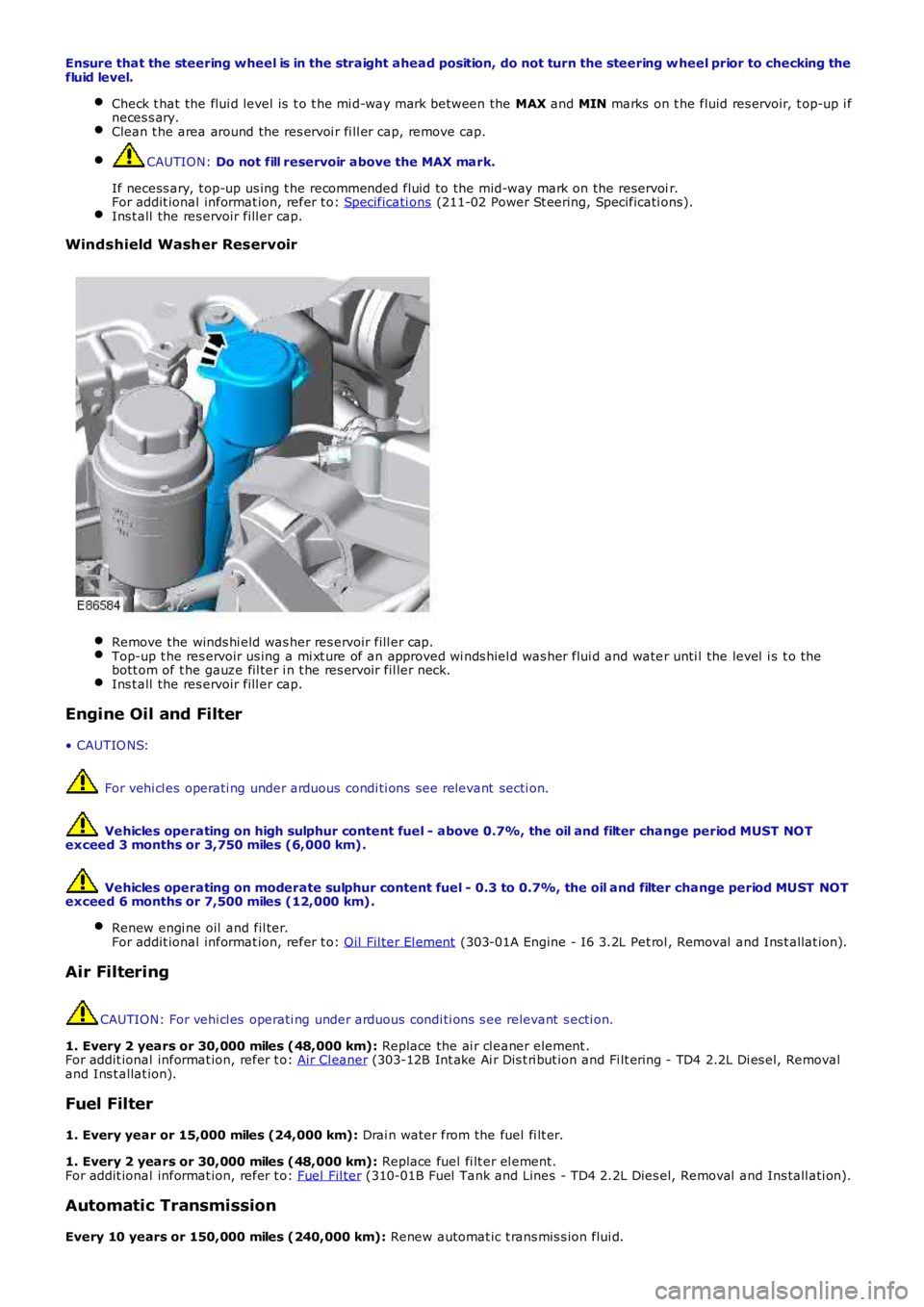
Check t hat the flui d level is t o t he mi d-way mark between the MAX and MIN marks on t he fluid res ervoir, t op-up i f
neces s ary. Clean t he area around the res ervoi r fi ll er cap, remove cap.
CAUTION:
Do not fill reservoir above the MAX mark.
If necess ary, t op-up us ing t he recommended fluid to the mid-way mark on the reservoi r.
For addit ional informat ion, refer t o: Specificati ons (211-02 Power St eering, Specificati ons).
Ins t all the res ervoir fill er cap.
Windshield Washer Reservoir
Remove the winds hi eld was her res ervoir fill er cap.
Top-up t he res ervoir us ing a mi xt ure of an approved wi nds hiel d was her flui d and wate
r unti l the level i s t o the
bott om of t he gauze fil ter i n t he res ervoir fil ler neck. Ins t all the res ervoir fill er cap.
Engine Oil and Filter
• CAUTIO NS: For vehi cl es operati ng under arduous condi ti ons see relevant secti on.
Vehicles operating on high sulphur content fuel - above 0.7%, the oil and filter cha nge period MUST NOT
exceed 3 months or 3,750 miles (6,000 km).
Vehicles operating on moderate sulphur content fuel - 0.3 to 0.7%, the oil and filte r change period MUST NOT
exceed 6 months or 7,500 miles (12,000 km).
Renew engi ne oil and fil ter.
For addit ional informat ion, refer t o: Oil Fil ter El ement (303-01A Engine - I6 3.2L Pet rol , Removal and Ins t allat ion).
Air Filtering
CAUTION: For vehi cl es operati ng under arduous condi ti ons s ee relevant s ecti on.
1. Every 2 years or 30,000 miles (48,000 km): Replace the ai r cl eaner element .
For addit ional informat ion, refer t o: Air Cl eaner (303-12B Int ake Ai r Dis t ri but ion and Fi lt ering - TD4 2.2L Di es el, Removal
and Ins t allat ion).
Fuel Filter
1. Every year or 15,000 miles (24,000 km): Drai n water from the fuel fi lt er.
1. Every 2 years or 30,000 miles (48,000 km): Replace fuel fi lt er el ement.
For addit ional informat ion, refer t o: Fuel Fil ter (310-01B Fuel Tank and Lines - TD4 2.2L Dies el, Removal and Ins tall ati on).
Automatic Transmission
Every 10 years or 150,000 miles (240,000 km): Renew automat ic t rans mis s ion flui d.
Page 192 of 3229
Ins pect rear pads for wear.
Check brake cal ipers for s igns of fl ui d l eaks .
Check brake dis cs for condi ti on.
Check al l brake boos t er and brake s ys t em pipes and hos es for condi ti on, chafi ng and
leaks.Clean road wheel hub s pigot s and appl y greas e, Land Rover Part Number RY L 105020 t o
t he wheel mat ing surface
of each s pigot . Brake Fluid Replacement
CAUTION:
When vehicles are operating under arduous conditions, the following service item mus t be carried out
every 2 Years or 30,000 miles (48,000 km).
Replace brake fluid. Road Wheel Speed Sensors
CAUTION:
When vehicles are operating under arduous conditions, the following service item mus t be carried out
every 3 months or 3,750 miles (6,000 km).
Ins pect the road wheel s peed s ens or harness es for damage. Engine Oil and Filter
• CAUTIO NS:
When vehicles are operating under arduous conditions, the following service item mus t be carried out every 3
months or 3,750 miles (6,000 km).
Vehicles operating on high sulphur content fuel - above 0.7%, the oil and filter cha nge period MUST NOT
exceed 3 months or 3,750 miles (6,000 km).
Vehicles operating on moderate sulphur content fuel - 0.3 to 0.7%, the oil and filte r change period MUST NOT
exceed 6 months or 7,500 miles (12,000 km).
Renew engi ne oil and fil ter. Air Filtering
CAUTION:
When vehicles are operating under arduous conditions, the following service item mus t be carried out
every 12 months or 15,000 miles (24,000 km).
Replace the ai r fi lt er el ement.
For addit ional informat ion, refer t o: Air Cl eaner (303-12A Int ake Ai r Dis t ri but ion and Fi lt ering - I6 3.2L Petrol ,
Removal and Inst all ati on). Accessory Drive Belt
CAUTION:
When vehicles are operating under arduous conditions, the following service item mus t be carried out
every 5 years or 75,000 miles (120,000 km).
Replace the access ory drive bel t. For addi ti onal informat ion, refer to: Acces s ory Drive Belt (303-05A Acces s ory Drive
- I6 3.2L Pet rol, Removal and Ins tal lat ion). Camshaft Timing Belt, Tensioner and Pulley
CAUTION:
When vehicles are operating under arduous conditions, the following service item mus t be carried out
every 4 years or 60,000 miles (96,000 km).
Replace the cams haft t iming belt , tens ioner and pul ley.
For addit ional informat ion, refer t o: Timi ng Belt (303-01B Engi ne - TD4 2.2L Dies el, Removal and Inst all ati on).
Radiator/Charge Air Cooler and Cooling Fan
CAUTION:
When vehicles are operating under arduous conditions, the following items must be ca rried out.
Vis uall y check t he radiat or/charge air cool er for ext ernal obst ruct ions, check cooli ng fan bl ades for damage.Remove any debris from t he charge air cool er us i ng a l ow pres s ure hos e.
Continuous Use In Severe Off-Road Conditions
CAUTION:
After 50 miles (80 km) continuous use in severe off-road conditions i.e. w ading, dee p mud and
abrasive grit/slurry, the following items must be cleaned and inspected.
Page 296 of 3229
programs.
Incorrect Program Usage
Selecti on of an inappropri at e program i s dis couraged in t he followi ng ways:
The act ive program icon is conti nual ly di spl ayed i n t he ins t rument clus ter mes s age centerThe Terrai n Res pons e control modul e 'l ocks ' out cert ain funct ions i n s ome programs, for exampl e:- cruis e control is only avai lable wi th the special programs off or gras s/gravel/s now program- t rans mis s ion 'Sport' mode i s deact ivated i n all s peci al programs .W hen t he i gni ti on has been in t he off mode, cont inuall y for more t han 6 hours , t he Terrai n Respons e s yst emdefault s t o t he special programs off.
Selecti on of an inappropri at e program for the t errain condit ions wil l not endanger the dri ver or cause damage to thevehi cl e. Cont inued us e of an inappropri ate program may reduce t he li fe of s ome component s . The driver may not icereduced vehi cl e res ponse, wi th the engine and t rans mi ss i on bei ng les s respons ive t han in s peci al programs off. Al so, i ns ome programs, HDC wil l remai n on, si gni fi ed by il lumi nat ion of t he HDC indicator in the i nst rument clus t er. The dri ver mayals o not ice t orque 'wi nd-up' i n t he act ive on-demand coupli ng caus ing a braking effect when the vehicl e is manoeuvred i ns ome s peci al programs .
Driver Information
The high-l ine i nst rument clus t er fit t ed to al l vehi cl es wit h Terrain Res pons e, cont ains a mess age center which di spl aysvehi cl e i nformat ion to t he driver. The mes s age cent er contai ns the Terrain Res ponse program icons which dis play t hecurrent ly s elected program. If no s ymbol i s dis played, no special program is sel ect ed and the sys tem is in 'Specialprograms off'.
Any required changes t o t he s ub-s ys t ems are al s o pass ed t o t he dri ver i n t he form of i ndi cat or ill uminat ion i n t heins t rument clus ter or appropriat e mes s ages i n t he mes s age center, 'HDC OFF' for example.
In certai n operati ng condi ti ons , t he Terrai n Res pons e s yst em al s o dis plays advi ce or warning mess ages to ens ure thedri ver i s us ing t he vehi cl e t o it s full potenti al, for example, s t eering angle is dis played i n t he mes sage center t o avoi ddri vi ng in deep rut s wit h s t eering l ock appli ed.
DIAGNOSTICS
The Terrai n Res pons e control modul e s tores informati on on detect ed Terrai n Respons e faul ts and CAN errors whi ch can beint errogat ed usi ng IDS. The Terrain Res ponse s ub-s ys t ems and t he ins trument cl ust er als o s tore informat ion relat ing t oCAN errors from t he Terrain Res pons e control modul e.
The cont rol module al s o s tores the mil es travel ed and ti me el aps ed for t he i ndi vi dual programs which can al so be ret ri evedus ing IDS. Thi s informat ion aids di agnos is of t he Terrain Res pons e s ys tem and als o provi des an indicati on of Terrai nRespons e s yst em abus e by t he dri ver whi ch can l ead to premat ure component failure.
This i nformat ion can al so be us ed to check cus t omer concerns , for exampl e, hi gh fuel cons umpt ion whi ch may be due t ocont inued us e of a cert ain program.
Terrain Response System Fault Diag nosis
Terrai n Res pons e relies on the correct funct ionali ty of t he 4 s ub-s ys tems . If one of the s ub-s ys tems develops a fault , theTerrai n Res pons e s ys tem wil l not funct ion, even though the fault i s NOT in t he Terrain Res pons e s ys tem.
T he T errain Response control module and rotary control should only be investigated if there are no apparent faultsin any of the sub-systems. If a fault in a sub-system is subsequently corrected, the T errain Response system willfunction normally after an ignition mode 1 and 2 (on and off) cycle.
Terrain Response Sub-System Faults
W hen a fault occurs i n a s ub-s yst em, t he dri ver i s alert ed by t he il lumi nat ion of a warning indicator and/or an appropri atemes s age for that s ub-s yst em in t he i ns t rument clus ter mes s age cent er. There wi ll be no warning of a Terrain Res ponses ys t em fault .
W hen a sub-sys t em faul t is present and t he dri ver at tempt s t o s el ect a different Terrain Res pons e program us i ng therot ary control or at t he next ignit ion mode 2 (on) cycl e, a mes sage 'SY STEM FAULT SPECIAL PROGRAMS NOT AVAILABLE'wil l appear in the mess age cent er. This impl ies t hat t he Terrain Res pons e s ys tem has a faul t, but only because asub-system fault is preventing its operation. Thi s mes sage will be di spl ayed for 5 s econds per ignit ion mode 2 cycl e, butis repeat ed i f a further s electi on is made by the driver usi ng t he Terrai n Respons e rot ary control or at t he next ignit ionmode 2 (on) cycle.
• NOTE: The mes s age 'SY STEM FAULT SPECIAL PRO GRAMS NOT AVAILABLE' can al so be generated by a fault i n t he Terrai nRespons e rot ary control or control modul e. Refer to the foll owing i nformat ion for det ail s of rot ary control or control modul efaul ts .
It is not possible for the T errain R esponse control module to cause any fault behavior (w arning indicator illuminationor message generation) in any of the 4 sub-systems. Illuminati on of a s ub-s ys t em warning i ndi cat or and/or as ub-s ys t em relat ed mes sage wi ll NEVER be ass ociated wit h a Terrain Res ponse cont rol module or Terrain Res pons es ys t em fault .
The s ub-s ys t em control modul es can det ect a fault wit h the CAN s ignal from t he Terrai n Res pons e control modul e. If afaul t in t he Terrain Res pons e s ys tem is det ect ed, the s ub-s ys tem cont rol modules wi ll operate in t he 'Special programs off's ett ing. The s ub-s ys t em control modul es wil l record a fault code for a fail ure of t he Terrai n Res pons e CAN si gnal . Thes efaul ts can be retrieved us ing IDS and wi ll provide us eful informat ion t o i ndi cat e i nves ti gat ion of t he Terrain Res pons econt rol module or t he CAN net work.
Terrain Response Rotary Control or Control Module Fault
Page 298 of 3229
Publi s hed: 11-May-2011
Ride and Handling Optimization - Ride and Handling Optimization
Diagnosi s and Tes ti ng
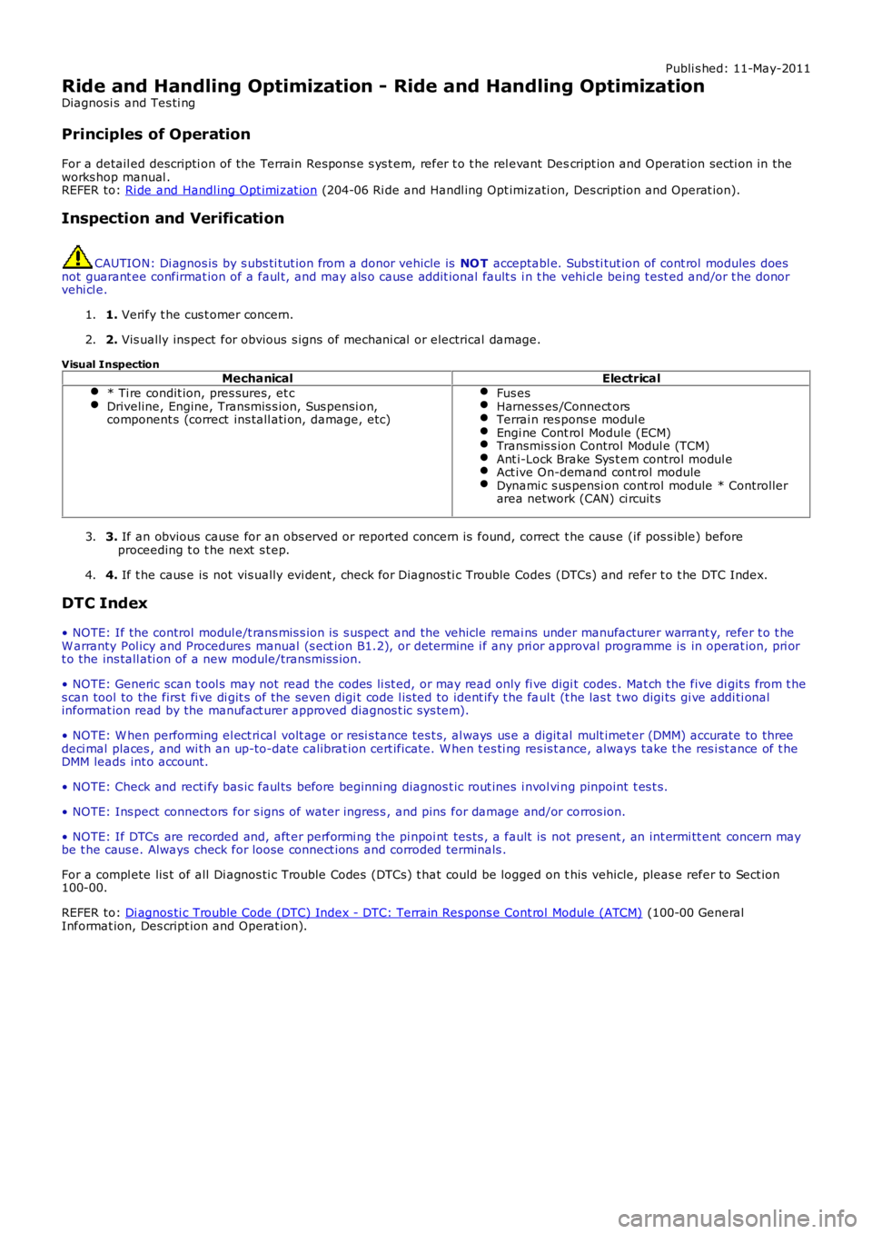
Principles of Operation
For a detail ed descripti on of the Terrain Respons e s ys t em, refer t o t he rel evant Descript ion and Operat ion secti on in theworks hop manual .REFER to: Ri de and Handl ing Opt imi zat ion (204-06 Ri de and Handl ing Opt imizati on, Des cript ion and Operat ion).
Inspection and Verification
CAUTION: Di agnos is by s ubs ti tut ion from a donor vehicle is NO T acceptabl e. Subs ti tut ion of cont rol modules doesnot guarant ee confirmat ion of a faul t, and may als o caus e addit ional fault s i n t he vehi cl e being t est ed and/or t he donorvehi cl e.
1. Verify t he cus t omer concern.1.
2. Vis ually ins pect for obvious s igns of mechani cal or electrical damage.2.
Visual InspectionMechanicalElectrical
* Ti re condit ion, pres sures, et cDriveline, Engine, Transmis s ion, Sus pensi on,component s (correct ins tall ati on, damage, etc)
Fus esHarness es /Connect orsTerrai n res pons e modul eEngi ne Cont rol Module (ECM)Transmis s ion Control Modul e (TCM)Ant i-Lock Brake Sys t em control modul eAct ive On-demand cont rol moduleDynami c s us pensi on cont rol module * Controllerarea network (CAN) ci rcuit s
3. If an obvious cause for an obs erved or report ed concern is found, correct t he caus e (if pos s ible) beforeproceeding t o t he next s t ep.3.
4. If t he caus e is not vis ually evi dent , check for Di agnos ti c Trouble Codes (DTCs) and refer t o t he DTC Index.4.
DTC Index
• NOTE: If the control modul e/t rans mis s ion i s s uspect and the vehicle remai ns under manufacturer warrant y, refer t o t heW arranty Pol icy and Procedures manual (s ect ion B1.2), or determine i f any pri or approval programme is in operat ion, pri ort o the ins tall ati on of a new module/transmis s ion.
• NOTE: Generic scan t ool s may not read the codes li st ed, or may read only fi ve digit codes . Mat ch the five di git s from t hes can tool to the firs t fi ve di git s of the seven digi t code l is ted to ident ify t he faul t (t he las t t wo digi ts gi ve addi ti onalinformat ion read by the manufact urer approved diagnos t ic s ys tem).
• NOTE: W hen performing el ect ri cal volt age or resi s tance tes t s, al ways us e a digit al mult imet er (DMM) accurate to threedeci mal places , and wi th an up-to-date cali brat ion cert ificate. W hen t es ti ng res is t ance, always take t he res i st ance of t heDMM leads int o account.
• NOTE: Check and recti fy bas ic faul ts before beginni ng diagnos t ic rout ines i nvol vi ng pinpoint t es t s.
• NOTE: Ins pect connect ors for s igns of water ingres s , and pins for damage and/or corros ion.
• NOTE: If DTCs are recorded and, aft er performi ng the pi npoi nt tes ts , a fault is not present , an int ermi tt ent concern maybe t he caus e. Always check for loose connect ions and corroded terminals .
For a compl ete lis t of all Di agnos ti c Trouble Codes (DTCs) t hat could be logged on this vehicle, pleas e refer to Sect ion100-00.
REFER to: Di agnos ti c Trouble Code (DTC) Index - DTC: Terrain Res pons e Cont rol Modul e (ATCM) (100-00 GeneralInformat ion, Des cript ion and Operat ion).
Page 300 of 3229
Publi s hed: 11-May-2011
Driveline System - General Information - Driveline System
Diagnosi s and Tes ti ng
Principles of Operation
For a detail ed descripti on of the driveli ne s ys t ems , refer t o t he rel evant Des cript ion and Operat ion s ecti on in the works hopmanual. REFER to:
Dri ves haft (205-01 Driveshaft , Des cript ion and Operat ion),Univers al Joint s (205-01 Dri ves haft , Descripti on and Operat ion),Rear Drive Axle and Different ial (205-02 Rear Drive Axle/Different ial, Des cri pt ion and Operati on),Front Dri ve Axl e and Di fferenti al (205-03 Front Drive Axle/Different ial, Des cript ion and O perati on),Front Dri ve Halfs haft s (205-04 Front Drive Halfs hafts , Des cript ion and Operat ion),Rear Drive Hal fs haft s (205-05 Rear Drive Halfs hafts , Des cript ion and Operat ion).
Inspection and Verification
CAUTION: Di agnos is by s ubs ti tut ion from a donor vehicle is NO T acceptabl e. Subs ti tut ion of cont rol modules doesnot guarant ee confirmat ion of a faul t, and may als o caus e addit ional fault s i n t he vehi cl e being t est ed and/or t he donorvehi cl e.
• NOTE: Cert ain driveli ne s ympt oms are als o common t o t he engine, trans mi s si on, wheel bearings , ti res , and other part sof the vehicle. For thi s reas on, ens ure that t he caus e of t he troubl e is in t he driveline before adjus t ing, repairing, orins t al li ng any new components .
1. Verify t he cus t omer concern.1.
2. Vis ually ins pect for s ys tem int egrit y and obvi ous s igns damage.2.
3. If an obvious cause for an obs erved or report ed concern is found, correct t he caus e (if pos s ible) beforeproceeding t o t he next s t ep3.
4. If t he caus e is not vis ually evi dent , verify t he sympt om and refer t o t he Sympt om Chart, al ternat ively, check forDi agnos ti c Trouble Codes (DTCs) and refer t o t he DTC Index.4.
Identify the Condition
Gear Howl and W hine
Howli ng or whining of t he ring gear and pi nion i s due t o an incorrect gear patt ern, gear damage or i ncorrect beari ngprel oad.
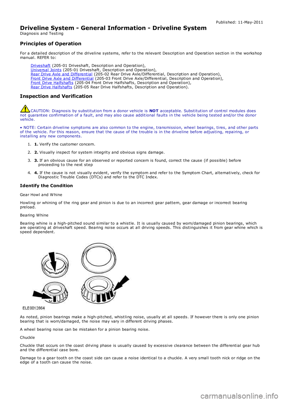
Bearing W hine
Bearing whine i s a high-pi tched s ound si mi lar to a whis t le. It is us ually caus ed by worn/damaged pi nion beari ngs , whichare operat ing at drives haft s peed. Bearing noi se occurs at al l drivi ng speeds . Thi s dis ti ngui s hes i t from gear whine whi ch iss peed dependent .
As noted, pini on bearings make a hi gh-pit ched, whis t li ng noi s e, us ually at al l s peeds . If however t here i s only one pi nionbearing that is worn/damaged, the nois e may vary i n different driving phas es .
A wheel bearing noi se can be mis t aken for a pini on bearing nois e.
Chuckle
Chuckle that occurs on t he coas t dri vi ng phas e is us ual ly caus ed by exces si ve clearance between t he different ial gear huband t he different ial cas e bore.
Damage t o a gear toot h on t he coas t s ide can cause a nois e i dent ical t o a chuckl e. A very s mal l tooth nick or ri dge on theedge of a t oot h can caus e t he nois e.
Page 302 of 3229
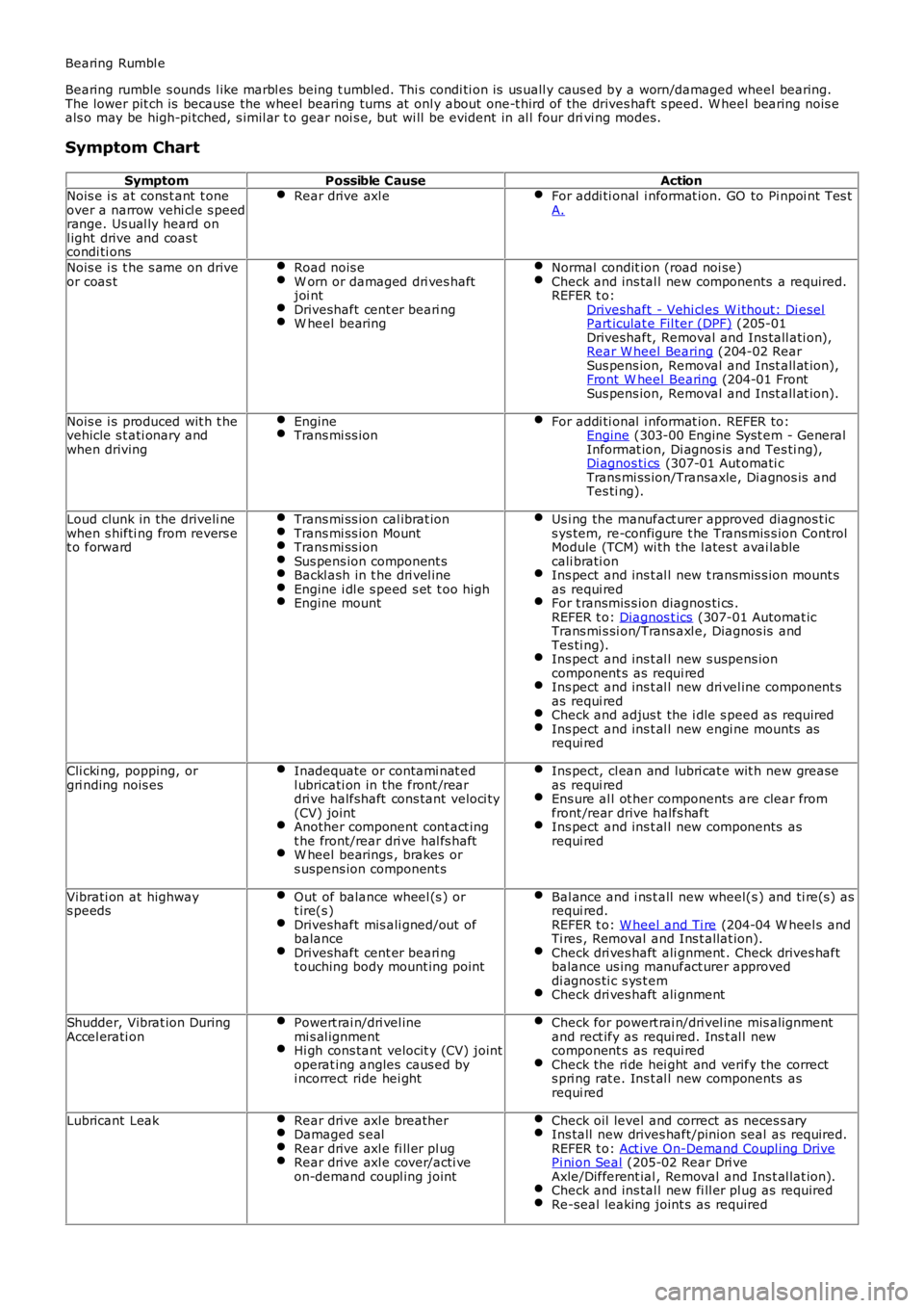
Bearing Rumbl e
Bearing rumble s ounds l ike marbl es being t umbled. Thi s condi ti on is us uall y caus ed by a worn/damaged wheel bearing.The lower pit ch is because the wheel bearing turns at onl y about one-t hird of the drives haft s peed. W heel bearing nois eals o may be high-pi tched, s imil ar t o gear noi s e, but wi ll be evident in al l four drivi ng modes.
Symptom Chart
SymptomPossible CauseActionNois e i s at cons t ant t oneover a narrow vehi cl e s peedrange. Us ual ly heard onl ight drive and coas tcondi ti ons
Rear drive axl eFor addi ti onal i nformat ion. GO to Pi npoi nt Tes tA.
Nois e i s t he s ame on driveor coas tRoad nois eW orn or damaged dri ves haftjoi ntDriveshaft cent er beari ngW heel bearing
Normal condit ion (road noi se)Check and ins tal l new components a required.REFER t o:Driveshaft - Vehi cl es W i thout: Di eselPart iculat e Fil ter (DPF) (205-01Driveshaft, Removal and Ins tall ati on),Rear W heel Bearing (204-02 RearSus pens ion, Removal and Inst all at ion),Front W heel Bearing (204-01 FrontSus pens ion, Removal and Inst all at ion).
Nois e i s produced wit h t hevehicle s t ati onary andwhen driving
EngineTrans mi ss ionFor addi ti onal i nformat ion. REFER to:Engine (303-00 Engine Syst em - GeneralInformat ion, Di agnos is and Tes ti ng),Di agnos ti cs (307-01 Aut omati cTrans mi ss ion/Transaxle, Di agnos is andTes ti ng).
Loud clunk in the driveli newhen s hifti ng from revers et o forward
Trans mi ss ion cal ibrat ionTrans mi ss ion MountTrans mi ss ionSus pens ion component sBackl ash in t he dri vel ineEngine i dl e s peed s et t oo highEngine mount
Us i ng the manufact urer approved diagnos t ics ys tem, re-configure t he Transmis s ion ControlModule (TCM) wi th the l ates t avai lablecali brati onIns pect and ins t al l new t ransmis s ion mount sas requi redFor t ransmis s ion diagnos ti cs .REFER t o: Diagnos t ics (307-01 Automat icTrans mi s si on/Trans axl e, Diagnos is andTes ti ng).Ins pect and ins t al l new s uspens ioncomponent s as requi redIns pect and ins t al l new dri vel ine component sas requi redCheck and adjus t the i dle s peed as requi redIns pect and ins t al l new engi ne mounts asrequi red
Cli cki ng, popping, orgri nding nois esInadequate or contami nat edl ubricati on in the front /reardri ve halfshaft cons tant veloci ty(CV) jointAnother component cont act ingt he front/rear dri ve hal fs haftW heel bearings , brakes ors uspens ion component s
Ins pect, cl ean and lubri cat e wit h new greaseas requi redEns ure al l ot her components are clear fromfront /rear drive halfs haftIns pect and ins t al l new components asrequi red
Vibrati on at highways peedsOut of balance wheel (s ) ort ire(s )Driveshaft mis ali gned/out ofbalanceDriveshaft cent er beari ngt ouching body mount ing point
Bal ance and i ns t all new wheel(s ) and ti re(s) asrequi red.REFER t o: W heel and Ti re (204-04 W heel s andTi res , Removal and Ins t allat ion).Check dri ves haft ali gnment . Check drives haftbalance us ing manufact urer approveddi agnos ti c s ys t emCheck dri ves haft ali gnment
Shudder, Vibrat ion DuringAccel erati onPowert rai n/dri vel inemi s al ignmentHi gh cons tant velocit y (CV) jointoperat ing angles caus ed byi ncorrect ride hei ght
Check for powert rai n/dri vel ine mis alignmentand rect ify as requi red. Ins t al l newcomponent s as requi redCheck the ri de hei ght and verify the corrects pri ng rat e. Ins t al l new components asrequi red
Lubricant LeakRear drive axl e breatherDamaged s ealRear drive axl e fi ll er pl ugRear drive axl e cover/acti veon-demand coupl ing joint
Check oil level and correct as neces s aryIns tall new drives haft/pinion seal as required.REFER t o: Act ive On-Demand Coupl ing DrivePi ni on Seal (205-02 Rear Dri veAxle/Different ial , Removal and Ins t al lat ion).Check and ins tal l new fi ll er pl ug as requiredRe-seal leaking joint s as required