2006 LAND ROVER FRELANDER 2 fuel pressure
[x] Cancel search: fuel pressurePage 32 of 3229
(1) Ride height is measured vertically from wheel center to underside of wheelarch. All figures are with vehicle at'Show room' height - full fluids, full tank of fuel, no occupants/luggage, tires inflated to normal pressures.
(2) 5 seconds maximum duration.
Page 38 of 3229
Flammabl e - OBSERVE NO SMOKING POLICY .
Irrit at ion of t he mout h and t hroat may res ult from s wallowi ng. The main hazard from s wallowi ng ari ses if li qui d as pirat ionint o t he lungs occurs.
Liquid contact dri es the ski n and can caus e i rrit at ion or dermati ti s. Splas hes in the eye may be s light ly i rrit ati ng.
In normal circums t ances t he low vol ati lit y does not give ris e t o harmful vapors . Expos ure to mis t s and vapors fromkeros ene at el evat ed t emperature s houl d be avoi ded (mis ts may ari s e in dewaxing). Avoi d s ki n and eye cont act and makes ure t here i s adequat e vent il ati on.
If sw allow ed, DO NOT induce vomiting - SEEK IMMEDIAT E MEDICAL AT T ENT ION.
Gas Cylinders
Gas es such as oxygen, acet ylene, argon and propane are normall y s tored in cyli nders at pres s ures of up t o 138 bar (13800kPa) (2000 lbf/i n²) and great care should be taken i n handl ing t hese cyli nders t o avoi d mechani cal damage t o t hem or t ot he val ve gear at tached. The contents of each cylinder s houl d be clearl y ident ifi ed by appropri ate markings .
Cylinders should be s tored in wel l vent il at ed encl osures, and protected from ice and s now or direct sunli ght . Fuel gas es,for example acetyl ene and propane should not be st ored i n clos e proximit y t o oxygen cylinders .
Care should be exerci sed to prevent l eaks from gas cyl inders and l ines and als o t o avoid s ources of ignit ion.
Only trai ned pers onnel s houl d undertake work involving gas cyli nders .
General Workshop Tools and Equipment
It is es s ent ial t hat al l tools and equipment are maint ained in good condit ion and t he correct s afet y equi pment is us edwhere required.
Never us e t ools or equipment for any purpos e other t han that for whi ch they were desi gned. Never overl oad equi pments uch as hoi st s , jacks, axle and chas si s s tands or li ft ing sl ings . Damage caus ed by overloading i s not always immediatel yapparent and may res ult i n a fatal fai lure the next t ime that t he equi pment is us ed.
Do not us e damaged or defect ive t ools or equipment, part icularly hi gh s peed equipment s uch as gri ndi ng wheel s . Adamaged grindi ng wheel can dis int egrate wit hout warning and cause serious i njury.
W ear s uit abl e eye prot ect ion when us ing grinding, chis elli ng or s and bl ast ing equi pment .
W ear a s uit able breat hing mas k when us i ng abrasi ve blas ti ng equi pment or us i ng sprayi ng equi pment.
Make s ure t here i s adequat e vent il ati on to cont rol dust s , mis t s and fumes .
High Pressure Air, Lubrication and Oil Test Equipment
Always keep high press ure equi pment i n good condi ti on, and regul arly maint ai ned, parti cularly at joint s and uni ons.
Never di rect a high press ure nozzle, for example dies el i njector, at t he s kin as the fluid may penet rat e t o t he underlyingt is sue and caus e s eri ous i njury.
Jacking
Always refer to the Jacki ng and Lifti ng s ect ion of t hi s manual prior t o rai s ing t he vehi cl e off the ground.
W hen vehicle is t o be rais ed by means of a jack, ensure t hat i t is st andi ng on l evel ground, that parking brake is appli edand wheels are chocked. ALW AY S us e t he recommended jacking poi nt s and ens ure t hat vehi cl e jack has s ufficient loadcapacit y for t he weight of t he vehi cl e.
W ARNING: Do not work on or under a vehi cle s upported onl y by a jack. Always s upport t he vehi cl e on s afet y s tands .
Ensure t hat hois t s have s uffi ci ent load capacit y for t he wei ght of t he vehi cl e.
Legal Aspects
There are many l aws and regulat ions rel at ing to healt h and s afet y i n the us e and di spos al of materials and equipment i n aworks hop.
For a s afe worki ng envi ronment and t o avoi d environment al poll uti on, workshops s hould be famil iar, i n detai l, wi th t hemany healt h and s afety laws and regul ati ons wit hi n t hei r count ry, publ is hed by both nat ional and local aut horit ies .
Lubricants and Greases
Avoi d all prolonged and repeat ed contact wit h mi neral oils . All l ubricants and greases may be irri tat ing t o t he eyes ands ki n.
Used Engine Oil
Prol onged and repeat ed cont act wi th engi ne oil wil l res ult i n t he removal of nat ural fat s from the s kin, leading to drynes s ,irri tat ion and dermati ti s. In addit ion, used engi ne oil cont ains potent iall y harmful cont aminants whi ch may caus e s kincancer. Adequat e means of s kin protecti on and washi ng facil it ies mus t be provi ded.
Do not employ us ed engine oi ls as l ubricants or for any appli cat ion where appreciable s kin cont act i s li kel y t o occur.
Page 647 of 3229
SymptomAction
- Pos it ive readi ngs of bet ween 10-20%: check for air leaks i n air i nt ake s ys t em- Negati ve readings of between 10-20%: check for over fuell ing e.g. leaki ngi njectors , high fuel pres sure- Readings above 20%: check for DTCs and refer t o DTC Index.REFER t o: El ect ronic Engi ne Cont rol s (303-14A El ect roni c Engi ne Cont rol s - I6 3.2LPet rol, Di agnos is and Tes ti ng).Carry out a vacuum gauge check. Refer to component t es ts i n t his s ecti on.
Oi l cons umpti onCarry out oil l eak check fol lowed by an oi l cons umpt ion tes t. Refer t o t he componentt est s i n t hi s s ect ionIf oil cons umpt ion i s exces si ve:Check the integrit y of the engine breat her sys t emCarry out general engi ne checks :- Compress ion tes t. Refer t o component t es ts i n t his s ect ion.- Val ve cl earances .REFER t o: Val ve Clearance Check (303-01A Engine - I6 3.2L Pet rol , GeneralProcedures ).- Spark pl ug condi ti on and col or
Nois eRefer t o t he Speci al Servi ce Mess ages on t he Electroni c Product Q ual it y Report (EPQR)s ys tem for s ound fi les . If t he s ympt om does NOT compare t o any of the s ound files ,contact Deal er Technical Support (DTS).
Component Tests
Engine Oil Leaks
• NOTE: Before ins t al li ng new gasket s or oil s eal s, make sure t hat t he faul t is cl early es t abl is hed.
If the oi l l eak cannot be ident ifi ed clearl y by a vi sual ins pect ion, carry out an Ult raviolet t est :
Fluorescent Oil Additive Method
1. Clean t he engi ne wit h a sui table cl eani ng fl uid (brake cleaner).1.
2. Drai n the engi ne oil and refil l wit h recommended oil , premixed wi th Dies el Engine Oil Dye or equi val ent . Us e aminimum 14.8 ml (0.5 ounce) t o a maxi mum 29.6 ml (1 ounce) of fl uores cent addit ive to all engines. If oil i s notpremixed, fl uorescent addi ti ve mus t fi rs t be added to the crankcas e.
2.
3. Run engi ne for 15 minutes . Stop the engine and i nspect all s eal and gas ket areas for leaks us ing a 12 Vol tMas t er UV Diagnost ic Ins pect ion Ki t or equivalent . A clear bri ght yell ow or orange area wil l i dent ify l eak. Forext remely smal l leaks, s everal hours may be required for t he leak t o appear.
3.
4. As neces s ary, pres surize t he main oil gallery s yst em t o l ocat e leaks due t o incorrect ly sealed, loos e or cockedpl ugs . If the flywheel bol ts l eak oil, l ook for s ealer on t he threads .4.
5. Repai r al l leaks as neces s ary.5.
Compression Test
General Remarks
• NOTE: Removing fuses and di sconnect ing elect rical components may caus e t he Engine Control Modul e (ECM) t o l ogDiagnost ic Troubl e Codes (DTCs ). Aft er t he meas urements have been carried out , DTCs should be cl eared from memory byconnecti ng to the Manufact urer Approved Diagnos t ic Sys tem.
• NOTE: Only check the compress ion pres sure wit h t he valves s et to the pres cri bed clearance (i f thi s can be adjus ted).
The compres si on pres s ure s hould be checked wi th the engine at operat ing temperat ure.
Check the Comp ression Pressure
W ARNING: Move gear s elector lever to 'P' pos i ti on. Fail ure t o follow thi s ins t ructi on may res ult i n pers onal injury.
1. Remove the fuel pump rel ay.1.
2. Start the engine - the engine wi ll s t art, run for a few seconds then s t op.2.
3. Remove the s park pl ugs.3.
4. Ins t al l the compres s ion t es ter.4.
5. Ins t al l an auxi li ary s tarter s wit ch in the st art ing circui t. W it h t he ignit ion swi tch O FF, us ing t he auxi li ary s t arters wi tch, crank the engine a mi ni mum of five compres s ion st rokes and record the hi ghest reading. Not e theapproximat e number of compress i on s trokes requi red t o obt ai n t he highest readi ng.
5.
6. Repeat t he tes t on each cyl inder, cranking t he engine approximat ely t he s ame number of compress i on st rokes .6.
7. Ins t al l the removed components in reverse order, obs erving t he s peci fi ed ti ght ening t orques.7.
8. Clear all DTCs from the ECM.8.
Page 648 of 3229
Interpretation of the Results
• NOTE: Due t o t he poss ibi li ty of l oos e carbon t hat has become t rapped between t he valve face and seat effect ing thepres s ure readi ngs , when carryi ng out a compres s ion t est and cyli nders are found to have low press ures , ins t al l the s parkplugs , road t est t he vehicle and re-t est the s us pect cyl inders . If the correct pressures are rest ored, no further acti on isrequired.
The indicat ed compress i on pres sures are cons idered wi thi n s pecificati on if t he l owest readi ng cyl inder is wi thi n 75% of t hehighest reading.
If the cyli nder pres s ures are found t o be l ow, carry out a l eakdown t est to det ermi ne the locat ion of t he faul t (i f anyleakback can be heard through t he engine breat her sys tem s uspect the pi st on rings , if any leakback can be heard throught he inlet s ys tem sus pect t he i nl et val ve or seat , if any leakback can be heard through the exhaus t mani fold sus pect t heexhaus t val ve or s eat . If t he meas urements for t wo cyl inders next t o each ot her are bot h t oo low then i t is very likely thatt he cyl inder head gas ket bet ween them is burnt t hrough. Thi s can als o be recognized by t races of engi ne oil in the coolantand/or cool ant i n t he engi ne oil ).
Oil Consump tion Test
The amount of oi l an engi ne uses will vary wit h t he way t he vehi cl e is driven i n addit ion t o normal engine-t o-enginevariat ion. This i s es pecial ly t rue during t he fi rs t 16,100 km (10,000 mil es) when a new engine i s bei ng broken i n or unt ilcert ai n i nt ernal components become condit ioned. Vehicles us ed i n heavy-dut y operati on may us e more oil . The fol lowingare exampl es of heavy-duty operat ion:
Trai ler towi ng appl icati onsSevere loading appli cat ionsSust ained high speed operat ion
Engi nes need oi l to lubri cat e t he fol lowing internal component s :
Cylinder block cyl inder wallsPis t ons and pi st on ringsInt ake and exhaus t val ve s temsInt ake and exhaus t val ve guidesAll i nt ernal engi ne component s
W hen t he pis t ons move downward, a t hi n film of oil i s left on the cyli nder wal ls . As t he vehi cl e is operated, s ome oil i sals o drawn int o t he combus t ion chambers pas t the i ntake and exhaus t valve s tem s eal s and burned.
The fol lowing are examples of condi ti ons that can affect oil consumpt ion rates :
Engi ne s izeOperat or driving habit sAmbient t emperaturesQuali ty and vi scos it y of oi lEngi ne is bei ng run in an overfil led condit ion (check t he oil level at least five minutes after a hot s hutdown wi th thevehi cl e parked on a level surface. The oi l level s hould not be above the top of t he cros s-hatched area and t he l et t er"F" i n FULL).
Operat ion under varyi ng condi ti ons can frequent ly be mi sl eadi ng. A vehi cl e t hat has been run for s everal t housand miles ons hort t rips or i n below-freezi ng ambient temperat ures may have cons umed a "normal" amount of oil . However, whenchecking t he engine oil l evel , it may meas ure up to the full mark on t he oil l evel indicator due t o dil uti on (condens ati onand fuel ) in t he engine crankcas e. The vehi cl e t hen might be driven at high s peeds on the hi ghway where t he condens at ionand fuel boil off. The next t ime t he engi ne oil is checked it may appear that a l it er of oi l was us ed i n about 160 km (100mi les ). Oi l cons umpti on rat e is about one l it er per 2,400 km (1,500 mil es).
Make s ure t he s elected engine oi l meets manufact urer s pecificati on and t he recommended API performance cat egory "SG"and SAE vis cos i ty grade as s hown in t he vehicle O wner's Gui de. It is al s o important t hat t he engine oi l i s changed at t heint ervals s peci fi ed for t he t ypi cal operati ng condi ti ons .
The fol lowing di agnos t ic procedure i s us ed to det ermi ne t he s ource of excess i ve oi l cons umpti on.
• NOTE: Oi l us e i s normal ly great er during the first 16,100 km (10,000 mi les ) of servi ce. As mil eage i ncreas es , oil us edecreas es . High s peed dri vi ng, towing, high ambi ent temperat ure and ot her factors may res ult in great er oil use.
1. Defi ne exces si ve cons umpti on, s uch as t he number of miles driven per li ter of oil used. Al so det ermine cust omersdriving habit s , such as s us tai ned hi gh s peed operat ion, t owing, ext ended i dle and other cons iderat ions.1.
2. Verify t hat the engine has no ext ernal oi l leaks as descri bed under Engine Oi l Leaks i n thi s s ect ion.2.
3. Carry out an oil cons umpti on t es t :
Run t he engi ne to normal operati ng t emperature. Swi tch engine OFF and al low oi l to drain back for at l eas tfi ve mi nut es .W i th vehi cl e parked on l evel s urface, check t he engi ne oil l evel.If required, add engine oil t o s et level exactl y t o t he FULL mark.Record t he vehi cl e mi leage.Ins t ruct the cus tomer t o return for a l evel check after driving t he vehi cle as us ual for 1,610 km (1000 mi les ).Check t he oil l evel under t he s ame condit ions and at the same locat ion as the i nit ial check.
3.
• NOTE: If the oi l cons umpti on rat e is unaccept abl e go t o St ep 4.
4. Check t he Posi ti ve Crankcas e Vent ilat ion (PCV) sys t em. Make sure t he s ys t em i s not pl ugged.4.
5. Check for pl ugged oi l drain-back holes i n t he cyl inder head and cyli nder bl ock.5.
6. Carry out a cyl inder compress ion tes t. Refer t o t he Compres s ion Tes t procedure in thi s s ect ion. Thi s can help6.
Page 791 of 3229
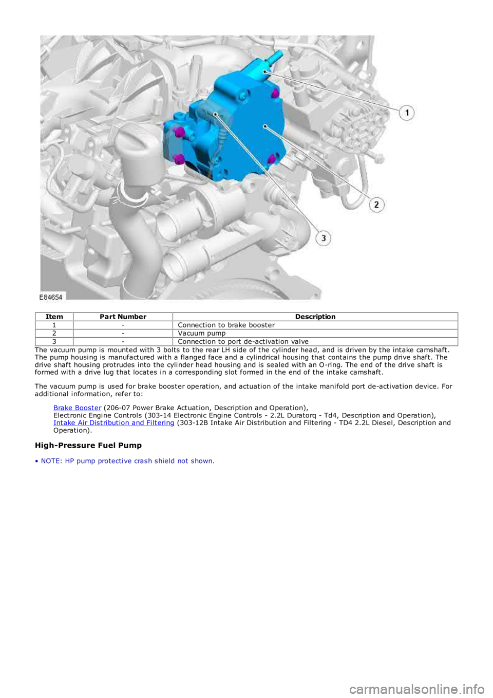
ItemPart NumberDescription
1-Connecti on t o brake boost er2-Vacuum pump
3-Connecti on t o port de-act ivati on val ve
The vacuum pump is mount ed wi th 3 bol ts to the rear LH s ide of t he cyl inder head, and is driven by t he int ake cams haft .The pump housi ng is manufact ured wit h a flanged face and a cyli ndrical hous ing that cont ains t he pump drive s haft . Thedri ve s haft hous ing protrudes into the cyli nder head housi ng and is sealed wit h an O-ri ng. The end of t he dri ve s haft isformed wi th a dri ve lug t hat locat es i n a corresponding s lot formed in t he end of the intake cams haft .
The vacuum pump is us ed for brake boos t er operat ion, and actuati on of the intake mani fold port de-acti vat ion device. Foraddi ti onal i nformat ion, refer to:
Brake Boost er (206-07 Power Brake Act uat ion, Des cript ion and Operat ion),Elect roni c Engi ne Cont rol s (303-14 Electroni c Engi ne Controls - 2.2L Duratorq - Td4, Descri pti on and Operat ion),Int ake Air Dis t ri but ion and Fi lt ering (303-12B Intake Ai r Dis tributi on and Fil tering - TD4 2.2L Dies el, Des cript ion andOperati on).
High-Pressure Fuel Pump
• NOTE: HP pump protecti ve cras h s hield not s hown.
Page 792 of 3229
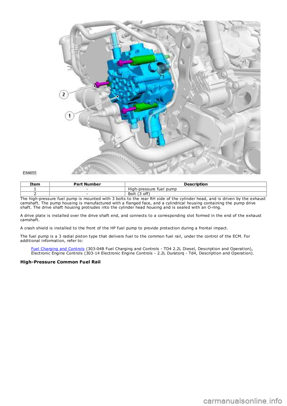
ItemPart NumberDescription
1-High-press ure fuel pump2-Bol t (3 off)
The high-press ure fuel pump i s mounted wi th 3 bolt s t o the rear RH s ide of t he cylinder head, and i s dri ven by the exhaus tcamshaft. The pump hous ing i s manufactured wit h a flanged face, and a cyli ndrical hous ing contai ni ng t he pump dri ves haft. The drive s haft hous ing prot rudes i nt o t he cyl inder head hous ing and i s s ealed wi th an O-ring.
A drive plat e i s ins tal led over the drive s haft end, and connect s t o a corres ponding sl ot formed in the end of t he exhaus tcamshaft.
A cras h s hiel d is ins tal led t o t he front of t he HP fuel pump to provide prot ect ion during a front al impact.
The fuel pump i s a 3 radial pis t on type t hat del ivers fuel t o t he common fuel rail , under the cont rol of the ECM. Foraddi ti onal i nformat ion, refer to:
Fuel Charging and Cont rols (303-04B Fuel Charging and Controls - TD4 2.2L Di es el, Des cri pt ion and Operati on),Elect roni c Engi ne Cont rol s (303-14 Electroni c Engi ne Controls - 2.2L Duratorq - Td4, Descri pti on and Operat ion).
High-Pressure Common Fuel Rail
Page 975 of 3229
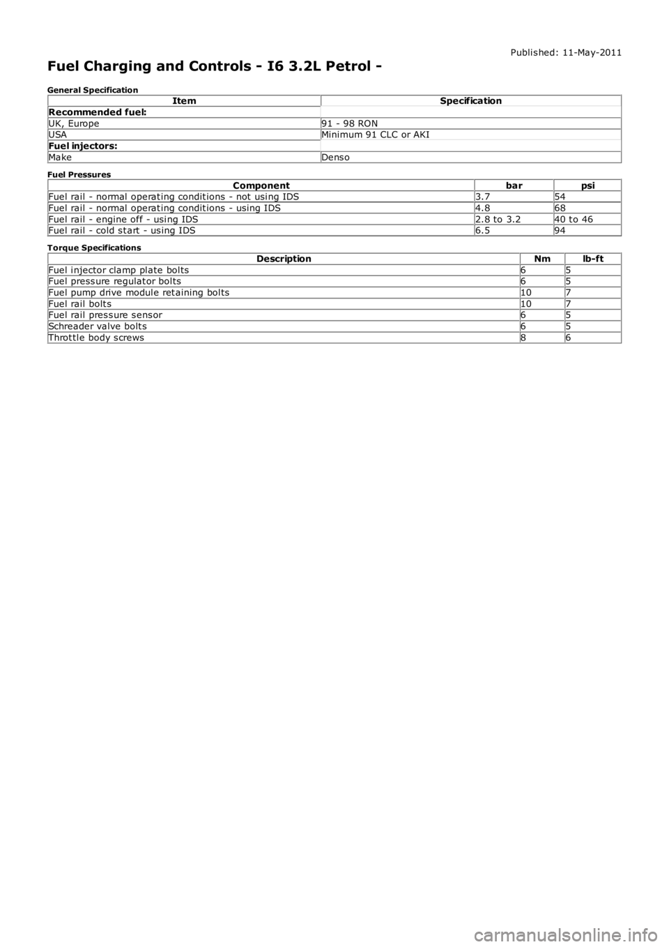
Publi s hed: 11-May-2011
Fuel Charging and Controls - I6 3.2L Petrol -
General SpecificationItemSpecification
Recommended fuel:
UK, Europe91 - 98 RONUSAMinimum 91 CLC or AKI
Fuel injectors:
MakeDens o
Fuel Pressures
ComponentbarpsiFuel rail - normal operat ing condit ions - not usi ng IDS3.754
Fuel rail - normal operat ing condit ions - us ing IDS4.868
Fuel rail - engine off - usi ng IDS2.8 to 3.240 t o 46Fuel rail - cold s t art - us ing IDS6.594
Torque Specifications
DescriptionNmlb-ft
Fuel i njector clamp pl ate bol ts65Fuel press ure regulat or bol ts65
Fuel pump drive modul e ret aining bol ts107
Fuel rail bolt s107Fuel rail pres s ure s ens or65
Schreader valve bolt s65
Throt tl e body s crews86
Page 992 of 3229
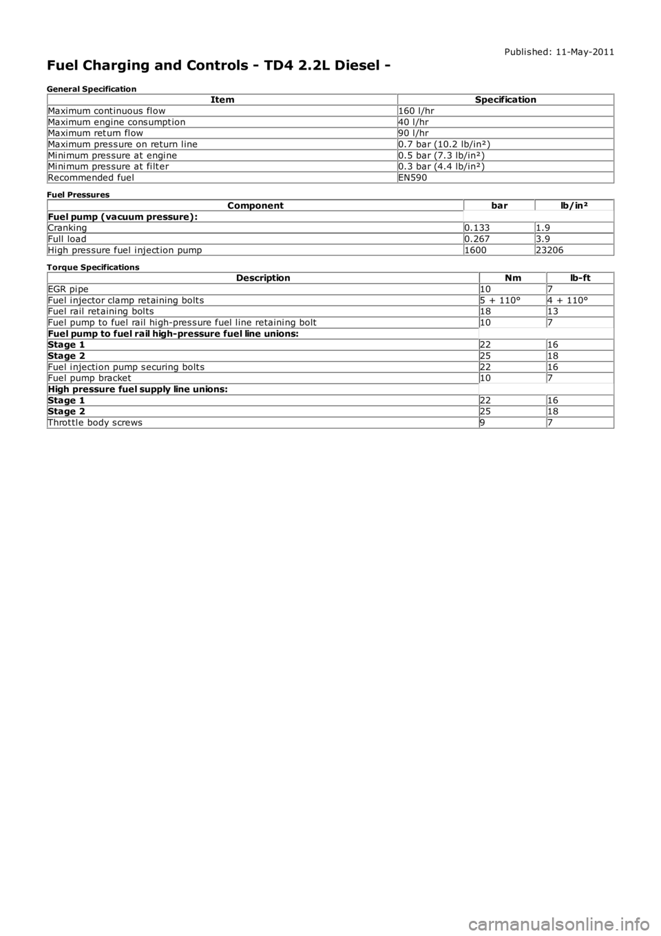
Publi s hed: 11-May-2011
Fuel Charging and Controls - TD4 2.2L Diesel -
General SpecificationItemSpecification
Maximum cont inuous fl ow160 l /hr
Maximum engine cons umpt ion40 l /hrMaximum ret urn fl ow90 l /hr
Maximum pres s ure on return l ine0.7 bar (10.2 lb/in²)
Mi ni mum pres sure at engi ne0.5 bar (7.3 lb/in²)Mi ni mum pres sure at fi lt er0.3 bar (4.4 lb/in²)
Recommended fuelEN590
Fuel Pressures
Componentbarlb/in²
Fuel pump (vacuum pressure):Cranking0.1331.9
Full load0.2673.9
Hi gh pres sure fuel i nject ion pump160023206
Torque SpecificationsDescriptionNmlb-ft
EGR pi pe107
Fuel i njector clamp ret ai ning bolt s5 + 110°4 + 110°Fuel rail ret aini ng bol ts1813
Fuel pump to fuel rail hi gh-pres s ure fuel l ine retaini ng bolt107
Fuel pump to fuel rail high-pressure fuel line unions:Stage 12216
Stage 22518
Fuel i njecti on pump s ecuring bolt s2216Fuel pump bracket107
High pressure fuel supply line unions:
Stage 12216Stage 22518
Throt tl e body s crews97