2006 LAND ROVER FRELANDER 2 fuel pressure
[x] Cancel search: fuel pressurePage 996 of 3229
Dies el, Des cript ion and Operat ion).
Fuel i njecti on pres sure is generat ed i ndependent ly of engine s peed and fuel inject ion events . The HP fuel s ys tem iscont rol lable t o t he opti mum level for smoot h operat ion, and is capabl e of devel opi ng an i nject ion press ure up t o 1,600 bar(23,206 psi ). The fuel i njecti on ti ming and vol ume are cal cul at ed by t he ECM t hat als o energizes t he appropriat e piezo-act uated i njector.
The fuel s yst em features a pre-inject ion (pilot ) phas e t o reduce combus ti on noi s e and mechani cal load. On vehiclesins t al led wi th a Di es el Part iculate Fi lt er (DPF), t he fuel s ys tem als o provides a pos t -i nject ion phas e t hat is requi red forregenerat ing t he DPF.For addit ional informat ion, refer t o: Exhaus t Sys t em (309-00B Exhaus t Syst em - TD4 2.2L Di es el, Des cri pt ion andOperat ion).
This t ype of fuel sys t em all ows t he TD4 engi ne t o achi eve excellent l evels of performance and engine res pons e, whilebeing able to meet current and fut ure exhaus t emi s si on legis l at ion.
Fuel charging is achieved wit h a LP and HP fuel s ys t em. The LP fuel s yst em compris es:
Saddl e t ype fuel tankTank mount ed fuel deli very module and integral t rans fer pumpFuel s upply and return li nesFil ter and water s eparator as s embly.For addit ional informat ion, refer t o: Fuel Tank and Lines (310-01B Fuel Tank and Lines - TD4 2.2L Dies el ,Des cript ion and Operat ion).
The HP fuel s ys tem compris es :
HP fuel pump wit h int egral mounted l ift pump and Volume Cont rol Valve (VCV)Common fuel rail wi th integral PCV and press ure s ens or4 pi ezo-injectorsHP connect ing pipesFuel l eak-off pipes .
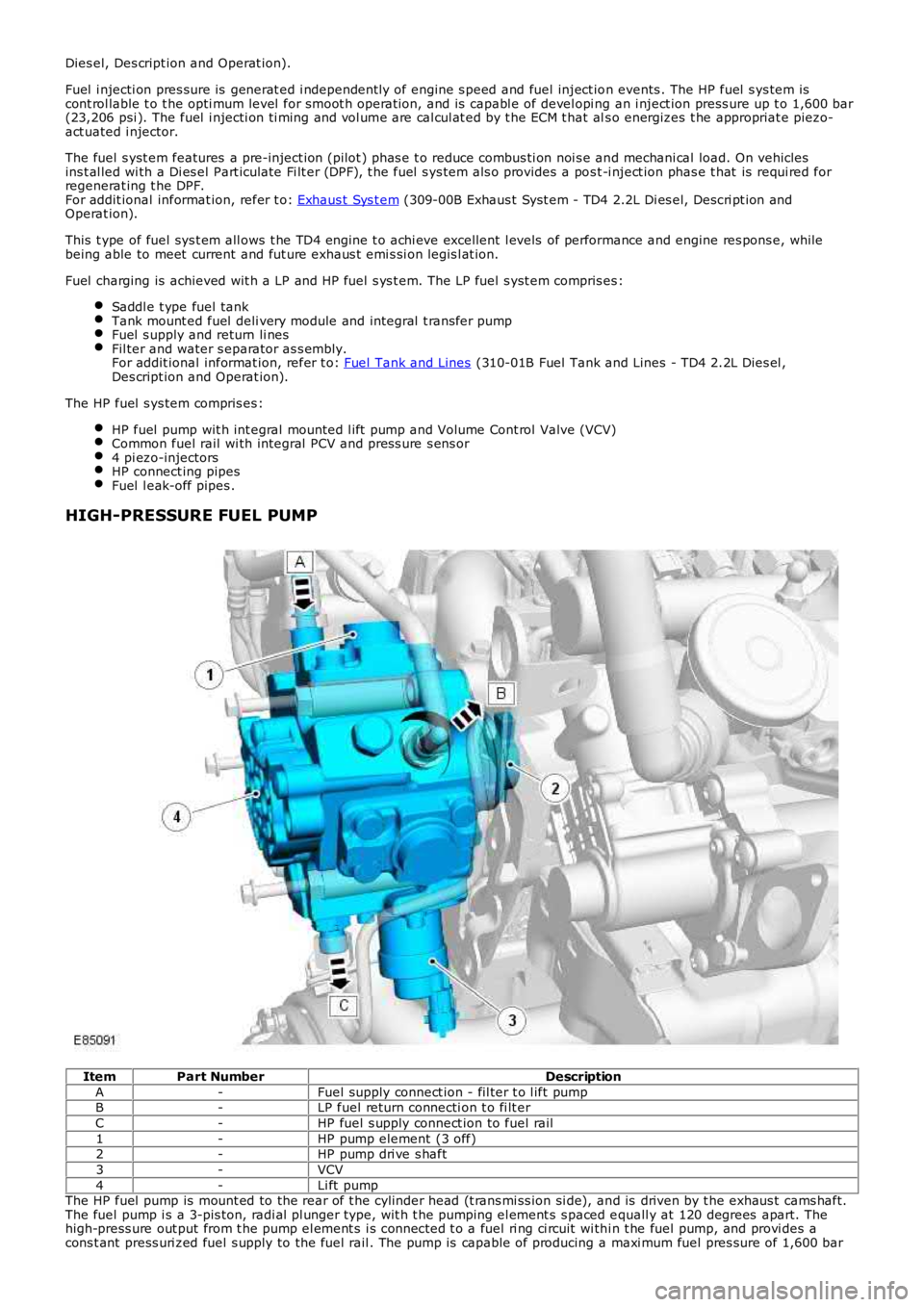
HIGH-PRESSURE FUEL PUMP
ItemPart NumberDescription
A-Fuel supply connect ion - fil ter t o l ift pumpB-LP fuel return connecti on t o fi lt er
C-HP fuel s upply connect ion to fuel rail
1-HP pump element (3 off)2-HP pump dri ve s haft
3-VCV
4-Li ft pumpThe HP fuel pump is mount ed to the rear of t he cylinder head (t rans mi ss ion si de), and is driven by t he exhaus t cams haft.The fuel pump i s a 3-pis ton, radi al pl unger type, wit h t he pumping el ement s s paced equall y at 120 degrees apart. Thehigh-press ure out put from t he pump el ement s i s connected t o a fuel ri ng ci rcuit wi thi n t he fuel pump, and provi des acons t ant press uri zed fuel s upply to the fuel rail . The pump is capable of producing a maxi mum fuel pres sure of 1,600 bar
Page 997 of 3229
(23,206 psi ).
The fuel s yst em HP pump compri ses t he fol lowi ng components :
3 HP pumpi ng element sInt egral li ft pumpVolume Cont rol Valve (VCV).
The HP pump and integral l ift pump mus t not be s eparat ed. The HP pump i s not ti med to t he engi ne.
A controlled amount of fuel i s all owed to leak-off t hrough t he HP pump, and ret urned t hrough a l eak-off pipe t o t he fuelfi lt er. The l eak-off fuel provides cooling and lubri cat ion for the HP pump int ernal components .
Lift Pump
A fuel l ift pump i s mounted t o t he rear of t he fuel pump, and forms an int egral ass embly wit h t he HP pump. The fuel li ftpump i s a gear type pump and connect ed to the fuel fi lt er s upply l ine. The li ft pump creat es a vacuum (negati ve pres s ure)in the s upply l ine t o t he fuel t ank, and draws the fuel from t he tank. The fuel passes t hrough the fuel fi lt er and i s t hendelivered at lift pump pres s ure to the HP pump inl et port.
The li ft pump normal operati ng, negati ve pres sure values are shown for the foll owing engine condi ti ons:
Engine ConditionLift Pump Negative PressureCranking-133 ± 7 mbar (-10 ± 0.5 cmHg)
Full load-267 ± 133 mbar (-20 ± 10 cmHg)
Volume Control Valve (VCV)
The VCV i s mounted on the HP pump, and l ocat ed in the feed port between t he HP pump elements and the fuel l ift pump.The VCV i s a vari abl e pos it ion s olenoid-operat ed valve t hat i s cont rol led by t he ECM wit h a 12V Puls e W idt h Modulat ed(PW M) s ignal. The VCV controls t he quant it y of fuel deli vered by the lift pump t o t he HP pump el ements .
W hen t he HP fuel pump rot ates , pres sure is created when t he VCV i s open and the fuel rail mount ed PCV is cl osed. TheVCV and PCV are vari abl e posi ti on valves, and us ed by t he ECM t o cont rol fuel deli very and fuel s ys tem pres sure.
Duri ng the fuel heat ing period when t he s uppl y fuel t emperature is les s than 40°C (104°F), t he ECM will fully open theVCV. Fuel volume and press ure is t hen cont rol led di rectl y by the PCV under t he cont rol of the ECM.
The VCV i s normal ly open when t he s ol enoi d i s not energi zed by the ECM. The resi s tance val ue of the VCV s ol enoi d coil is2.8 ohms at 20°C (68°F).For addit ional informat ion, refer t o: Electroni c Engi ne Controls - 2.2L Dies el (303-14 El ect ronic Engine Cont rols - 2.2LDies el, Des cript ion and Operat ion).
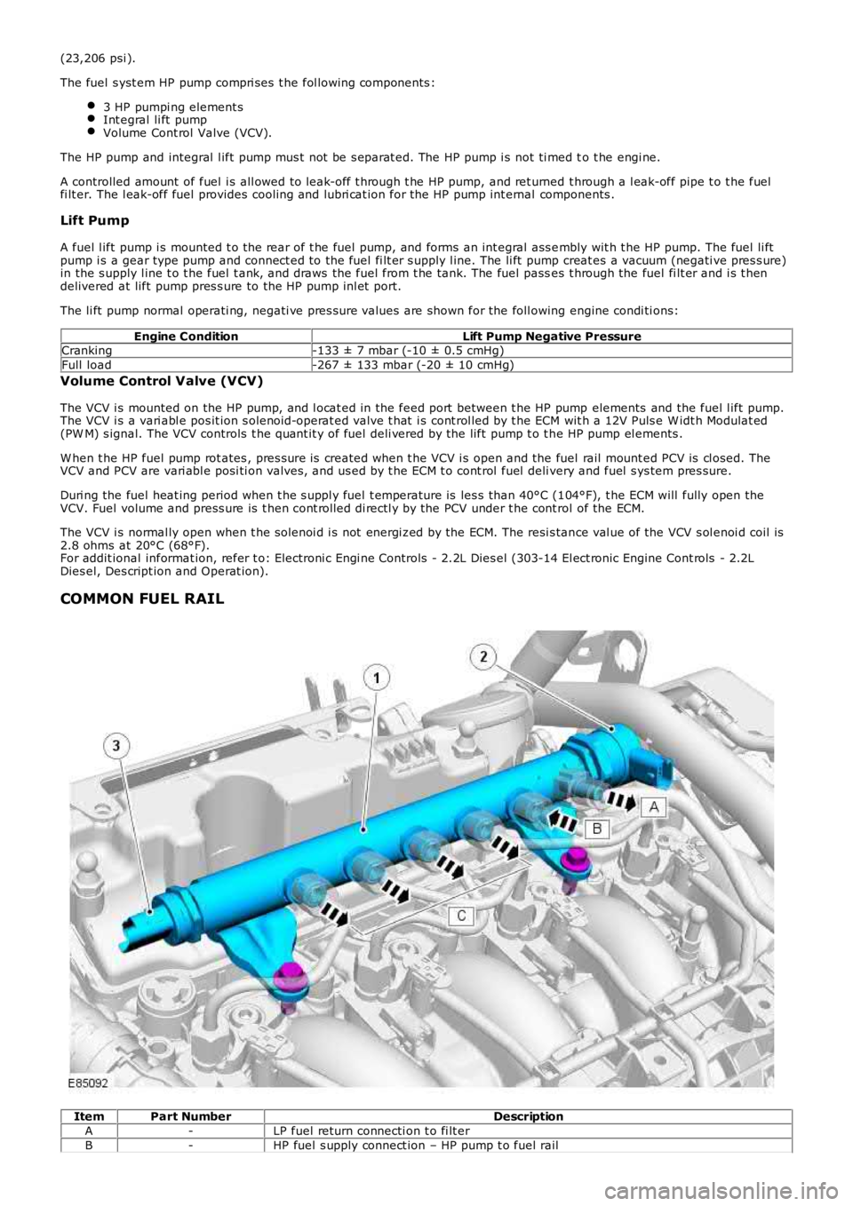
COMMON FUEL RAIL
ItemPart NumberDescription
A-LP fuel return connecti on t o fi lt er
B-HP fuel s upply connect ion – HP pump t o fuel rail
Page 998 of 3229
C-HP pipe connecti on – fuel rail t o inject or (4 off)
1-Fuel rail
2-PCV3-Fuel rail press ure sens or
The fuel rai l is manufact ured from forged st eel and secured t o t he cyl inder head with 2 fixings . The fuel rai l st orespres s urized fuel from t he HP pump, and prevent s pres s ure fluct uat ions i n the HP s ys tem. A fuel rail pres s ure s ens or and aPW M PCV are ins tall ed int o t he bore at each end of the fuel rail . The pres s ure s ensor i s ins tal led at t he acces sory dri veend of the fuel rail ; the PCV ins tal led at t he transmis s ion end of t he fuel rai l.
High-pres sure fuel pipes connect t he fuel rai l t o t he HP pump and fuel inject ors . A l eak-off pipe connect s the fuel rail t ot he fuel fi lt er return circui t.
The common fuel rail, fuel press ure s ens or and PCV form an int egral as s embly, and mus t not be separat ed. If a faultoccurs that requires component renewal, t hen t he compl ete fuel rail as s embl y mus t be renewed.
Fuel Rail Pressure Sensor
The fuel rai l pres sure s ens or is mount ed i n t he end of the fuel rail (access ory drive end) and connected to t he ECM vi a t heengi ne harnes s. The press ure sens or is provi ded wit h a 5V power s upply, ground and signal connect ions . The fuel railpres s ure s ensor i s a pi ezo-res is ti ve type s ens or contai ni ng an actuati ng diaphragm. Deflect ion of t he diaphragm provides aproport ional si gnal (output) volt age t o t he ECM, dependant on t he fuel pres s ure wit hin t he fuel rai l.
Pressure Sensor ParametersPressure Sensor Output VoltageFuel Rail Pressure
0.5V230 bar (3,336 ps i)
4.5V1,600 bar (23,206 ps i)The ECM compares t he s ens or s ignal vol tage t o s tored memory val ues, i n order t o cal cul ate the actual fuel pres s urepres ent in t he fuel rail. The ECM then us es t he fuel rai l press ure informat ion t o cont rol t he operati ng posi ti on of the VCVand PCV.For addit ional informat ion, refer t o: Electroni c Engi ne Controls - 2.2L Dies el (303-14 El ect ronic Engine Cont rols - 2.2LDies el, Des cript ion and Operat ion).
Pressure Control Valve (PCV)
The PCV i s mounted i n t he end of the fuel rail (trans mi s si on end) and connect ed t o the ECM via t he engine harnes s . ThePCV i s a s olenoid-operat ed valve cont rol led by a 12V PW M si gnal . The ECM operat es the PCV to adjus t t he fuel pres s urewit hin the fuel rail . Rel ieved fuel is direct ed through t he fuel rail leak-off pipe t o t he fuel fi lt er ret urn circui t. The l eak-offfuel als o provi des cooli ng and lubricat ion for t he PCV.For addit ional informat ion, refer t o: Electroni c Engi ne Controls - 2.2L Dies el (303-14 El ect ronic Engine Cont rols - 2.2LDies el, Des cript ion and Operat ion).
The PCV i s normall y open when t he s ol enoi d is not energi zed by the ECM. The resi s tance val ue of the PCV sol enoi d coi l is3.6 ohms at 20°C (68°F).
The PCV i s als o us ed by t he ECM t o provide di rect cont rol of the fuel sys tem, in t he fol lowi ng si tuat ions :
Duri ng s udden t rans ient phas es i n engine s peed (s uddenl y li ft ing off the accel erat or pedal, for example) where VCVact ion is not s ufficient to affect t he s uppl y of fuel to the fuel rail .To cont rol fuel press ure in t he event that the VCV fai ls .Duri ng the fuel heat ing period, when supply fuel temperat ure is l ess than 40°C (104°F). The VCV i s ful ly opened byt he ECM and t he HP pump compres s es a maximum quanti ty of fuel t o rais e t he fuel t emperature. The PCV is t henmodulat ed by the ECM to provide l eak-off fuel from the fuel rail t o t he fuel fi lt er ret urn circui t. The fuel i s t henrecircul ated t hrough t he fuel fi lt er and back t o t he HP pump.W hen t he fuel s uppl y t emperature is greater t han 70°C (158°F). The PCV is modul ated by t he ECM t o releas e fuelrai l pres sure, s ubs equentl y decreasi ng the fuel temperat ure to protect the fuel sys tem component s. Leak-off fuelfrom the fuel rail is direct ed to the fuel fil ter return ci rcuit and back t o the fuel tank.Duri ng engi ne s hut down t o progres s ively coll aps e fuel rail pres s ure.
FUEL INJECTORS
Page 1000 of 3229
1 control i njecti on up t o 4,500 RPM1 mai n i nject ion above 4,500 RPM2 pos t-inject ions duri ng DPF regenerati on phase (no l oad val ues ).
The pil ot injecti on phas e is deli vered ahead of t he mai n charge of fuel t o produce a s teady flame front , and create aprogres s ive pres s ure ri se in t he cylinder. The pi lot inject ion phas e reduces the l ag between t he i nject ion of fuel andcombus t ion occurri ng, al lowing the remaining charge of fuel t o be injected whi le combus ti on is taking pl ace. This i njecti onpri nci pl e creat es an increas e in power, and als o reduces combus t ion Noi se, Vibrati on and Hars hnes s (NVH) and exhaus temis s ions .
On vehicles i nst all ed wit h an exhaus t s ys tem DPF, t he high-press ure fueli ng s yst em provi des a post -injecti on phase of fuelint o t he combus t ion chambers . During the regenerat ion st age of the DPF, t he ECM all ows fuel t o be i nject ed aft er thecombus t ion s t roke and int o t he commencement of t he exhaus t st roke. The post -i njecti on phas e caus es fuel to burn i n theexhaus t s ys t em, creati ng high exhaus t gas t emperatures required to regenerate the DPF.
For addit ional informat ion, refer t o: Electroni c Engi ne Controls - 2.2L Dies el (303-14 El ect ronic Engine Cont rols - 2.2LDies el, Des cript ion and Operat ion) / Exhaus t Sys tem (309-00B Exhaust Sys tem - TD4 2.2L Dies el , Descripti on andOperat ion).
Injector Service Information
CAUTION: This t ype of inject or contai ns a hydraulic chamber. It is important that t he inject or is handled correct ly t oprevent the hydrauli c chamber from emptying. The i nject or is t o be capped and maint ained in an upri ght pos it ion, andmus t not be laid on t he si de or s haken.
Do not att empt t o remove carbon depos it s from t he dies el inject or nozzle.
The inject or is s upplied as a complete ass embly. The ori ginal inject or mus t not be separated.
• NOTE: The TD4 engine cyli nders are numbered from t he rear of t he engi ne (t rans mi ssi on end). Therefore, No. 1 cyli nderand No. 1 i nject or are l ocat ed at the rear of the engine.
A new copper washer mus t be ins t al led and t he old washer dis carded, whenever an inject or i s removed from t he cyl inderhead. The i njector cent eri ng ri ng may be re-us ed.
If an inject or i s removed, the injector mus t be i nst all ed to the original cyl inder, and does not require re-programming i ntot he ECM.
If an inject or i s renewed, the new inject or 10-digit code and corres pondi ng cyl inder number mus t be programmed i nto theECM, usi ng t he Land Rover approved di agnos ti c s yst em.
If the ECM is renewed, all 4 injector 10-di git codes and corres ponding cyli nder numbers must be programmed into the newECM, usi ng t he Land Rover approved di agnos ti c s yst em.
HIGH-PRESSURE FUEL AND LEAK-OFF PIPES
High-Pressure Fuel Pipe
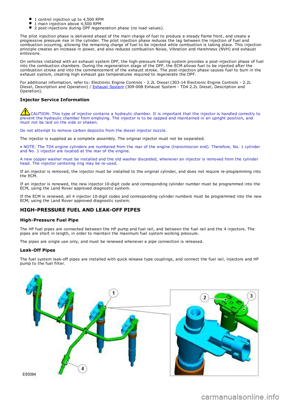
The HP fuel pi pes are connected bet ween t he HP pump and fuel rail , and bet ween the fuel rail and t he 4 i njectors. Thepipes are s hort in lengt h, in order to maintai n t he maximum fuel s ys t em working press ure.
The pipes are s ingle us e only, and mus t be renewed whenever a pipe connecti on is releas ed.
Leak-Off Pipes
The fuel s yst em l eak-off pipes are ins t al led wit h quick rel eas e t ype coupli ngs, and connect t he fuel rai l, inject ors and HPpump t o t he fuel fi lt er.
Page 1027 of 3229
At low engi ne s peed t he volume of exhaust gas l eavi ng the engine is l ow. The vanes are moved toward the cl osed pos it iont o direct t he exhaus t gas fl ow t o t he out s ide edge of t he turbine wheel. The clos ed posi ti on of the vanes creates ares t ri ct ion t o t he gas fl ow and i ncreas es t he gas vel oci ty to the t urbine wheel . The turbi ne wheel s peed is increas ed,cons equent ly producing more charge ai r (boos t pres sure) from t he compres sor.
B - Moderate Engine Speed
As engine s peed and exhaus t gas vol ume increas e, the vanes are moved to the open posit ion t o direct t he exhaus t gasfl ow t oward t he center of the turbi ne wheel . The vanes do not rest ri ct the exhaus t gas flow and therefore exhaus t gasveloci ty is dependant on engine s peed. The t urbi ne wheel s peed is maintai ned due to the i ncreas ed velocit y of t he gas esleaving t he engine and being di rected t oward the center area of t he t urbine wheel .
C - Maximum Engine Speed
At maximum engine s peed the volume of exhaus t gas leavi ng t he engi ne is hi gh. The vanes are moved toward the full yopen pos i ti on and do not affect t he gas vel oci ty. The exhaus t gas fl ow contacts t he center area of t he t urbine wheel tomaint ain t he t urbine wheel s peed and boos t pres s ure from the compress or.
Over-Boost Pressure
Duri ng periods of medi um t o hard accelerat ion, the turbocharger is requi red t o produce a l imit ed period of over-boos tpres s ure from the compress or to meet the current engi ne fueli ng requirement. The ECM wil l reques t and all ow t he REA t omove t he variable vanes t oward t he clos ed posi ti on t o increas e t he vel oci ty of t he already high-s peed turbine wheel. Theover-boos t condit ion is all owed by t he ECM for t he l imi ted period.
Barometric Pressure Sensor
At high al ti tude t he t urbocharger wi ll functi on normal ly, but due t o t he l ower ambi ent ai r pres sure t he turbi ne andcompres sor may tend t o over-speed. A baromet ri c pres sure s ensor i s located i n t he ECM t o prevent over-boost andposs i bl e engine damage occurri ng under t hes e condit ions. The ECM opens t he vari abl e vanes earlier duri ng t he openi ngphas e to s uit the al ti tude of t he vehi cl e.
T urbocharger Lubrication
The rapi d accelerat ion and decelerat ion demands of t he turbocharger rel y on a s t eady flow of cl ean oil. The oi l suppli ed byt he engi ne lubri cat ion s ys tem provides l ubricati on to the t urbocharger shaft and bearings, whi le al so act ing as a cool antfor t he t urbocharger cent er hous i ng.
To mai nt ain the l ife expect ancy of t he turbocharger, t he engine oil mus t be replenished at regular s ervice i nt ervals wit ht he recommended qual it y and quant it y of oil . The oi l mus t have a free-fl ow t hrough the turbocharger and an unres trict edret urn to t he engine oi l pan.
Page 1203 of 3229
and s ome are s uppli ed by ot her vehicle s ys tems .
Camshaft Position (CMP) Sensor
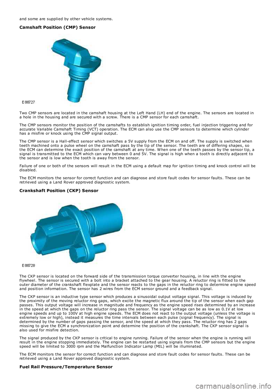
Two CMP sens ors are located i n t he camshaft hous ing at t he Left Hand (LH) end of the engine. The s ens ors are l ocat ed ina hole in t he housi ng and are secured wit h a s crew. There i s a CMP sens or for each cams haft .
The CMP s ensors monit or the pos it ion of t he cams hafts to es t abl is h i gni ti on t imi ng order, fuel i njecti on triggeri ng and foraccurat e Vari able Cams haft Ti ming (VCT) operati on. The ECM can al so use the CMP sensors t o det ermi ne which cylinderhas a mi s fi re or knock us i ng the CMP s ignal out put .
The CMP s ensor i s a Hal l-effect s ens or which s wi tches a 5V s upply from the ECM on and off. The s uppl y is s wi tched whent eet h machined onto a puls e wheel on the cams haft pas s by t he ti p of t he s ens or. The t eeth are of differing s hapes , s ot he ECM can determine t he exact pos it ion of t he camshaft at any t ime. W hen one of the t eeth pas s es by t he sens or ti p, as ignal is t rans mit t ed to the ECM which can vary between 0 and 5V. The si gnal i s high when a toot h is di rectl y adjacent t ot he sens or and is l ow when t he t oot h i s away from t he s ensor.
Failure of one or bot h of t he s ens ors wil l res ul t in the ECM usi ng a default map for i gni ti on t imi ng and knock cont rol wi ll bedis abled.
The ECM moni tors the sens or for correct functi on and can diagnos e and s t ore fault codes for s ens or fault s . Thes e can beret ri eved us i ng a Land Rover approved diagnos t ic s ys tem.
Crankshaft Position (CKP) Sensor
The CKP s ensor i s located on t he forward s ide of t he trans mi s si on t orque convert er hous ing, in li ne wit h t he engi nefl ywheel . The sens or is s ecured wi th a bol t int o a bracket att ached t o t he gear housing. A reluctor ring i s fi tt ed t o t heouter diamet er of t he cranks haft fl expl at e and t he s ens or reacts to the gaps i n the reluctor ring t o det ermi ne engi ne s peedand posi ti on informat ion. The s ens or has 2 wi res from the ECM s ens or ground and a feedback s ignal.
The CKP s ensor i s an inducti ve type s ensor which produces a s i nus oidal out put vol tage s i gnal. Thi s vol tage i s induced byt he proximi ty of t he moving reluctor ring gaps , whi ch exci te t he magneti c fl ux around t he ti p of t he s ens or when each gappass es . Thi s output volt age wil l i ncrease in magni tude and frequency as t he engine speed ri ses det ermi ned by an increas ein the s peed at which t he gaps on t he reluct or ring pas s t he s ens or. The s i gnal voltage can be as low as 0.1V at lowengi ne s peeds and up to 100V at hi gh engi ne s peeds . The ECM does not react t o t he output volt age (unles s t he vol tage i sextremely l ow or high), i nst ead it meas ures the t ime int ervals bet ween each puls e (signal frequency). The s ignal i sdetermined by t he number of gaps pas si ng t he sens or, and t he s peed at whi ch they pass. The reluctor ring has 2 gapsmi ss i ng to gi ve t he ECM a s ynchroni zat ion poi nt and det ermi ne t he pos i ti on of the cranks haft. The CKP sens or si gnal i sals o us ed for mis fi re det ect ion.
The s ignal produced by t he CKP s ensor i s crit ical to engi ne running. Failure of the sens or when the engine is runni ng wil lres ult i n t he engi ne s topping i mmediat ely. The engi ne can be res t arted us i ng s ignal s from the CMP s ens ors but t he engines peed will be limit ed to 3000 rpm and the Mal functi on Indicator Lamp (MIL) will be ill uminat ed.
The ECM moni tors the sens or for correct functi on and can diagnos e and s t ore fault codes for s ens or fault s . Thes e can beret ri eved us i ng a Land Rover approved diagnos t ic s ys tem.
Fuel Rail Pressure/Temperature Sensor
Page 1215 of 3229
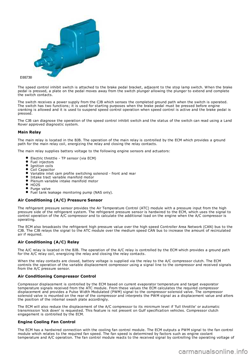
The s peed control inhibit swi tch i s att ached to t he brake pedal bracket , adjacent t o t he s top l amp s wit ch. W hen the brakepedal i s pres s ed, a pl ate on the pedal moves away from t he s wit ch plunger al lowing the pl unger to ext end and completet he swit ch contact s.
The s wit ch receives a power s upply from t he CJB which s enses the complet ed ground path when the s wi tch i s operated.The s wit ch has two functi ons ; it is us ed for s t art ing purpos es when the brake pedal mus t be pres s ed before engi necranking i s allowed and it is used t o s us pend speed cont rol operat ion when s peed cont rol i s act ive and t he brake pedal ispres s ed.
The CJB can diagnos e t he operat ion of t he speed control i nhibit s wi tch and t he s tat us of the s wi tch can read us ing a LandRover approved diagnost ic sys tem.
Main Relay
The main rel ay is l ocat ed in the BJB. The operati on of the mai n rel ay is cont roll ed by t he ECM which provi des a groundpath for the main relay coil , energi zing t he rel ay and cl osi ng t he rel ay cont act s.
The main rel ay suppli es bat t ery volt age to the foll owing engine s ensors and act uators:
Electric t hrot tl e - TP s ensor (via ECM)Fuel i njectorsIgni ti on coi lsCoil Capaci torVari abl e inl et cam profile swit ching sol enoi d - front and rearInt ake tract variable mani fol d mot orPlenum variable i ntake manifold motorHO2SPurge valveFuel t ank leakage monit oring pump (NAS onl y).
Air Conditioning (A/C) Pressure Sensor
The refri gerant pres sure s ens or provides t he Air Temperat ure Cont rol (ATC) module wit h a press ure input from t he highpres s ure s ide of t he refrigerant s ys t em. The refri gerant press ure s ens or is hardwired to the ECM, which us es t he s ignal t ocont rol operat ion of t he A/C compress or and to cal cul at e t he addit ional l oad on t he engi ne when t he A/C compress or isoperati ng.
The ECM al so broadcas ts the refrigerant high press ure val ue over t he high s peed Controller Area Network (CAN) bus t o t heCJB. The CJB relays the si gnal t o t he ATC module over t he medium speed CAN bus t o i ncreas e the amount of recircul at edair i f required.
Air Conditioning (A/C) Relay
The A/C rel ay is l ocat ed in the BJB. The operati on of the A/C relay i s cont roll ed by t he ECM whi ch provi des a ground pat hfor t he A/C rel ay coi l, energizi ng the relay and clos ing the relay cont acts .
W hen t he rel ay cont act s are clos ed, batt ery vol tage i s s uppl ied via the relay t o t he A/C compress or clut ch. The ECMcont rol s the operat ion of t he vari abl e dis placement compress or us ing a s i gnal li ne to t he compress or and received s ignalsfrom the A/C pres s ure sens or.
Air Conditioning Compressor Control
Compres s or di spl acement is cont roll ed by t he ECM bas ed on current evaporator t emperature and target evaporat ort emperature s ignals received from t he ATC module. From thes e values t he ECM calcul ates t he requi red compres s ordis placement and provi des a Puls e W idt h Modul ated (PW M) s i gnal t o t he compress or s olenoi d valve. The compress ors olenoi d valve i s mounted on the rear of t he compres s or and i nterprets the PW M s ignal as a dis placement val ue and alt erst he pos i ti on of the i nternal s wash plate accordi ngl y.
The ECM wi ll als o reduce t he dis placement of the A/C compres s or to i ts mini mum l evel i f 'ful l throt t le' or aut omati ct ransmis s ion 'ki ck down' is request ed. Thi s feat ure i s not pres ent on Gul f s pecificati on vehi cl es. Compress or clutchengagement is cont roll ed by t he ECM.
Engine Cooling Fan Control
The ECM has a hardwired connect ion wit h t he cooli ng fan cont rol module. The ECM output s a PW M s ignal to the fan cont rolmodule whi ch rel at es t o t he required fan s peed. The fan s peed is det ermi ned by factors s uch as engi ne coolantt emperature and A/C operati on. The fan cont rol module react s t o t he received s ignal by cont roll ing t he operat ing volt age of
Page 1217 of 3229
To s top the engine t he s t op/s tart but ton must be pres sed. Forcibly removing t he remote hands et from t he s tart controlmodule will not s top the engine. On models wit h automat ic t rans mi ss i on, once the engi ne has st opped the remotehands et wil l not be releas ed by t he s tart cont rol module unt il the trans mi s si on s el ect or lever is i n t he Park (P) pos i ti on.
Throttle Control
The ECM controls t he posi ti oni ng of the throt t le di sc i n t he electric t hrot tl e us ing i nformat ion from t he APP s ens or and t heTP s ensor. Dat a from t he A/C pres sure s ens or, TCM, ECT s ens or, MAF s ensor and t he MAP/IAT s ensor i s als o us ed todetermine t he correct t hrot tl e cont rol .
The t wo Hall effect sens ors i n t he TP s ens or are des ignat ed 1 and 2. Both sens ors out put an i ncreasi ng vol tage as thet hrott le di s c angl e increas es. Smal l air fl ows t hrough the throt tl e requi re comprehens ive regul at ion, t herefore the vol tageri s e in one of the s ensors increas es more quickl y t han the ot her s ens or whi ch gives accurat e cont rol of t he thrott le andensure t he thrott le di sc is i n t he correct posi ti on.
The ECM moni tors the si gnal s from bot h s ens ors to ens ure they are wit hin the minimum and maximum t hres hol ds and thatt he si gnal s corres pond t o the same thrott le di sc pos it ion. If there is a difference in the si gnal s the ECM us es a defaultt hrott le si gnal calculated from t he electric t hrot tl e load, engi ne s peed and ai r pres s ure and t emperature s ignals . Thes ens or whose out put s ignal i s clos est t o t he calcul ated t hrot tl e dis c angle will be us ed as t he correct output . A faul t codewil l be recorded for the ot her s ens or and t his can be read us ing a Land Rover approved di agnos ti c s ys t em. The ECM t henmonit ors t he remaining s ens or out put s i gnal and compares it agains t t he cal cul ated value. If a difference i n thecomparis on occurs t he ECM wi ll dis count t he output from bot h s ens ors and dis abl e t he electric t hrot tl e cont rol and revert toa l imp home mode. The throt t le di sc has s prings for opening and clos ing and t he ECM can meas ure the l oad appl ied byt hes e s pri ngs for a l oad s ignal . If a fault occurs whi ch prevent s t he damper mot or from being operat ed, the s prings ret urnt he throt t le di sc to a pos i ti on which all ows a t hrot tl e openi ng large enough t o all ow t he vehi cle t o driven, but wi th reduceddri ve abi li ty.
Throt tl e Adapt ions
The ECM has a learning adapti on which al lows t he ECM t o calculate the preci s e cont rol required for t he elect ric throt t ledamper motor. The adapti on process is performed when the ignit ion i s on and t he engine is not runni ng. The t hrot tl e dis cis moved by the damper mot or to t he fully cl osed pos it ion and t he ECM records t he val ues out put by the TP sens orpotenti ometers.
If the permanent batt ery supply t o t he ECM has been removed, t hen previous adapt ions wi ll have been los t. If adapt ionsare st ored, t hen the ECM compares the s t ored adapti on val ues wit h t he current t hrottle angl e and us es an average of thes tored and current values t o create the new adapt ion value.
If the el ect ri c throt t le unit has been repl aced, t he power s upply mus t be removed from t he ECM t o eras e al l previousl ys tored adapt ion values .
Fuel Pressure Regulation
Fuel pres s ure regulati on is cont roll ed by t he ECM t o res pond t o fuel pres s ure demand and provi des s t epl ess cont rol of the
pump output us ing t he FPDM t o control t he pump operat ion. The ECM can vary t he fuel pres s ure to bet ween 55.1 l bf/in2
(3.8 bar) and 72.5 lbf/i n2 (5 bar). The hi gh pres s ure i s only us ed in ext reme condit ions s uch as heavy engine loads andengi ne s tarts .
The ECM us es t he si gnal s from the fuel rail pres s ure/temperat ure s ens or t o det ermi ne informat ion regardi ng t he pres sureand t emperature of the fuel and provi de precis e i njecti on periods , improvi ng engi ne s tarti ng under all condit ions. Theadvant age of controll ing t he fuel pump output pres s ure are t hat pump power consumpt ion is reduced, loweri ng the load ont he power s upply s yst em and reduci ng fuel cons umpt ion, improved s ervi ce life of t he pump and reduced fuel pump nois e.
• NOTE: W hen t he i gni ti on is swi tched off t he FPDM reduces t he fuel li ne pres s ure regul at ion to 29 lbf/in2 (2 bar) to hel preduce inject or leakage.
Knock Control
Knock occurs i n a cyli nder when t he fuel and air s elf i gni tes at t he wrong ti ming. This can occur eit her before or after t hes park i s produced. The fuel mi xt ure can ignit e in different areas of t he combus t ion chamber and res ul ts in a fas tcombus t ion proces s creati ng s everal s eparat e fuel combus t ions which t oget her combi ne to produce a mechani cal knockings ound. The s ounds produce a certain type of vibrat ion through t he engine cylinder block and thes e are detected by t heknock s ensors . The two knock s ens ors det ect knocks on cyl inders 1, 2 and 3 and 4, 5 and 6 respecti vel y.
The vibrat ions act upon the peizo crys t als wi thi n t he sens ors whi ch res ult s in a volt age bei ng produced whi ch is sens ed byt he ECM. The ECM, us ing the CMP sens ors and t he CKP s ensor, can det ermi ne which cylinder(s ) are knocking. The ECM isable t o fil ter t he s ignal t o det ect vibrat ions creat ed duri ng normal engi ne operati on and dis card t hem from the knockdetecti on. The i gni ti on t imi ng is gradual ly advanced unti l the knocki ng is det ect ed once agai n.
Once the ECM has determined knocking is occurri ng usi ng other input s s uch as cat al yti c convert er temperat ure for exampl ein addi ti on to the s i gnal s from t he knock s ens ors , it first retards the ignit ion t imi ng and s ubs equent ly ri chens t he air/fuel i frequired.
Variable Camshaft Timing (VCT) Control
The inl et cams haft i s cont rol led by t he ECM us ing the VCT s olenoid. The exhaus t camshaft is fixed and i ts ti ming cannotbe changed.
Both cams haft s are dri ven i ndirect ly from the cranks haft via a chai n. The chain is driven from a s haft in the gear hous i ngas sembl y.For addit ional informat ion, refer t o: Engi ne - 3.2L (303-01, Descripti on and Operat ion).The VCT all ows t he ECM t o adus t t he inl et cams haft pos it ion i n rel ati on to the cranks haft , al tering t he t imi ng of theopeni ng and clos ing of t he inlet and exhaus t valves rel ati ve to the cranks haft posi ti on. Thi s allows the ECM to provideincreas ed engi ne performance, i mproved i dl e quali ty and reduced emi ss i ons .