2006 LAND ROVER FRELANDER 2 fuel pressure
[x] Cancel search: fuel pressurePage 1234 of 3229
Publi s hed: 11-May-2011
Electronic Engine Controls - I6 3.2L Petrol - Fuel Rail Pressure (FRP) Sensor
Removal and Inst all ati on
Removal
• NOTE: Removal s t eps in t his procedure may cont ain i nst all ati on det ail s.
Remove t he cover and dis connect the bat tery ground cabl e.
Refer t o: Specificati ons (414-00 Bat tery and Charging Sys tem -
General Informat ion, Specificati ons).
1.
Remove t he fuel rai l.
Refer t o: Fuel Rail (303-04A Fuel Chargi ng and Cont rol s - I6 3.2L
Petrol, Removal and Ins tall ati on).
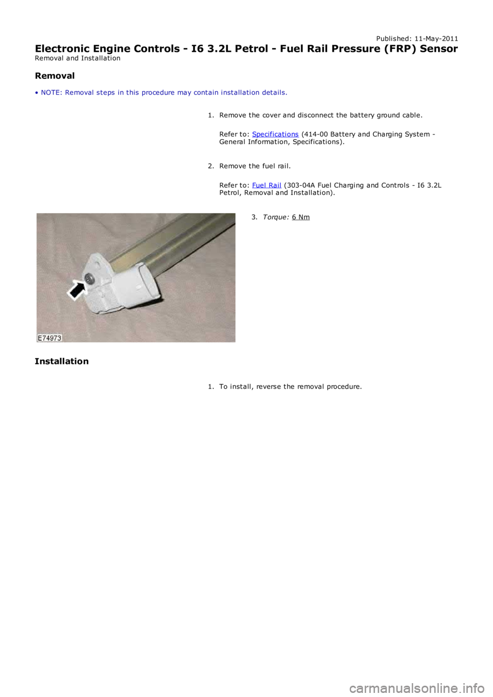
2. T orque:
6 Nm 3.
Installation To i nst all , revers e t he removal procedure.
1.
Page 1533 of 3229
DPF Air Management Module
The DPF air management modul e control s t he fol lowing funct ions :
EGR controlTurbocharger boos t pres sure cont rolInt ake air t emperature and pres s ure control.
Duri ng act ive regenerat ion, t he EGR operat ion i s dis abl ed and t he cl osed-loop acti vat ion of t he t urbocharger boostcont rol ler is calculat ed. The ai r management module cont rols the ai r in t he int ake manifol d t o a predet ermi ned level ofpres s ure and t emperat ure. Thi s cont rol i s required t o achi eve the correct i n-cylinder condi ti ons for s table and robustcombus t ion of t he post i njected fuel.
The module controls t he i nt ake air t emperature by actuati ng t he EGR t hrott le and by adjus tment of t he turbocharger boos tpres s ure control.
DPF Co-ordinator Module
The DPF co-ordi nat or module react s t o a regenerat ion reques t from the s upervis or module by i nit iat ing and co-ordi nat ingt he foll owing DPF regenerat ion reques t s :
EGR cut-offTurbocharger boos t pres sure cont rolEngi ne load i ncreaseControl of air press ure and temperat ure in t he i nt ake manifoldFuel i njecti on cont rol.
W hen t he s upervis or modul e i ss ues a regenerat ion reques t , the co-ordinator module reques t s EGR cut-off and aregenerat ion s peci fi c turbocharger boos t pres s ure control. It then wai ts for a feedback s ignal from t he EGR s ys t emconfirming that the EGR val ve is cl osed.
W hen t he EGR valve i s clos ed, t he co-ordi nator module i nit iat es reques t s t o increas e engine l oad by cont roll ing t he i nt akeair t emperature and pres s ure.
Once confirmati on is recei ved that int ake condit ions are cont rol led or a cali brati on t ime has expired, the co-ordinatormodule t hen changes t o a s t ate awai ti ng an accelerator pedal release manoeuver from t he dri ver. If t his occurs or acal ibrat ion ti me has expired, t he co-ordi nat or modul e generates a request t o control fuel injecti ons to increas e exhaus tgas temperature.
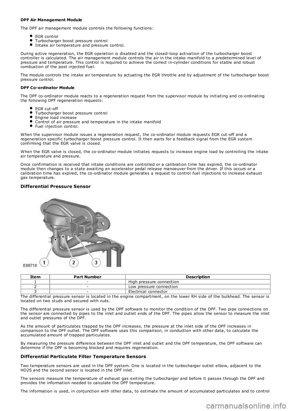
Differential Pressure Sensor
ItemPart NumberDescription
1-High press ure connect ion2-Low pres s ure connect ion
3-Electrical connect or
The different ial pres s ure s ensor i s located i n t he engi ne compart ment , on t he lower RH si de of the bul khead. The sens or islocated on two st uds and s ecured wit h nuts .
The different ial pres s ure s ensor i s us ed by the DPF software t o monit or the condit ion of t he DPF. Two pi pe connecti ons ont he sens or are connect ed by pipes t o t he inlet and out let ends of t he DPF. The pipes all ow t he s ens or to measure t he inletand outl et press ures of t he DPF.
As t he amount of parti culat es t rapped by the DPF increases , t he pres sure at t he inlet s i de of the DPF i ncreas es i ncomparis on t o t he DPF outl et . The DPF s oft ware us es t his compari son, in conduct ion wit h other data, t o calculate theaccumulat ed amount of trapped part iculat es.
By meas uri ng the press ure difference between t he DPF i nl et and out let and t he DPF t emperature, the DPF s oftware candetermine i f the DPF is becoming bl ocked and requires regenerat ion.
Differential Particulate Filter Temperature Sensors
Two t emperature s ensors are us ed i n t he DPF s ys t em. One is locat ed i n t he turbocharger out let el bow, adjacent to theHO2S and t he s econd s ensor i s located i n t he DPF inl et .
The s ens ors measure t he temperat ure of exhaust gas exit ing the t urbocharger and before i t pas s es t hrough the DPF andprovides t he informat ion needed to cal cul at e t he DPF t emperature.
The informat ion i s us ed, i n conjunct ion wi th other dat a, to est imat e t he amount of accumulat ed parti cul ates and t o control
Page 1559 of 3229
1
2
3
1
2
3
4
5
6
7
1
2
1
Is a bl ockage or res t ri ct ion evident?YesCLEAR/REPAIR t he blocked or rest ri cted fuel l ine and t es t the s ys tem for normal operat ion.NoCHECK for DTCs and s ymptoms indicati ng anot her caus e for t he problem.REFER t o: Electroni c Engi ne Controls (303-14A Electroni c Engine Controls - I6 3.2L Pet rol , Diagnos i sand Tes t ing).
PINPOINT TEST B : CHECK THE FU EL SYSTEM PRESSURE
T ESTCONDIT IONSDET AILS/RESULT S/ACT IONS
B1: CHECK T HE PUMP ACT IVIT YRemove the rear s eat cus hion.REFER t o: Rear Seat Cus hi on (501-10 Seat ing, Removal and Inst all ati on).
Set i gni ti on s tat us to ON, engi ne OFF.
Li s ten for pump nois e.
Can the fuel pump be heard runni ng?YesGO t o B2.NoCHECK for DTCs .REFER t o: Electroni c Engi ne Controls (303-14A Electroni c Engine Controls - I6 3.2L Pet rol , Diagnos i sand Tes t ing).
B2: CHECK T HE FUEL SYST EM PRESSURE
W ARNING: This procedure invol ves fuel handl ing. Be prepared for fuel s pi ll age at al l ti mes andal ways obs erve fuel handli ng precaut ions . Fai lure to fol low t hese ins truct ions may res ul t in pers onali njury.
Make sure t he vehi cl e is in Park and apply the parki ng brake.
Set i gni ti on s tat us to OFF
• NOTE: Pl ace sui table abs orbent mat erial around t he Schraeder valve t o abs orb any spil lage whenconnect ing t he gauge set .
Connect adapt er 310-162 and gauge as sembl y 310-116 t o t he fuel Schraeder valve. Remove theabs orbent mat erial and dis pos e of safely.Dis connect and pl ug t he vacuum hos e from the press ure regulat or.
Open the valve on the fuel press ure gauge and adapter 310-116/162.
Set i gni ti on s tat us to ON, engi ne OFF.
Record the fuel press ure reading.
Is t he fuel pres s ure 3.6 - 4.2 bar (52.2 - 60.9 l b/in²)?YesGO t o B3.NoCHECK for DTCs .REFER t o: Electroni c Engi ne Controls (303-14A Electroni c Engine Controls - I6 3.2L Pet rol , Diagnos i sand Tes t ing).B3: CHECK T HE FUEL SYST EM PRESSURE WIT H T HE ENGINE CRANKING
Appl y foot brake and pres s s tart but t on.
Record the fuel press ure reading when engine cranki ng.
Is t he fuel pres s ure 3.6 - 4.2 bar (52.2 - 60.9 l b/in²)?YesGO t o B4.NoCHECK for DTCs .REFER t o: Electroni c Engi ne Controls (303-14A Electroni c Engine Controls - I6 3.2L Pet rol , Diagnos i sand Tes t ing).B4: CHECK T HE FUEL SYST EM PRESSURE WIT H T HE ENGINE IDLING (WHERE PO SSIBLE)
W it h engine runni ng.
Is t he fuel pres s ure 3.6 - 4.2 bar (52.2 - 60.9 l b/in²)?YesCHECK for DTCs and s ymptoms indicati ng anot her caus e of the probl em.REFER t o: Electroni c Engi ne Controls (303-14A Electroni c Engine Controls - I6 3.2L Pet rol , Diagnos i sand Tes t ing).NoCHECK the fuel pump module power and ground circui ts .
Page 1770 of 3229
23-Transmis s ion warni ng indi cat or (low li ne only)
24-Hil l Des cent Cont rol (HDC) fault i ndi cat or (l ow li ne only)
25-Door open i ndi cat or (l ow li ne only)26-Engi ne management s yst em warning i ndicat or (l ow l ine only)
27-Side l amp indicat or
28-Dynami c Stabil it y Control (DSC) indicat or29-HDC acti ve indicator
30-Ant i-t heft alarm i ndi cat or
31-Glow pl ug indicat or (dies el vehicles onl y)32-Fuel fired boos ter heater i ndi cat or (i f fi tt ed)
The low li ne ins trument cl ust er cont ains 39 i ndi cat ors , the hi gh li ne ins t rument clus ter 27. The indicators in hi gh li neins t rument clus ters are s upplemented by mess ages in the mess age cent er.For addit ional informat ion, refer t o: Informat ion and Mes s age Cent er (413-08 Informat ion and Mes s age Cent er, Des cript ionand Operat ion).
The warni ng indicators can be s plit i nto 2 groups ; sel f cont roll ed and ext ernall y cont rol led. Self cont rol led warni ngindicat ors are dependent on software l ogi c wit hin t he i ns t rument clus ter for act ivati on. External ly controll ed indicators ares uppl ied wi th current from anot her s yst em cont roll ing module or ill uminat ed by the ins trument cl us t er on receipt of amedium s peed CAN bus mes sage from the CJB.
Ignition/No Charge Indicator
The ignit ion/no charge indicator i s cont rol led by t he ins t rument clus ter s oft ware and i ll uminated by medium speed CAN buss ignals from the ECM via t he CJB. The indicator il lumi nat es i n a red col or when the vehicle ent ers power mode 6 and isexti nguis hed when t he engine i s s tart ed.
If the i ndi cat or remai ns ill uminat ed aft er the engine has s t art ed or ill uminat es when drivi ng, t he alt ernator charge out puthas fai led.
Low Oil Pressure Warning Indicator
The low oil pres s ure warning i ndi cat or is i lluminated by t he i ns t rument clus ter on recei pt of a medium speed CAN buss ignal from t he CJB. The s ignal ori gi nates i n t he ECM and is generat ed by t he engi ne oil l evel s ens or on petrol vehicl es andt he engi ne oil pres s ure s ensor on di esel vehi cles .
The indicat or i ll uminates i n a red color when t he vehi cl e enters power mode 6 for a 3 s econd bulb check. If t he bul bs ubs equent ly ill uminat es when the engine is runni ng, t he engine s houl d be s t opped i mmediat ely i t is s afe to do s o.
Malfunction Indicator Lamp
The Malfunct ion Indicat or Lamp (MIL) i s il lumi nat ed by t he ins trument cl ust er on receipt of a medi um s peed CAN bus s ignalfrom the CJB. The si gnal originat es in t he ECM and i s generated if an On-Board Diagnos ti c (OBD) fault has been det ectedwhich wi ll caus e excess i ve emis s ions output. Thi s may rel ate to ei ther an engine management or trans mi ss i on fault .
The MIL is ill uminat ed in an amber color when t he vehi cl e enters power mode 6 for a 3 s econd bul b check. The bul b checkin thi s ins tance is carri ed out by the ECM vi a t he CJB, not t he ins trument cl ust er. If t he MIL subs equent ly i lluminates t hevehi cl e s houl d be i nterrogated us ing t he Land Rover approved diagnost ic sys tem at the earli es t opport uni ty.
Safety Belt Warning Indicator
The s afety bel t warni ng indicator wi ll il lumi nat e i n a red color on receipt of a medi um s peed CAN bus s ignal from t he CJB.The s ignal origi nat es in the Res traint s Cont rol Module (RCM), which monit ors the s t at us of t he occupant clas s ificati ons ys t em and s wi tches located i n t he s afety bel t buckles .
Three vari ati ons of warning are avai lable depending on vehicle confi gurati on:
Reminder (al l vehicl es except Nort h Ameri can Specificati on (NAS) vehicles )Federal Mot or Vehi cl e Safet y Standard (FMVSS) 208 remi nder (NAS vehi cles only)Belt Mi nder
The condi ti ons for s afety bel t warning indicator il lumi nat ion are as follows :
Reminder
Vehicle i n power mode 6Dri vers s afet y belt not s ecured in i ts buckleLarge pas senger det ect ed i n front pas s enger s eat wit h an uns ecured safety bel t.
The warni ng indicator wi ll remai n i lluminated unt il eit her t he i gni ti on is swi tched off or condi ti ons 2 and 3 no longer exis t .
FMVSS-208 Reminder
Vehicle i n power mode 6Dri vers s afet y belt not s ecured in i ts buckle.
The warni ng indicator wi ll remai n i lluminated for 65 s econds and wil l be accompanied by a si ngl e 6 second chi me from theins t rument clus ter s ounder.
• NOTE: The warni ng indicator and chime wil l not acti vat e i f thes e condi ti ons aris e 75 seconds aft er t he vehicle hasentered power mode 6.
The warni ng indicator wi ll be exti ngui shed and t he s ounder cancell ed if t he i gni ti on is s wi tched off or t he dri ver's s afet ybelt i s s ecured in i ts buckle.
Belt Mi nder
Page 1791 of 3229
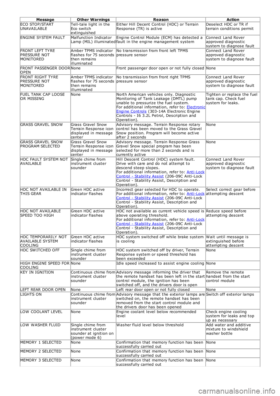
MessageO ther WarningsReasonAction
ECO STOP/STARTUNAVAILABLETel l-tal e li ght in t heEco swi tchext inguis hed
Eit her Hi ll Decent Control (HDC) or TerrainRespons e (TR) i s act iveDes elect HDC or TR i fterrain condit ions permi t
ENGINE SY STEM FAULTMalfunct ion Indi cat orLamp (MIL) il lumi nat edEngi ne Cont rol Module (ECM) has detected afault i n t he engi ne management s ys temConnect Land Roverapproved di agnos ti csys tem t o diagnos e faultFRONT LEFT TY REPRESSURE NOTMONITORED
Amber TPMS indicatorfl ashes for 75 secondsthen remainsil lumi nat ed
No t rans mis s ion from front left TPMSpres sure s ensorConnect Land Roverapproved di agnos ti csys tem t o diagnos e fault
FRONT PASSENGER DOOROPENNoneFront pas s enger door open or not fully cl osedNone
FRONT RIGHT TY REPRESSURE NOTMONITORED
Amber TPMS indicatorfl ashes for 75 secondsthen remainsil lumi nat ed
No t rans mis s ion from front ri ght TPMSpres sure s ensorConnect Land Roverapproved di agnos ti csys tem t o diagnos e fault
FUEL TANK CAP LOOSEOR MISSINGNoneNort h American vehi cl es onl y. Diagnos t icMonit oring of Tank Leakage (DMTL) pumpunabl e to pres surize t he fuel s yst em.For addit ional informati on, refer t o: Elect roni cEngi ne Cont rol s (303-14A Electroni c Engi neCont rol s - I6 3.2L Pet rol, Des cri pt ion andOperati on).
Ti ght en or repl ace t he fueltank cap. Check fuelsys tem for l eaks .
GRASS GRAVEL SNOWGras s Gravel SnowTerrai n Res pons e i condis played in mess agecent er
Advi sory mes s age. Terrain Res pons e rotarycont rol has been moved to the Grass GravelSnow posi ti on. Program will become acti veaft er 2 s econds
None
GRASS GRAVEL SNOWPROGRAM SELECTEDGras s Gravel SnowTerrai n Res pons e i condis played in mess agecent er
Advi sory mes s age. Terrain Res pons e Gras sGravel Snow special program has beens el ect ed for more t han 2 s econds and i scurrent ly acti ve
None
HDC FAULT SY STEM NOTAVAILABLESingle chime fromins trument cl ust ers ounder
Hil l Des cent Cont rol (HDC) sys tem faul t.Dri ve wit h care and do not at tempt t odes cend s teep s lopes .For addit ional informati on, refer t o: Ant i-LockCont rol - St abi li ty As s is t (206-09C Anti -LockCont rol - St abi li ty As s is t , Des cri pti on andOperati on).
Connect Land Roverapproved di agnos ti csys tem t o diagnos e fault
HDC NOT AVAILABLE INTHIS GEARGreen HDC act iveindicator flas hesIncorrect gear s el ect ed for HDC to operate.For addit ional informati on, refer t o: Ant i-LockCont rol - St abi li ty As s is t (206-09C Anti -LockCont rol - St abi li ty As s is t , Des cri pti on andOperati on).
Sel ect correct gear beforeat t empt ing des cent
HDC NOT AVAILABLESPEED TOO HIGHGreen HDC act iveindicator flas hesHDC not avai lable as current vehi cl e s peed isabove operat ing t hres hold.For addit ional informati on, refer t o: Ant i-LockCont rol - St abi li ty As s is t (206-09C Anti -LockCont rol - St abi li ty As s is t , Des cri pti on andOperati on).
Reduce s peed beforeat t empt ing des cent
HDC TEMPORARILY NOTAVAILABLE SY STEMCOOLING
Green HDC act iveindicator flas hesHDC s yst em swi tched off whi le brake s ys t emis cooli ngW ait unt il mes sage i sext inguis hed beforeat t empt ing des cent
HDC SW ITCHED O FFSingle chime fromins trument cl ust ers ounder
HDC s yst em swi tched off by driver, TerrainRespons e s ys t em or s peed thres hold hasbeen exceeded
None
HIGH ENGINE SPEED FORCOOLINGNoneIdl e s peed increased to as s is t engine cool ingNone
KEY IN IGNITIONCont inuous chi me fromins trument cl ust ers ounder
Advi sory mes s age informing the driver thatthe remot e hands et has been left i n t he s tartcont rol module, t he ignit ion has beens wit ched off, and t he dri vers door i s open
Remove t he remotehands et from t he s tartcontrol modul e
LEFT REAR DOOR O PENNoneLeft rear door open or not ful ly cl os edNone
LIGHTS ONCont inuous chi me fromins trument cl ust ers ounder
Advi sory mes s age that t he ext eri or l amps ares wit ched on, t he remot e hands et has beenremoved from the s t art control modul e andthe drivers door has been opened
Swi tch off ext eri or lamps
LOW COOLANT LEVELNoneEngi ne cool ant l evel below recommendedlevelCheck engine cool ingsys tem for l eaks and t opup as neces sary
LOW W ASHER FLUIDSingle chime fromins trument cl ust ers ounder at ignit ion on(power mode 6)
W as her flui d level bel ow t hres hol dAdd water and addi ti vemixt ure t o wi nds hiel dwas her bott le
MEMORY 1 SELECTEDNoneConfirmati on t hat memory funct ion has beens uccess ful ly carried outNone
MEMORY 2 SELECTEDNoneConfirmati on t hat memory funct ion has beens uccess ful ly carried outNone
MEMORY 3 SELECTEDNoneConfirmati on t hat memory funct ion has beens uccess ful ly carried outNone
Page 2703 of 3229
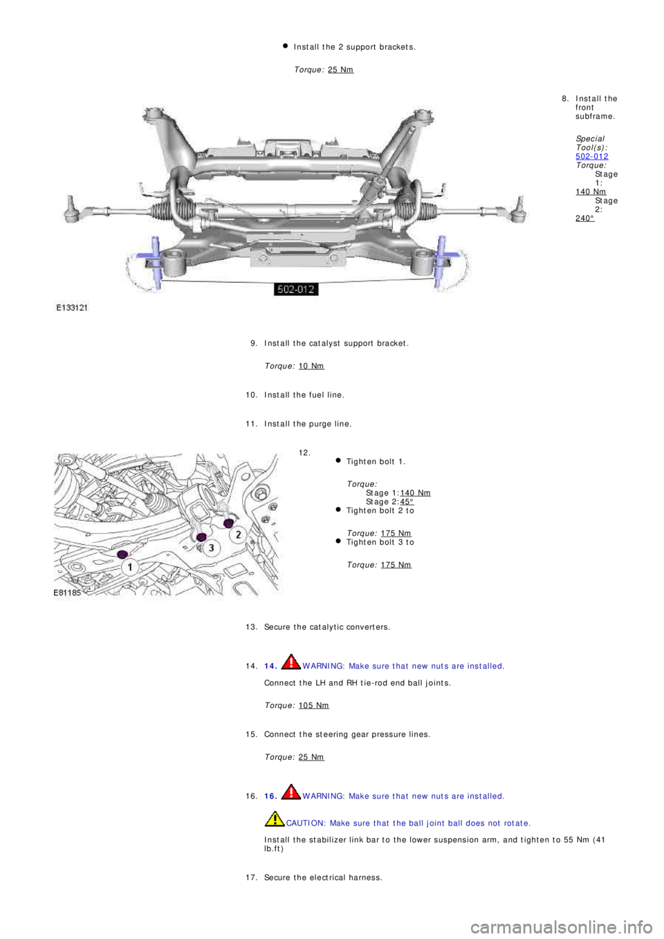
St a g e
1:
St a g e
2:
St a g e 1:
St a g e 2: Install the 2 support brackets.
Torque: 25 Nm
Install the
front
subframe.
Sp e c i a l
T ool (s ):
502-012
Torque:
140 Nm
240°
8.
Install the catalyst support bracket.
Torque: 10 Nm
9.
Install the fuel line. 10.
Install the purge line. 11.
Tighten bolt 1.
Torque:
140 Nm
45°Tighten bolt 2 to
Torque: 175 Nm
Tighten bolt 3 to
Torque: 175 Nm
12.
Secure the catalytic converters. 13.
14.
WARNING: Make sure that new nuts are installed.
Connect the LH and RH tie-rod end ball joints.
Torque: 105 Nm14.
Connect the steering gear pressure lines.
Torque: 25 Nm
15.
16.
WARNING: Make sure that new nuts are installed.
CAUTION: Make sure that the ball joint ball does not rotate.
Install the stabilizer link bar to the lower suspension arm, and tighten to 55 Nm (41
lb.ft) 16.
Secure the electrical harness. 17.
Page 2756 of 3229
Introduction
36
L
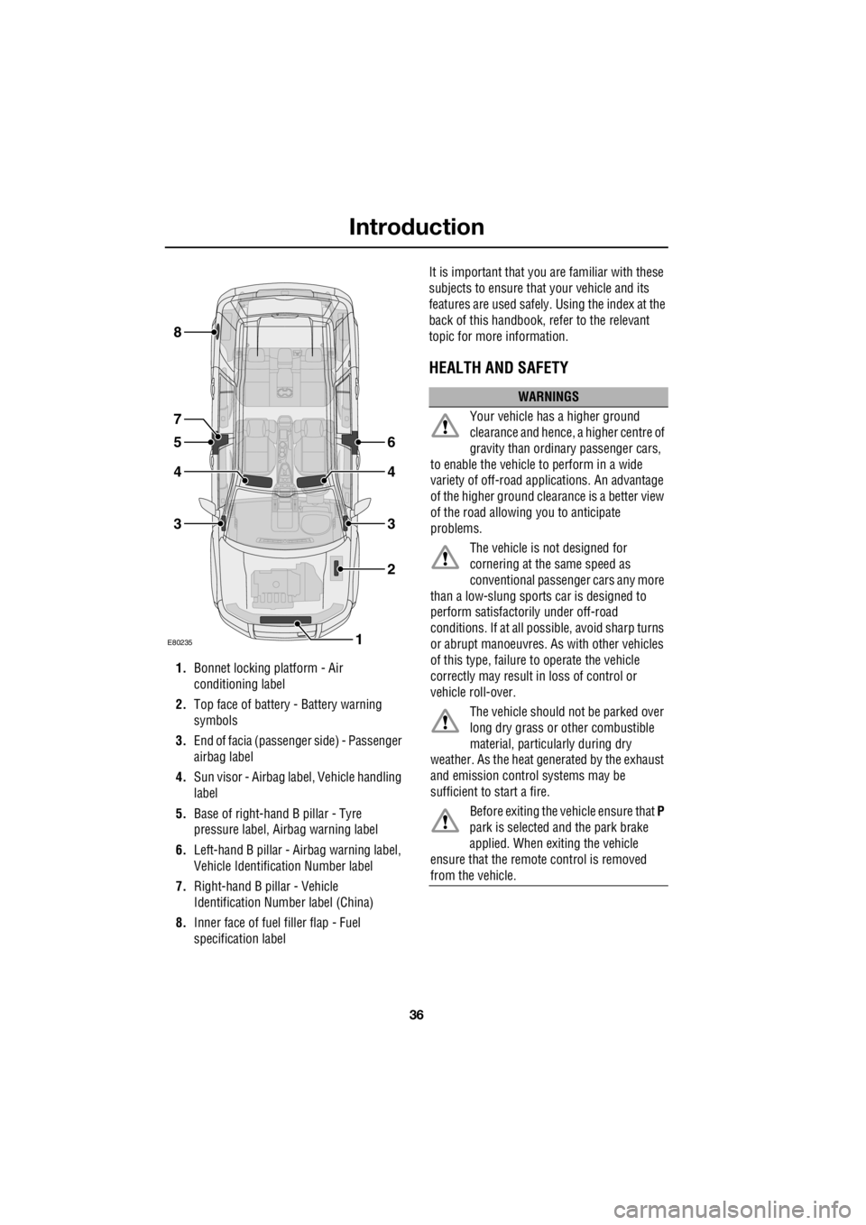
1. Bonnet locking platform - Air
conditioning label
2. Top face of battery - Battery warning
symbols
3. End of facia (passenger side) - Passenger
airbag label
4. Sun visor - Airbag label, Vehicle handling
label
5. Base of right-hand B pillar - Tyre
pressure label, Ai rbag warning label
6. Left-hand B pillar - Airbag warning label,
Vehicle Identification Number label
7. Right-hand B pillar - Vehicle
Identification Number label (China)
8. Inner face of fuel filler flap - Fuel
specification label It is important that you are familiar with these
subjects to ensure that your vehicle and its
features are used safely. Using the index at the
back of this handbook, re fer to the relevant
topic for more information.
HEALTH AND SAFETY
E80235
6
4
3
2
1
5
4
3
8
7
WARNINGS
Your vehicle has a higher ground
clearance and hence, a higher centre of
gravity than ordina ry passenger cars,
to enable the vehicle to perform in a wide
variety of off-road app lications. An advantage
of the higher ground clea rance is a better view
of the road allowing you to anticipate
problems.
The vehicle is not designed for
cornering at the same speed as
conventional passenge r cars any more
than a low-slung sports car is designed to
perform satisfactori ly under off-road
conditions. If at all possible, avoid sharp turns
or abrupt manoeuvres. As with other vehicles
of this type, failure to operate the vehicle
correctly may result in loss of control or
vehicle roll-over.
The vehicle should no t be parked over
long dry grass or other combustible
material, particul arly during dry
weather. As the heat ge nerated by the exhaust
and emission control systems may be
sufficient to start a fire.
Before exiting the vehicle ensure that P
park is selected and the park brake
applied. When exiting the vehicle
ensure that the remote control is removed
from the vehicle.
Page 2848 of 3229
Driving hints
128
L
Driving hintsGENERAL DRIVING POINTS
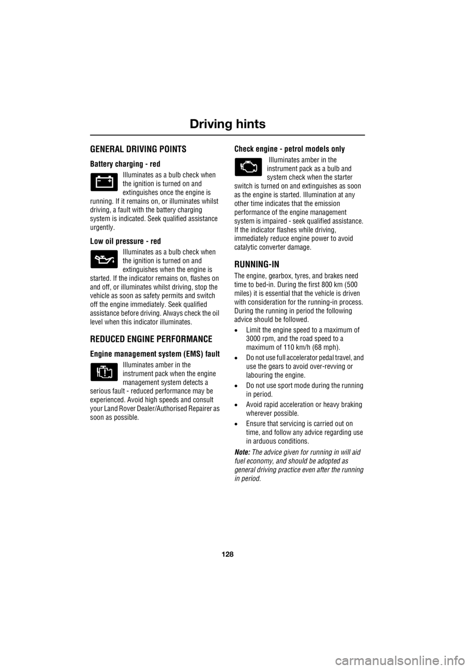
Battery charging - red
Illuminates as a bulb check when
the ignition is turned on and
extinguishes once the engine is
running. If it remains on, or illuminates whilst
driving, a fault with the battery charging
system is indicated. Seek qualified assistance
urgently.
Low oil pressure - red
Illuminates as a bulb check when
the ignition is turned on and
extinguishes when the engine is
started. If the indicator remains on, flashes on
and off, or illuminates whilst driving, stop the
vehicle as soon as safety permits and switch
off the engine immediat ely. Seek qualified
assistance before driving. Always check the oil
level when this indicator illuminates.
REDUCED ENGINE PERFORMANCE
Engine management syst em (EMS) fault
Illuminates amber in the
instrument pack when the engine
management system detects a
serious fault - reduce d performance may be
experienced. Avoid high speeds and consult
your Land Rover Dealer/A uthorised Repairer as
soon as possible.
Check engine - petrol models only
Illuminates amber in the
instrument pack as a bulb and
system check when the starter
switch is turned on and extinguishes as soon
as the engine is starte d. Illumination at any
other time indicates that the emission
performance of the engine management
system is impaired - seek qualified assistance.
If the indicator flashes while driving,
immediately reduce e ngine power to avoid
catalytic converter damage.
RUNNING-IN
The engine, gearbox, tyre s, and brakes need
time to bed-in. During the first 800 km (500
miles) it is essential th at the vehicle is driven
with consideration for the running-in process.
During the running in period the following
advice should be followed.
• Limit the engine speed to a maximum of
3000 rpm, and the road speed to a
maximum of 110 km/h (68 mph).
• Do not use full accelerator pedal travel, and
use the gears to avoid over-revving or
labouring the engine.
• Do not use sport mode during the running
in period.
• Avoid rapid accelerati on or heavy braking
wherever possible.
• Ensure that servicing is carried out on
time, and follow any advice regarding use
in arduous conditions.
Note: The advice given for running in will aid
fuel economy, and s hould be adopted as
general driving practice even after the running
in period.