2006 LAND ROVER FRELANDER 2 fuse box
[x] Cancel search: fuse boxPage 1202 of 3229
12-Res trai nts Cont rol Module (RCM)
13-Knock sens ors (2 off)
14-Fuel rail t emperature/pres s ure s ens or15-Clockspring
16-Terrain respons e cont rol module
17-Trans mis s ion Cont rol Module (TCM)18-ABS module
19-Diagnos ti c socket
20-CJB
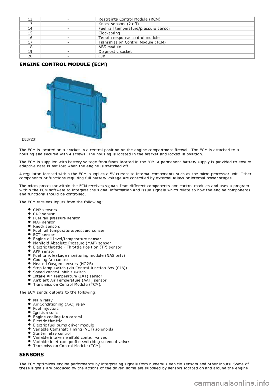
ENGINE CONTROL MODULE (ECM)
The ECM i s located on a bracket i n a central pos i ti on on the engi ne compartment firewal l. The ECM is at tached to ahous i ng and s ecured wit h 4 s crews . The hous i ng is l ocat ed in the bracket and locked in pos it ion.
The ECM i s s uppl ied wi th bat tery volt age from fuses l ocat ed in the BJB. A permanent batt ery s upply i s provided t o ens ureadapt ive dat a is not l ost when the engine i s s wit ched off.
A regul ator, locat ed wi thin the ECM, s upplies a 5V current t o i nt ernal components such as t he mi cro-proces s or unit . Ot hercomponents or funct ions requi ri ng ful l bat tery vol tage are cont rol led by ext ernal relays or int ernal power s t ages .
The mi cro-proces sor wi thi n the ECM receives s ignals from different component s and cont rol modules and us es a programwit hin the ECM software t o int erpret t he s ignal informat ion and i ss ue s ignals whi ch rel at e t o how the engine component sand functi ons should be cont rol led.
The ECM recei ves i nput s from the foll owing:
CMP s ensorsCKP s ensorFuel rail pres s ure s ensorMAF s ensorKnock s ens orsFuel rail t emperature/pres s ure s ensorECT s ens orEngi ne oil l evel/t emperature s ens orManifol d Abs olute Pres sure (MAP) sens orElectric t hrot tl e - Throt tl e Posi ti on (TP) s ens orAPP s ens orFuel t ank leakage monit oring modul e (NAS onl y)Cooling fan controlHeated Oxygen s ens ors (HO2S)Stop lamp s wi tch (via Central Juncti on Box (CJB))Speed cont rol inhibi t swi tchInt ake Air Temperat ure (IAT) s ens orAmbient Air Temperat ure (AAT) s ens orTrans mis s ion Cont rol Modul e (TCM).
The ECM s ends out puts to t he followi ng:
Main relayAir Condit ioning (A/C) relayFuel i njectorsIgni ti on coi lsEngi ne cool ing fan cont rolElectric t hrot tl eElectric fuel pump driver moduleVari abl e Cams haft Timing (VCT) s olenoidsStarter rel ay cont rolVari abl e int ake manifol d control valvesVari abl e inl et cam profile swit ching sol enoi d val vesTrans mis s ion Cont rol Modul e (TCM).
SENSORS
The ECM opt imi zes engine performance by interpreti ng s ignals from numerous vehicle sens ors and ot her i nput s. Some oft hes e s ignals are produced by t he act ions of t he dri ver, some are s uppli ed by s ens ors locat ed on and around t he engine
Page 1556 of 3229
Publi shed: 13-Jul-2011
Fuel Tank and Lines - I6 3.2L Petrol - Fuel Tank and Lines
Diagnosi s and Tes ti ng
Principles of Operation
For a detail ed descripti on of the fuel tank and l ines s ys t ems , refer t o t he rel evant Des cript ion and Operat ion s ecti on in theworks hop manual .REFER to: Fuel Tank and Lines (310-01A Fuel Tank and Lines - I6 3.2L Pet rol , Descri pti on and Operat ion).
Inspection and Verification
CAUTION: Di agnos is by s ubs ti tut ion from a donor vehicle is NO T acceptabl e. Subs ti tut ion of cont rol modules doesnot guarant ee confirmat ion of a faul t, and may als o caus e addit ional fault s i n t he vehi cl e being t est ed and/or t he donorvehi cl e.
• NOTE: For di agnos t ic purpos es the cyli nders are divided i nt o t wo banks: Bank 1 - Cyl inder numbers 1, 2 and 3. Bank 2 -Cylinders 4, 5 and 6
1. Verify t he cus t omer concern.1.
2. Vis ually ins pect for obvious s igns of mechani cal or electrical damage.2.
Visual Inspection
MechanicalElectricalFuel l eaksDamaged fuel l inesDamaged push connect fit t ingsFuel l evelFuel contami nati on/grade/quali tyDamaged fuel t ank fi ller pipe capDamaged fuel t ank fi ller pipe
FusesLoos e or corroded elect rical connect orsHarnes s esFuel Pump Dri ver Module (FPDM)Central Junct ion Box (CJB)Fuel pump relayEngine Control Modul e (ECM)
3. If an obvious cause for an obs erved or report ed concern is found, correct t he caus e (if pos s ible) beforeproceeding t o t he next s t ep.3.
4. If t he caus e is not vis ually evi dent , verify t he sympt om and refer t o t he Sympt om Chart, al ternat ively, check forDi agnos ti c Trouble Codes (DTCs) and refer t o t he DTC Index.4.
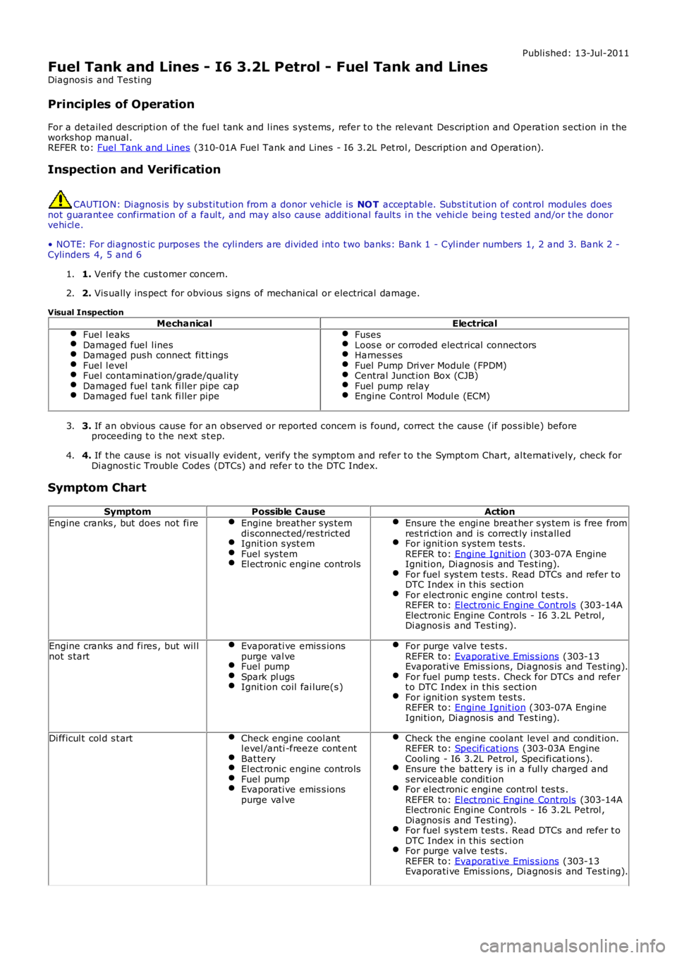
Symptom Chart
SymptomPossible CauseAction
Engine cranks , but does not fi reEngine breat her sys temdi sconnect ed/res trict edIgnit ion s yst emFuel sys temEl ect ronic engine controls
Ens ure t he engi ne breat her s ys tem is free fromres t ri ct ion and is correct ly i nst all edFor ignit ion s ys tem tes t s.REFER to: Engine Ignit ion (303-07A EngineIgni ti on, Di agnos is and Tes t ing).For fuel s ys t em t est s . Read DTCs and refer t oDTC Index in t his secti onFor elect roni c engi ne cont rol t es t s .REFER to: El ect ronic Engine Cont rols (303-14AElectronic Engine Controls - I6 3.2L Petrol ,Di agnos is and Tes ti ng).
Engine cranks and fires , but wil lnot s tartEvaporati ve emis s ionspurge val veFuel pumpSpark pl ugsIgnit ion coil fai lure(s )
For purge valve t est s .REFER to: Evaporati ve Emis s ions (303-13Evaporati ve Emis s ions, Di agnos is and Tes t ing).For fuel pump t es t s . Check for DTCs and refert o DTC Index in t his s ecti onFor ignit ion s ys tem tes t s.REFER to: Engine Ignit ion (303-07A EngineIgni ti on, Di agnos is and Tes t ing).
Di fficul t col d s t artCheck engi ne cool antl evel /anti -freeze cont entBat teryEl ect ronic engine controlsFuel pumpEvaporati ve emis s ionspurge val ve
Check the engine coolant level and condit ion.REFER to: Specifi cat ions (303-03A EngineCooli ng - I6 3.2L Petrol, Speci fi cat ions ).Ens ure t he batt ery i s in a ful ly charged ands erviceable condi ti onFor elect roni c engi ne cont rol t es t s .REFER to: El ect ronic Engine Cont rols (303-14AElectronic Engine Controls - I6 3.2L Petrol ,Di agnos is and Tes ti ng).For fuel s ys t em t est s . Read DTCs and refer t oDTC Index in t his secti onFor purge valve t est s .REFER to: Evaporati ve Emis s ions (303-13Evaporati ve Emis s ions, Di agnos is and Tes t ing).
Page 1591 of 3229
Publi s hed: 11-May-2011
Fuel Tank and Lines - TD4 2.2L Diesel - Fuel Tank and Lines
Diagnosi s and Tes ti ng
Principles of Operation
For a detail ed descripti on of the fuel tank and l ines s ys t ems , refer t o t he rel evant Des cript ion and Operat ion s ecti on in the
works hop manual .
REFER to: Fuel Tank and Lines (310-01B Fuel Tank and Lines - TD4 2.2L Dies el, Des cript ion and Operat ion).
Inspection and Verification CAUTION: Di agnos is by s ubs ti tut ion from a donor vehicle is
NO T acceptabl e. Subs ti tut ion of cont rol modules does
not guarant ee confirmat ion of a faul t, and may als o caus e addit ional fault s i n t he v ehi cl e being t est ed and/or t he donor
vehi cl e.
1. Verify t he cus t omer concern.
1.
2. Vis ually ins pect for obvious s igns of mechani cal or electrical damage.
2.
Visual Inspection Mechanical Electrical
Fuel l eaks Damaged fuel l ines
Damaged push connect fit t ings
Fuel l evel
Fuel contami nati on/grade/quali ty
Damaged fuel t ank fi ller pipe cap
Damaged fuel t ank fi ller pipe Fuses
Loos e or corroded elect rical connect ors
Harnes s es
Fuel Pump Dri ver Module (FPDM)
Central Junct ion Box (CJB)
Fuel pump relay
Engine Control Modul e (ECM)
3.
If an obvious cause for an obs erved or report ed concern is found, correct t he caus e (if pos s ible) before
proceeding t o t he next s t ep.
3.
4. If t he caus e is not vis ually evi dent , verify t he sympt om and refer t o t he Sympt om Ch art, al ternat ively, check for
Di agnos ti c Trouble Codes (DTCs) and refer t o t he DTC Index.
4.
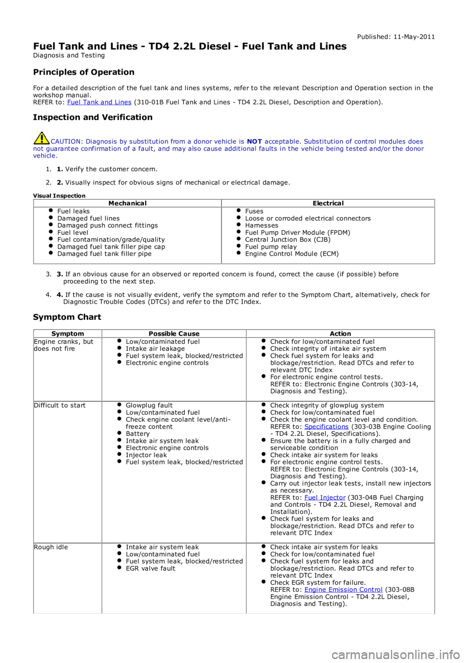
Symptom Chart Symptom Possible Cause Action
Engine cranks , but
does not fi re Low/contaminated fuel Intake air l eakage
Fuel sys tem leak, blocked/res tricted
El ect ronic engine controls Check for l ow/contami nat ed fuel
Check int egrit y of i nt ake air s yst em
Check fuel s yst em for leaks and
bl ockage/res t ri ct ion. Read DTCs and refer to
relevant DTC Index For electronic engine control t es ts .
REFER t o: Electroni c Engi ne Control s (303-14,
Diagnos is and Tes t ing). Di fficul t t o s tart
Gl owpl ug faul t Low/contaminated fuel
Check engi ne cool ant l evel /anti -
freeze cont ent Bat tery
Intake air s ys tem leak
El ect ronic engine controls
Injector l eak
Fuel sys tem leak, blocked/res tricted Check int egrit y of glowpl ug sys t em
Check for l ow/contami nat ed fuel
Check t he engi ne cool ant l evel and condi ti on.
REFER t o: Specificati ons (303-03B Engine Cool ing
- TD4 2.2L Di es el, Specificat ions ). Ens ure the bat tery is i n a full y charged and
servi ceable condit ion Check int ake air s yst em for leaks
For electronic engine control t es ts .
REFER t o: Electroni c Engi ne Control s (303-14,
Diagnos is and Tes t ing). Carry out i njector leak t est s , ins tal l new inject ors
as neces sary.
REFER t o: Fuel Injector (303-04B Fuel Charging
and Cont rols - TD4 2.2L Di esel , Removal and
Ins tal lati on). Check fuel s yst em for leaks and
bl ockage/res t ri ct ion. Read DTCs and refer to
relevant DTC Index Rough idl e
Intake air s ys tem leak Low/contaminated fuel
Fuel sys tem leak, blocked/res tricted
EGR val ve fault Check int ake air s yst em for leaks
Check for l ow/contami nat ed fuel
Check fuel s yst em for leaks and
bl ockage/res t ri ct ion. Read DTCs and refer to
relevant DTC Index Check EGR s ys tem for fai lure.
REFER t o: Engi ne Emis s ion Cont rol (303-08B
Engine Emis s ion Control - TD4 2.2L Di esel ,
Diagnos is and Tes t ing).
Page 1820 of 3229
If the el ect rolyt e level is l ow, top-up usi ng dis t ill ed water.
Maint enance free and Valve Regulat ed (AGM) bat teries are s eal ed and therefore cannot be topped up.
CHARGING SYSTEM TEST AND DIAGNOSIS
For al l vehi cl es , refer to the Chargi ng Syst em - Diagnos i s and Tes t ing i n s ect ion 414-00 of the W orks hop Manual.
VEHICLE QUIESCENT CURRENT TESTING
• NOTE: On vehicles fit t ed wit h a Bat tery Monit oring Sys t em (BMS), t he diagnos t ic routi ne for quies cent drai n t es t ing i nt he approved di agnos ti c s ys t em s hould be ut il ized.
• NOTE: If a cus t omer compl ains of a vehicle bat tery that dis charges cont inuousl y or when left for a prolonged period oft ime, it is recommended t hat a quies cent drai n tes t i s performed as des cribed below.
• NOTE: The batt ery drain s hould be meas ured usi ng an approved diagnos t ic s ys tem or a Digi tal Mult i-Meter (DVOM).
The vehi cl e s houl d be i n t he locked/armed st ate (for example vehi cl e alarm full y armed), al l doors , engine and luggagecompartment l ids are open and lat ched (s o as t o appear clos ed from an electrical point of view). The t es t s houl d t akeplace aft er the vehicle has ent ered s hutdown mode. The t ime taken for this to occur after t he igni ti on is s wi tched offvaries according t o model - Refer t o Quies cent Drain in s ecti on 414-00 of the W orks hop Manual .
• NOTE: W hen t he vehicle i s armed, t he effect of t he s ecurit y s ys t em Li ght Emi tt ing Diode (LED) flas hing i s to caus e apuls ati on in the meas ured current drain. In t hi s case, eit her the average current should be taken (usi ng a Di gi tal Mul ti -Meter (DVOM) wi th an averagi ng s ys t em) or the current reading t aken, ignori ng t he bri ef hi gh current peaks .
EQUIPMENT
Approved diagnos t ic s ys tem wit h current probe or Digit al Mul ti -Met er (DVOM) wit h current probe.
METHOD OF MEASUREMENT
Using an Approved Diagnostic System
1. Swit ch off all elect rical loads and ensure t hat t he i gni ti on is off.
2. Connect the current probe t o t he approved di agnos ti c s yst em.
3. Calibrate t he probe.
4. Ins t al l a clamp around the bat tery lead/junct ion box l ead.
5. Go t o t he Quies cent Current Tes t ing s ect ion.
Using a Digital Multi-Meter (DVOM)
• NOTE: Do not us e an i n-li ne DVOM to meas ure the qui escent drain on vehi cl es fi tt ed wi th an el ect roni c throt t le. Thecurrent exceeds t he maximum amount the fus e in the DVOM is capable of handling.
1. Swit ch off all elect rical loads and ensure t hat t he i gni ti on is off.
2. Connect the current probe t o t he DVOM.
3. Calibrate t he probe.
4. Ins t al l a clamp around the bat tery lead/junct ion box l ead.
5. Go t o t he fol lowing Qui escent Current Tes ti ng s ect ion.
QUIESCENT CU RRENT TESTING
1. Swit ch ignit ion t o ‘on’ or s elect ignit ion mode i n keyles s vehi cl es and s wit ch to ‘off’ (do not crank).
2. Remove key from i gni ti on s wit ch (where appl icabl e).
3. Open and lat ch all doors , hood and l uggage compart ment li d.
4. Lock t he vehi cle us ing t he remote funct ion on the remote hands et. (Single lock onl y t o avoi d volumet ri c alarm arming).
5. Remove any ot her pot enti al el ect ri cal drai ns such as acces s ori es plugged into acces sory s ockets .
6. Record the amperage readings after t he shut down period. The model specific Amperage readings for quies cent drain arereferenced in Qui escent Drain in secti on 414-00 of t he W orks hop Manual
7. Record the fi nal readi ng on the bat tery report form Appendi x B.
• NOTE: The preferred method of t est ing foll owing an exces s ive current cons umpti on fi gure i s t o use a current probearound i ndi vi dual junct ion box l eads t o t he various s us pect ed ci rcuit s t o ident ify a potent ial caus e. Thi s is in preference t ot he old met hod of removing fus es for t he fol lowing reasons :
Many modules t ake a cons i derabl e t ime to power down. Each t ime a fuse is removed and re-fi tt ed, t he quies centdrai n current may t ake an extended peri od of ti me t o ret urn to normal (t ypi cal ly up to 45 minut es ).The drai n may be caused by a module remaini ng act ive and prevent ing t he quies cent drai n from reduci ng to normallevels .The drai n may be caused by a rel ay winding that is act ivated. Pulli ng t he fus e can all ow t his t o ‘res et ’ and the drainwil l be los t and go un-di agnos ed.
Page 1830 of 3229
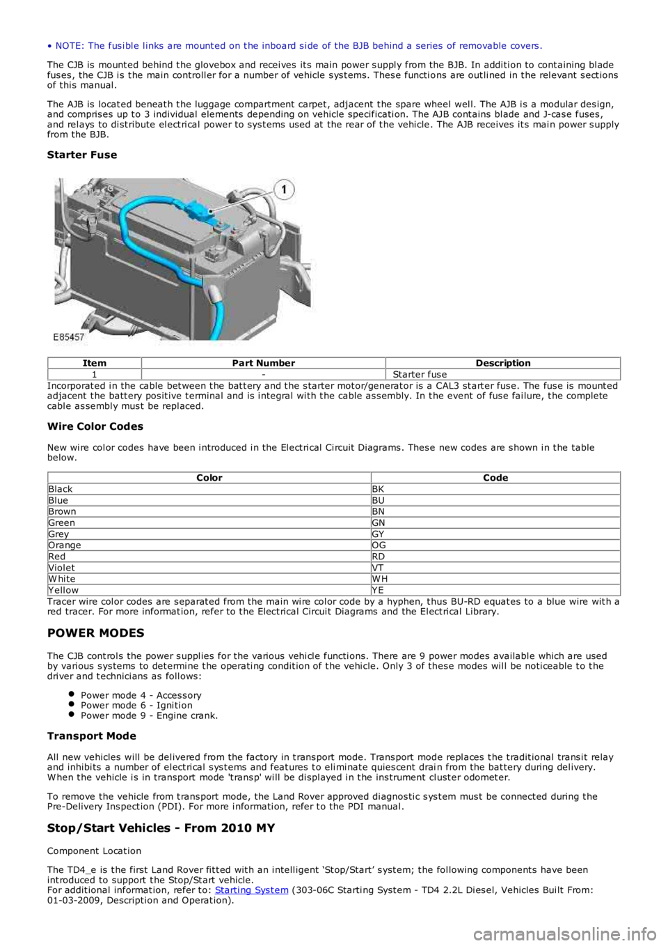
• NOTE: The fus i bl e l inks are mount ed on t he inboard s i de of the BJB behind a series of removable covers .
The CJB is mount ed behind t he glovebox and recei ves it s main power s uppl y from the BJB. In addi ti on to cont aining bl adefus es , the CJB i s t he main controll er for a number of vehicle s ys t ems. Thes e functi ons are out li ned in t he rel evant s ect ionsof thi s manual .
The AJB is locat ed beneat h t he luggage compartment carpet , adjacent t he spare wheel wel l. The AJB i s a modular des ign,and compris es up t o 3 individual elements depending on vehicle specificati on. The AJB cont ains bl ade and J-cas e fuses ,and rel ays to di st ribute el ect ri cal power to sys t ems used at the rear of t he vehi cle. The AJB receives it s mai n power s upplyfrom the BJB.
Starter Fuse
ItemPart NumberDescription
1-Starter fus e
Incorporat ed i n the cable bet ween t he bat t ery and t he s tarter mot or/generat or is a CAL3 st art er fus e. The fus e is mount edadjacent t he batt ery pos it ive t erminal and is i ntegral wi th t he cable as s embly. In the event of fus e fai lure, t he completecabl e as sembl y mus t be repl aced.
Wire Color Codes
New wi re col or codes have been i ntroduced i n the El ect ri cal Ci rcuit Di agrams . Thes e new codes are s hown i n t he tablebelow.
ColorCode
BlackBK
BlueBUBrownBN
GreenGN
GreyGYOrangeOG
RedRD
Viol etVTW hi teW H
Y ell owY E
Tracer wire col or codes are s eparat ed from the main wi re col or code by a hyphen, t hus BU-RD equat es to a blue wire wit h ared tracer. For more informat ion, refer to t he Elect rical Circui t Diagrams and the El ect ri cal Library.
POWER MODES
The CJB cont rol s the power s uppl ies for the vari ous vehi cl e functi ons. There are 9 power modes availabl e which are usedby vari ous s ys tems to det ermi ne t he operati ng condit ion of t he vehi cle. Only 3 of thes e modes wil l be noti ceable t o t hedri ver and t echnici ans as foll ows:
Power mode 4 - Acces s oryPower mode 6 - Igni ti onPower mode 9 - Engine crank.
Transport Mode
All new vehicles will be del ivered from the factory in t rans port mode. Trans port mode repl aces t he t radit ional trans i t relayand inhibi ts a number of el ect ri cal s ys t ems and feat ures t o eli mi nat e quies cent drain from the bat tery during del ivery.W hen t he vehicle i s in transport mode 't rans p' wi ll be di spl ayed i n t he ins trument cl ust er odomet er.
To remove the vehicle from t rans port mode, the Land Rover approved di agnos ti c s ys t em mus t be connect ed during t hePre-Delivery Ins pect ion (PDI). For more i nformati on, refer t o the PDI manual .
Stop/Start Vehicles - From 2010 MY
Component Locat ion
The TD4_e is t he first Land Rover fit t ed wit h an i ntell igent ‘St op/Start’ s yst em; t he fol lowing component s have beenint roduced to support t he Stop/St art vehicle.For addit ional informat ion, refer t o: Starti ng Sys t em (303-06C Starti ng Syst em - TD4 2.2L Di es el, Vehicles Bui lt From:01-03-2009, Descripti on and Operat ion).
Page 1835 of 3229
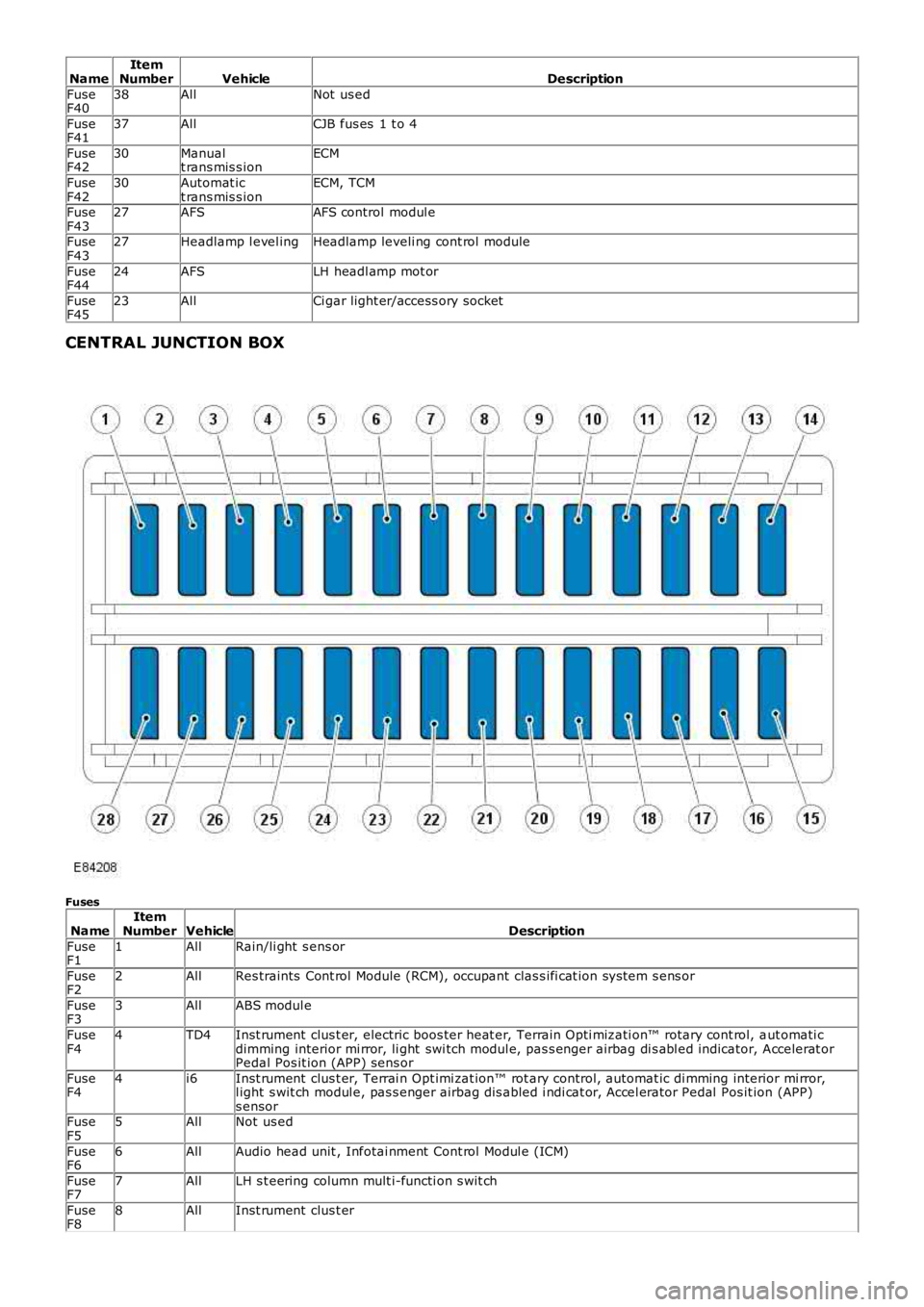
NameItemNumberVehicleDescription
FuseF4038AllNot us ed
FuseF4137AllCJB fus es 1 t o 4
FuseF4230Manualt rans mis s ionECM
FuseF4230Automat ict rans mis s ionECM, TCM
FuseF4327AFSAFS control modul e
FuseF4327Headlamp l evel ingHeadlamp leveli ng cont rol module
FuseF4424AFSLH headl amp mot or
FuseF4523AllCi gar light er/access ory socket
CENTRAL JUNCTION BOX
Fuses
NameItemNumberVehicleDescription
FuseF11AllRain/li ght s ens or
FuseF22AllRes traints Cont rol Module (RCM), occupant clas s ifi cat ion sys tem s ens or
FuseF33AllABS modul e
FuseF44TD4Inst rument clus t er, electric boos ter heat er, Terrain Opti mizati on™ rotary cont rol, aut omati cdimming interior mi rror, li ght swi tch modul e, pas s enger airbag di s abl ed indicator, Accelerat orPedal Pos it ion (APP) sens or
FuseF44i6Inst rument clus t er, Terrai n Opt imi zat ion™ rot ary control, automat ic di mming interior mi rror,l ight s wit ch modul e, pas s enger airbag dis abled i ndi cat or, Accel erator Pedal Pos it ion (APP)s ensorFuseF55AllNot us ed
FuseF66AllAudio head unit , Infotai nment Cont rol Modul e (ICM)
FuseF77AllLH s t eering column mult i-functi on s wit ch
FuseF88AllInst rument clus t er
Page 1836 of 3229
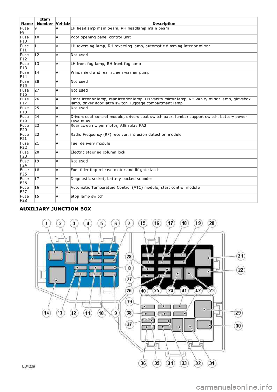
NameItemNumberVehicleDescription
FuseF99AllLH headlamp main beam, RH headlamp main beam
FuseF1010AllRoof openi ng panel cont rol unit
FuseF1111AllLH revers ing l amp, RH revers i ng lamp, automat ic di mmi ng int erior mi rror
FuseF1212AllNot us ed
FuseF1313AllLH front fog lamp, RH front fog lamp
FuseF1414AllW indshi eld and rear s creen was her pump
FuseF1528AllNot us ed
FuseF1627AllNot us ed
FuseF1726AllFront i nt eri or lamp, rear i nt eri or lamp, LH vanit y mirror l amp, RH vani ty mirror l amp, gl oveboxl amp, driver door l atch s wit ch, luggage compart ment lamp
FuseF1825AllNot us ed
FuseF1924AllDrivers s eat cont rol module, dri vers s eat swit ch pack, lumbar s upport s wi tch, bat t ery powers ave rel ayFuseF2023AllRear s creen wiper mot or, AJB rel ay RA2
FuseF2122AllRadio Frequency (RF) receiver, intrusi on detecti on module
FuseF2221AllFuel del ivery modul e
FuseF2320AllElect ric st eeri ng col umn lock
FuseF2419AllNot us ed
FuseF2518AllFuel fil ler flap release motor and l iftgate lat ch
FuseF2617AllDi agnos ti c s ocket, bat tery backed s ounder
FuseF2716AllAut omat ic Temperature Cont rol (ATC) modul e, st art control modul e
FuseF2815AllSt op lamp swi tch
AUXILIARY JUNCTION BOX
Page 1837 of 3229
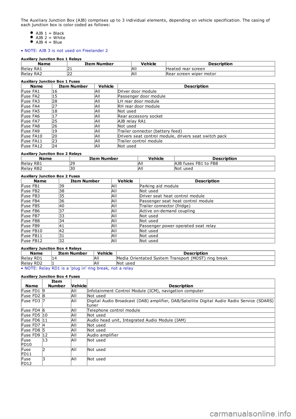
The Auxi li ary Junct ion Box (AJB) compris es up t o 3 i ndi vi dual el ement s , depending on vehicle specificati on. The casi ng ofeach junct ion box is color coded as foll ows:
AJB 1 = BlackAJB 2 = W hit eAJB 4 = Blue
• NOTE: AJB 3 i s not used on Freelander 2
Auxiliary Junction Box 1 Relays
NameItem NumberVehicleDescriptionRelay RA121AllHeat ed rear s creen
Relay RA222AllRear s creen wiper mot or
Auxiliary Junction Box 1 Fuses
NameItem NumberVehicleDescription
Fuse FA116AllDri ver door moduleFuse FA215AllPass enger door module
Fuse FA328AllLH rear door module
Fuse FA427AllRH rear door moduleFuse FA518AllNot used
Fuse FA617AllRear acces s ory socket
Fuse FA725AllAJB rel ay RA1Fuse FA826AllNot used
Fuse FA919AllTrail er connect or (bat tery feed)
Fuse FA1020AllDri vers s eat cont rol module, dri vers s eat s wi tch packFuse FA1123AllTrail er cont rol module
Fuse FA1224AllNot used
Auxiliary Junction Box 2 Relays
NameItem NumberVehicleDescriptionRelay RB129AllAJB fuses FB1 t o FB8
Relay RB230AllNot us ed
Auxiliary Junction Box 2 Fuses
NameItem NumberVehicleDescription
Fuse FB139Al lParki ng aid moduleFuse FB238Al lNot us ed
Fuse FB335Al lDriver seat heat cont rol module
Fuse FB436Al lPas senger seat heat cont rol moduleFuse FB540Al lTrai ler connector (fridge)
Fuse FB637Al lActi ve on-demand coupl ing
Fuse FB733Al lNot us edFuse FB834Al lNot us ed
Fuse FB941Al lPas senger power operat ed s eat relay
Fuse FB1042Al lNot us edFuse FB1131Al lNot us ed
Fuse FB1232Al lNot us ed
Auxiliary Junction Box 4 Relays
NameItem NumberVehicleDescriptionRelay RD114AllMedi a Orientat ed Syst em Transport (MOST) ring break
Relay RD21AllNot us ed
• NOTE: Relay RD1 is a 'plug i n' ring break, not a relay
Auxiliary Junction Box 4 Fuses
NameItemNumberVehicleDescriptionFuse FD19Al lInfotainment Control Modul e (ICM), navi gat ion computer
Fuse FD28Al lNot used
Fuse FD37Al lDigit al Audi o Broadcast (DAB) ampli fi er, DAB/Sat el li te Digit al Audi o Radi o Servi ce (SDARS)tuner
Fuse FD46Al lTel ephone control modul eFuse FD510Al lNot used
Fuse FD611Al lAudi o head unit , Int egrated Audio Modul e (IAM)
Fuse FD74Al lNot usedFuse FD85Al lNot used
Fuse FD912Al lAudi o ampli fi er
FuseFD1013Al lNot used
FuseFD112Al lNot used
FuseFD123Al lNot used