2006 LAND ROVER FRELANDER 2 torque
[x] Cancel search: torquePage 146 of 3229
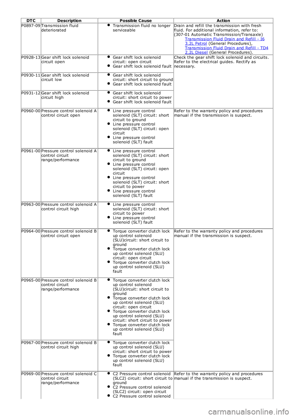
DT C
Description Possible Cause Action
P0897-09 Trans mis s ion flui d
deteri orat ed Transmis si on fluid no longer
servi ceable Drain and refill t he t rans mis s ion wi th fresh
fl ui d. For addit ional informati on, refer t o:
(307-01 Aut omati c Trans mis s ion/Trans axle)
Trans mi s si on Fluid Drain and Refil l - I6 3.2L Pet rol (General Procedures ),
Trans mi s si on Fluid Drain and Refil l - TD4 2.2L Dies el (General Procedures).
P0928-13 Gear shi ft l ock s olenoid
circuit open Gear s hift lock s olenoi d
ci rcuit : open ci rcuit Gear s hift lock s olenoi d faul t Check t he gear s hift lock s olenoid and circui ts .
Refer to the el ect ri cal guides . Rect ify as
neces sary.
P0930-11 Gear shi ft l ock s olenoid
circuit l ow Gear s hift lock s olenoi d
ci rcuit : short ci rcuit t o ground Gear s hift lock s olenoi d faul t
P0931-12
Gear shi ft l ock s olenoid
circuit hi gh Gear s hift lock s olenoi d
ci rcuit : short ci rcuit t o power Gear s hift lock s olenoi d faul t
P0960-00
Pres s ure control s olenoid A
cont rol circui t open Li ne pres s ure control
sol enoid (SLT) circuit : s hort
ci rcuit t o ground Li ne pres s ure control
sol enoid (SLT) circuit : open
ci rcuit Li ne pres s ure control
sol enoid (SLT) fault Refer to the warrant y pol icy and procedures
manual i f the t rans mis s ion is s us pect.
P0961-00 Pres s ure control s olenoid A
cont rol circui t
range/performance Li ne pres s ure control
sol enoid (SLT) circuit : s hort
ci rcuit t o ground Li ne pres s ure control
sol enoid (SLT) circuit : open
ci rcuit Li ne pres s ure control
sol enoid (SLT) circuit : s hort
ci rcuit t o power Li ne pres s ure control
sol enoid (SLT) fault P0963-00
Pres s ure control s olenoid A
cont rol circui t hi gh Li ne pres s ure control
sol enoid (SLT) circuit : s hort
ci rcuit t o power Li ne pres s ure control
sol enoid (SLT) fault P0964-00
Pres s ure control s olenoid B
cont rol circui t open Torque convert er cl ut ch lock
up cont rol s ol enoi d
(SLU)circui t: s hort ci rcuit t o
ground Torque convert er cl ut ch lock
up cont rol s ol enoi d (SLU)
ci rcuit : open ci rcuit Torque convert er cl ut ch lock
up cont rol s ol enoi d (SLU)
fault Refer to the warrant y pol icy and procedures
manual i f the t rans mis s ion is s us pect.
P0965-00 Pres s ure control s olenoid B
cont rol circui t
range/performance Torque convert er cl ut ch lock
up cont rol s ol enoi d
(SLU)circui t: s hort ci rcuit t o
ground Torque convert er cl ut ch lock
up cont rol s ol enoi d (SLU)
ci rcuit : open ci rcuit Torque convert er cl ut ch lock
up cont rol s ol enoi d (SLU)
ci rcuit : short ci rcuit t o power Torque convert er cl ut ch lock
up cont rol s ol enoi d (SLU)
fault P0967-00
Pres s ure control s olenoid B
cont rol circui t hi gh Torque convert er cl ut ch lock
up cont rol s ol enoi d (SLU)
ci rcuit : short ci rcuit t o power Torque convert er cl ut ch lock
up cont rol s ol enoi d (SLU)
fault P0969-00
Pres s ure control s olenoid C
cont rol circui t
range/performance C2 Pres sure cont rol s olenoid
(SLC2) ci rcuit : short ci rcuit t o
ground C2 Pres sure cont rol s olenoid
(SLC2) ci rcuit : open ci rcuit C2 Pres sure cont rol s olenoid Refer to the warrant y pol icy and procedures
manual i f the t rans mis s ion is s us pect.
Page 148 of 3229
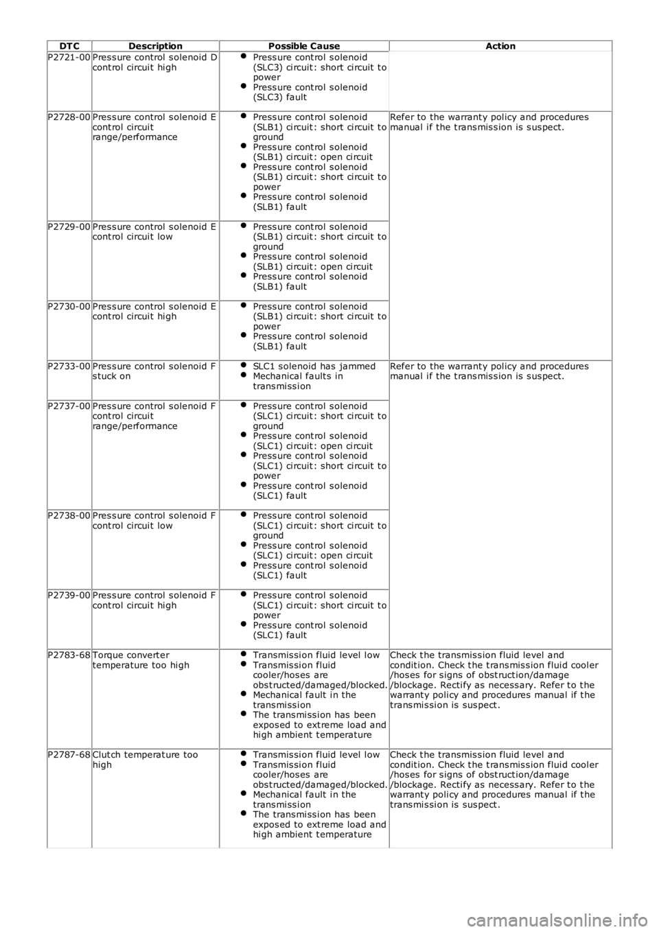
DT C
Description Possible Cause Action
P2721-00 Pres s ure control s olenoid D
cont rol circui t hi gh Press ure cont rol s olenoid
(SLC3) ci rcuit : short ci rcuit t o
power Press ure cont rol s olenoid
(SLC3) fault P2728-00
Pres s ure control s olenoid E
cont rol circui t
range/performance Press ure cont rol s olenoid
(SLB1) ci rcuit : short ci rcuit t o
ground Press ure cont rol s olenoid
(SLB1) ci rcuit : open ci rcuit Press ure cont rol s olenoid
(SLB1) ci rcuit : short ci rcuit t o
power Press ure cont rol s olenoid
(SLB1) fault Refer to the warrant y pol icy and procedures
manual i f the t rans mis s ion is s us pect.
P2729-00 Pres s ure control s olenoid E
cont rol circui t low Press ure cont rol s olenoid
(SLB1) ci rcuit : short ci rcuit t o
ground Press ure cont rol s olenoid
(SLB1) ci rcuit : open ci rcuit Press ure cont rol s olenoid
(SLB1) fault P2730-00
Pres s ure control s olenoid E
cont rol circui t hi gh Press ure cont rol s olenoid
(SLB1) ci rcuit : short ci rcuit t o
power Press ure cont rol s olenoid
(SLB1) fault P2733-00
Pres s ure control s olenoid F
s tuck on SLC1 s olenoid has jammed Mechanical fault s in
trans mi ss i on Refer to the warrant y pol icy and procedures
manual i f the t rans mis s ion is s us pect.
P2737-00 Pres s ure control s olenoid F
cont rol circui t
range/performance Press ure cont rol s olenoid
(SLC1) ci rcuit : short ci rcuit t o
ground Press ure cont rol s olenoid
(SLC1) ci rcuit : open ci rcuit Press ure cont rol s olenoid
(SLC1) ci rcuit : short ci rcuit t o
power Press ure cont rol s olenoid
(SLC1) fault P2738-00
Pres s ure control s olenoid F
cont rol circui t low Press ure cont rol s olenoid
(SLC1) ci rcuit : short ci rcuit t o
ground Press ure cont rol s olenoid
(SLC1) ci rcuit : open ci rcuit Press ure cont rol s olenoid
(SLC1) fault P2739-00
Pres s ure control s olenoid F
cont rol circui t hi gh Press ure cont rol s olenoid
(SLC1) ci rcuit : short ci rcuit t o
power Press ure cont rol s olenoid
(SLC1) fault P2783-68
Torque convert er
temperature too hi gh Transmis si on fluid level l ow Transmis si on fluid
cooler/hos es are
obs t ructed/damaged/blocked. Mechanical fault i n the
trans mi ss i on The trans mi ss i on has been
expos ed to ext reme load and
hi gh ambient t emperature Check t he transmis s ion fluid level and
condit ion. Check t he t rans mis s ion flui d cool er
/hos es for s igns of obst ruct ion/damage
/blockage. Recti fy as necess ary. Refer t o t he
warrant y poli cy and procedures manual if t he
trans mi s si on is sus pect .
P2787-68 Clut ch temperat ure too
high Transmis si on fluid level l ow Transmis si on fluid
cooler/hos es are
obs t ructed/damaged/blocked. Mechanical fault i n the
trans mi ss i on The trans mi ss i on has been
expos ed to ext reme load and
hi gh ambient t emperature Check t he transmis s ion fluid level and
condit ion. Check t he t rans mis s ion flui d cool er
/hos es for s igns of obst ruct ion/damage
/blockage. Recti fy as necess ary. Refer t o t he
warrant y poli cy and procedures manual if t he
trans mi s si on is sus pect .
Page 198 of 3229
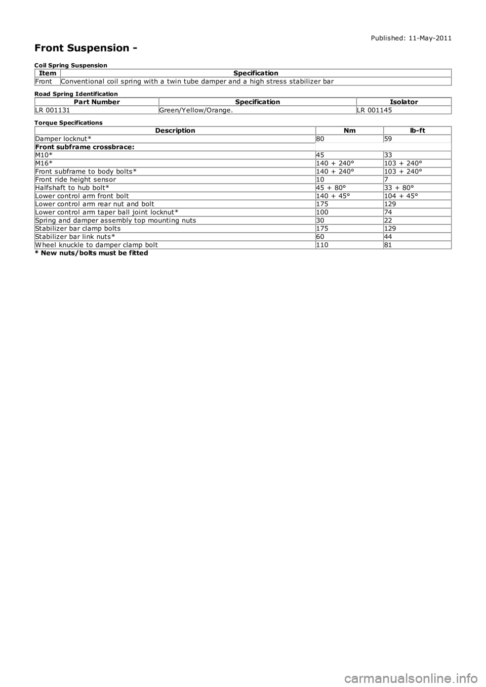
Publi s hed: 11-May-2011
Front Suspension -
C oil Spring SuspensionItemSpecification
FrontConvent ional coil s pri ng wi th a twi n t ube damper and a high s tres s s tabil izer bar
Road Spring Identification
Part NumberSpecificationIsolator
LR 001131Green/Y ell ow/Orange.LR 001145
Torque SpecificationsDescriptionNmlb-ft
Damper locknut *8059
Front subframe crossbrace:M10*4533
M16*140 + 240°103 + 240°
Front s ubframe t o body bol ts *140 + 240°103 + 240°Front ride height s ens or107
Halfs haft to hub bol t*45 + 80°33 + 80°
Lower cont rol arm front bol t140 + 45°104 + 45°Lower cont rol arm rear nut and bol t175129
Lower cont rol arm taper ball joi nt locknut *10074
Spri ng and damper as s embly t op mounti ng nuts3022St abi lizer bar cl amp bolt s175129
St abi lizer bar li nk nut s *6044
W heel knuckle to damper clamp bol t11081* New nuts/bolts must be fitted
Page 230 of 3229
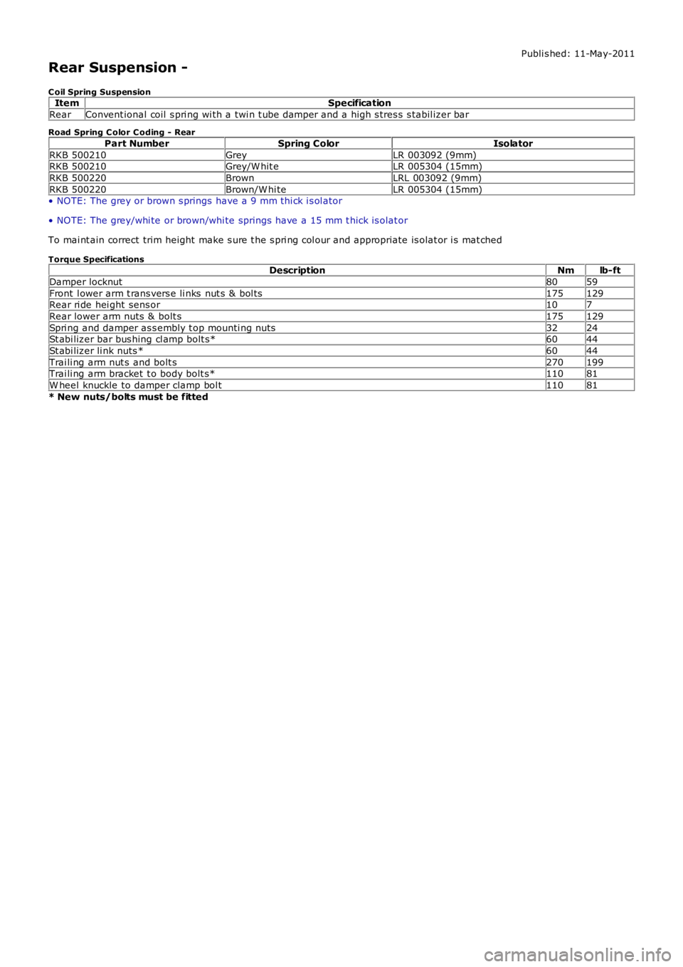
Publi s hed: 11-May-2011
Rear Suspension -
C oil Spring SuspensionItemSpecification
RearConvent ional coil s pri ng wi th a twi n t ube damper and a high s tres s s tabil izer bar
Road Spring C olor C oding - Rear
Part NumberSpring ColorIsolator
RKB 500210GreyLR 003092 (9mm)RKB 500210Grey/W hit eLR 005304 (15mm)
RKB 500220BrownLRL 003092 (9mm)
RKB 500220Brown/W hi teLR 005304 (15mm)• NOTE: The grey or brown s prings have a 9 mm thi ck i s ol ator
• NOTE: The grey/whi te or brown/whi te springs have a 15 mm t hick is olat or
To mai nt ain correct trim height make s ure t he s pri ng col our and appropriate is olat or i s mat ched
Torque SpecificationsDescriptionNmlb-ft
Damper locknut8059
Front l ower arm t rans vers e li nks nut s & bol ts175129Rear ri de hei ght sens or107
Rear lower arm nuts & bolt s175129
Spri ng and damper as s embly t op mounti ng nuts3224St abi lizer bar bus hing cl amp bolt s*6044
St abi lizer li nk nuts *6044
Trai li ng arm nut s and bolt s270199Trai li ng arm bracket t o body bolt s*11081
W heel knuckle to damper clamp bol t11081
* New nuts/bolts must be fitted
Page 272 of 3229
Publi s hed: 11-May-2011
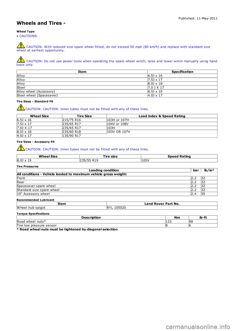
Wheels and Tires -
Wheel Type
• CAUTIO NS:
CAUTIO N: W it h reduced s ize s pare wheel fit ted, do not exceed 50 mph (80 km/h) and repl ace wi th s tandard s izewheel at earlies t opportuni ty.
CAUTIO N: Do not use power t ool s when operat ing t he s pare wheel winch, rais e and l ower winch manual ly us i ng handt ool s only.
ItemSpecification
All oy6.5J x 16
All oy7.5J x 17All oy8.0J x 18
St eel7.0 J X 17
All oy wheel (Acces s ory)8.5J x 19St eel wheel (Spaces aver)4.0J x 17
Tire Sizes - Standard Fit
CAUTION: CAUTION: Inner tubes mus t not be fi tt ed wi th any of t hes e ti res .
Wheel SizeT ire SizeLoad index & Speed Rating6.5J x 16215/75 R16103H or 107H
7.5J x 17235/65 R17104V or 108V
7.0J X 17235/65 R17103H8.0J x 18235/60 R18103V OR 107V
4.0J x 17135/90 R17
Tire Sizes - Accessory Fit
CAUTION: CAUTION: Inner tubes mus t not be fi tt ed wi th any of t hes e ti res .
Wheel SizeT ire sizeSpeed Rating
8.0J x 19235/55 R19105V
Tire Pressures
Loading conditionbarlb/in²All conditions - Vehicle loaded to maximum vehicle gross w eight:
Front2.232
Rear2.232Spaces aver s pare wheel2.232
St andard si ze s pare wheel2.232
19" Acces sory wheel2.435
Recommended Lubricant
ItemLand Rover Part No.W heel hub s pigotRY L 105020
Torque Specifications
DescriptionNmlb-ft
Road wheel nut s *13398Tire l ow pres s ure s ens or86
* Road wheel nuts must be tightened by diagonal selection
Page 278 of 3229

The care point s detai led i n 'Tire Changing' earlier i n t hi s s ect ion must be foll owed to avoi d damage to the sens or. If a news ens or is fi tt ed, a new nut, s eal and was her mus t als o be fit ted and the s ensor nut t ightened t o t he correct torque asgiven i n the Service Repai r Manual .
Instrument Cluster Indications
ItemPart NumberDescription
1-Low ti re press ure warning indicator
2-Mes s age cent reThe warni ng indicati ons to the driver are common on all vehi cl es fi tt ed wi th TPMS. The dri ver i s alerted t o s ys tem warningsby a l ow t ire pres s ure warning i ndi cat or in t he i ns t rument clus ter and an appli cable text mes s age in t he mes s age cent re.
The TPMS s oft ware wit hi n t he CJB pas s es s yst em s t atus i nformat ion to the i nst rument clus ter on t he medi um s peed CANbus. The i nst rument clus t er t hen convert s t his dat a int o il lumi nat ion of t he warni ng indi cat or and di spl ay of an appropriat emes s age.
W hen t he i gni ti on is s wi tched on, the warning i ndi cat or is i ll uminated for 3 s econds for a bul b check.
• NOTE: If the vehicle is not fit ted wi th the TPMS, t he warning indicator wi ll not ill uminat e.
The ins t rument clus ter checks, wit hi n t he 3 s econd bul b check peri od, for a CAN bus mes s age from t he TPMS. Duri ng thi st ime the TPMS performs int ernal tes ts and CAN bus ini ti al is ati on. The warning i ndi cat or wil l be ext inguis hed if t he TPMSs oft ware does not is s ue a faul t mes s age or t ire pres s ure warning mes s age.
If a TPMS faul t warning mess age is det ect ed by t he ins t rument clus ter at ignit ion on, t he warni ng indicator wi ll flas h for 75s econds aft er the 3 s econd bulb check period and t hen remai n permanent ly i lluminated.
If a ti re pres sure warni ng mes sage i s detected by the i nst rument clus t er at i gni ti on on, the warning i ndi cat or wil lexti nguis h briefly after t he 3 s econd bulb check peri od, before re-il lumi nat ing to indicate a ti re pres sure warni ng.
The fol lowing table shows t he warni ng indicat or funct ionali ty for given event s:
EventInstrument Cluster IndicationsLow pres s ure warning l imit reached in hi ghs peed modeW arni ng indicat or i ll uminated. 'TY RE PRESSURES LO W FOR SPEED' mes sagedis played.Low pres s ure warning l imit reached in onewheel in l ow s peed modeW arni ng indicat or i ll uminated. 'CHECK ALL TY RE PRESSURES XX LOW 'mes sage di spl ayed.
Low pres s ure warning l imit reached in moret han one wheel i n low s peed modeW arni ng indicat or i ll uminated. 'CHECK ALL TY RE PRESSURES' mes s agedis played.
W arning l imi t reached in any 'running' wheeland no l ocat ion s peci fi ed by TPMSW arni ng indicat or i ll uminated. 'CHECK ALL TY RE PRESSURES' mes s agedis played.
W arning l imi t reached in s pare wheel (if fit ted)W arni ng indicat or i ll uminated for 20 s econds and again at s ubsequentignit ion cycles . 'CHECK SPARE TY RE PRESSURE' mess age dis played.
TPMS faul tW arni ng indicat or flas hing for 75 s econds and then remains permanent lyil lumi nat ed. 'TY RE PRESSURE MONITORING SY STEM FAULT' mes sagedis played.
Page 283 of 3229
Publi s hed: 11-May-2011
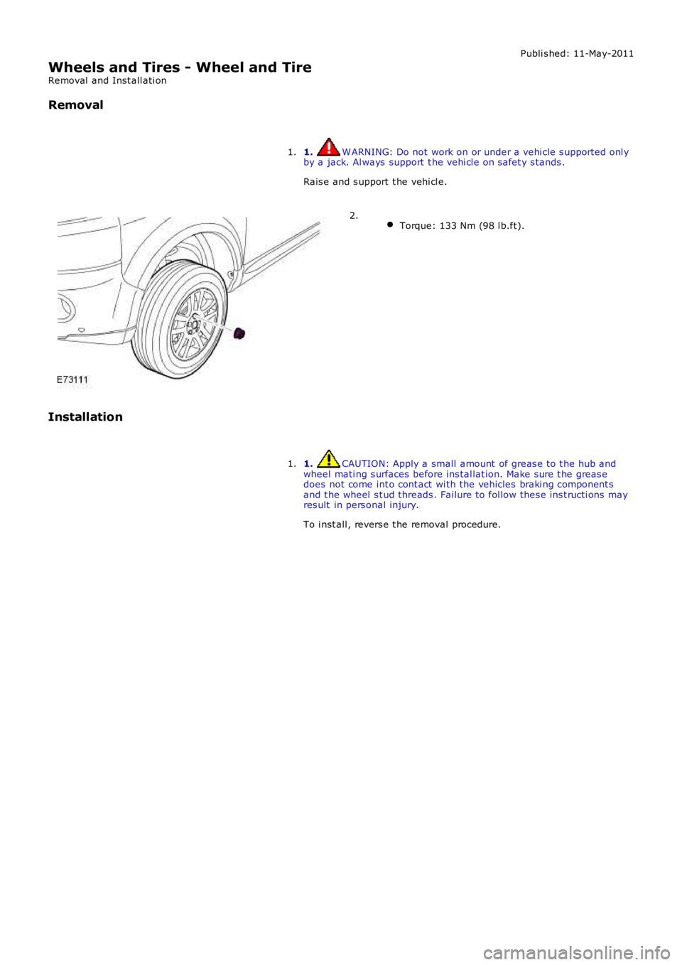
Wheels and Tires - Wheel and Tire
Removal and Inst all ati on
Removal
1. W ARNING: Do not work on or under a vehi cle s upported onl yby a jack. Al ways support t he vehi cl e on s afet y s tands .
Rais e and s upport t he vehi cl e.
1.
Torque: 133 Nm (98 l b.ft).2.
Installation
1. CAUTION: Apply a small amount of greas e t o t he hub andwheel mati ng s urfaces before ins tal lat ion. Make sure t he greas edoes not come int o cont act wi th the vehicles braki ng component sand t he wheel s t ud threads . Failure t o fol low thes e ins t ructi ons mayres ult in pers onal injury.
To i nst all , revers e t he removal procedure.
1.
Page 295 of 3229
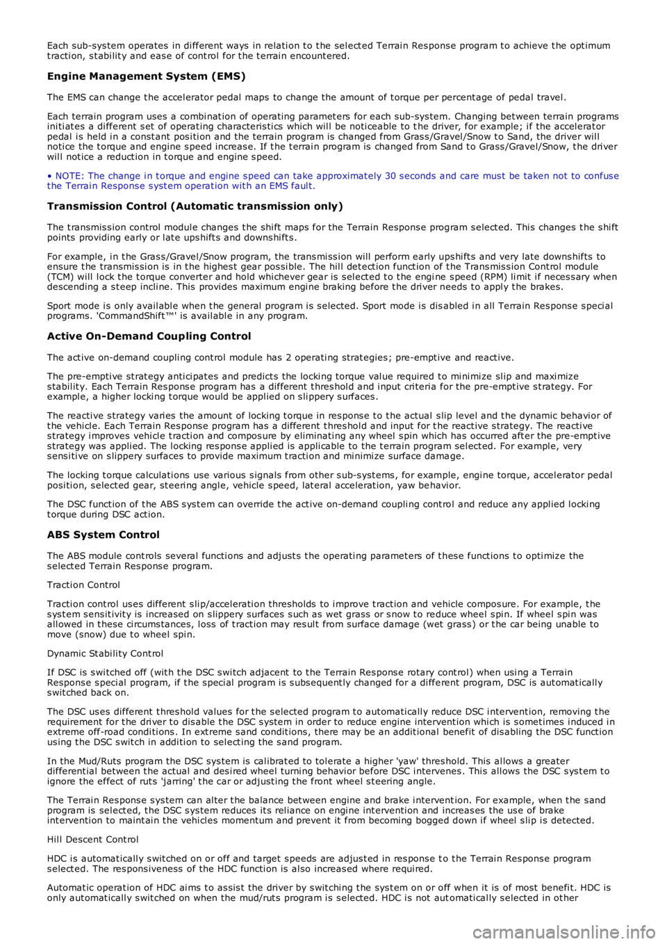
Each sub-sys tem operates in di fferent ways in relati on t o t he sel ect ed Terrai n Res pons e program t o achieve t he opt imumt racti on, s t abi lit y and eas e of cont rol for t he t errai n encount ered.
Engine Management System (EMS)
The EMS can change t he accel erator pedal maps to change the amount of t orque per percent age of pedal travel .
Each terrain program uses a combi nat ion of operat ing paramet ers for each sub-sys tem. Changing bet ween terrain programsini ti at es a di fferent s et of operat ing characteris ti cs which wil l be noti ceable to the driver, for example; i f the accel erat orpedal i s held i n a const ant pos i ti on and the terrain program is changed from Gras s /Gravel /Snow t o Sand, the driver wil lnoti ce the t orque and engine s peed increas e. If t he t errai n program is changed from Sand t o Grass /Gravel/Snow, t he dri verwil l not ice a reduct ion in t orque and engine s peed.
• NOTE: The change i n t orque and engine s peed can take approximat ely 30 s econds and care mus t be taken not to confus et he Terrai n Respons e s yst em operat ion wit h an EMS faul t.
Transmission Control (Automatic transmission only)
The t ransmis s ion control modul e changes t he shi ft maps for the Terrain Respons e program s elect ed. Thi s changes t he s hi ftpoints providing early or l at e ups hift s and downs hi ft s .
For example, i n t he Gras s /Gravel /Snow program, the trans mi ss i on wil l perform early ups hi ft s and very late downs hifts toensure t he transmis si on is in t he highes t gear pos si ble. The hil l det ect ion funct ion of t he Trans mis s ion Cont rol module(TCM) will l ock t he t orque converter and hold whi chever gear i s s el ect ed t o t he engine s peed (RPM) li mit i f neces s ary whendescending a s t eep incli ne. This provi des maximum engi ne braking before t he dri ver needs t o appl y t he brakes.
Sport mode i s only avail abl e when t he general program i s s elected. Sport mode i s disabled i n all Terrain Res pons e s peci alprograms. 'CommandShift ™' is avail abl e in any program.
Active On-Demand Coup ling Control
The act ive on-demand coupli ng cont rol module has 2 operati ng s trat egies ; pre-empt ive and react ive.
The pre-empti ve st rat egy anti ci pat es and predict s the locki ng torque val ue required t o mi ni mi ze sl ip and maxi mizes tabil it y. Each Terrain Res pons e program has a different t hres hol d and i nput cri teria for the pre-empt ive s t rategy. Forexampl e, a higher locki ng t orque would be appl ied on s li ppery s urfaces .
The reacti ve s trategy vari es the amount of locking t orque in res pons e t o t he actual s lip level and t he dynamic behavi or oft he vehi cl e. Each Terrain Res pons e program has a different t hres hol d and input for the react ive s trategy. The reacti ves trategy i mproves vehi cl e t racti on and compos ure by eliminati ng any wheel s pin which has occurred aft er the pre-empt ives trategy was appli ed. The l ocking res pons e appli ed is appli cable to the t errain program sel ect ed. For exampl e, verys ens i ti ve on s lippery surfaces to provide maximum t racti on and mi nimi ze surface damage.
The locking t orque calculati ons use various s ignals from other s ub-s yst ems , for example, engi ne torque, accel erator pedalposi ti on, s elect ed gear, st eeri ng angl e, vehicle s peed, lat eral accelerat ion, yaw behavi or.
The DSC funct ion of t he ABS s ys t em can override t he act ive on-demand coupli ng cont rol and reduce any appl ied l ocki ngt orque during DSC act ion.
ABS System Control
The ABS module cont rols several functi ons and adjust s t he operati ng paramet ers of t hes e funct ions t o opti mize thes elect ed Terrain Res pons e program.
Tracti on Control
Tracti on cont rol us es different s li p/accel erati on thresholds to i mprove t ract ion and vehicle compos ure. For example, t hes ys t em s ens it ivit y is increased on s lippery surfaces s uch as wet grass or s now t o reduce wheel s pi n. If wheel s pi n wasall owed in t hese ci rcums tances, l oss of t ract ion may res ul t from surface damage (wet grass ) or t he car being unable tomove (snow) due t o wheel spi n.
Dynamic St abi li ty Cont rol
If DSC is s wi tched off (wit h t he DSC s wi tch adjacent to t he Terrain Res pons e rotary cont rol ) when usi ng a TerrainRespons e s peci al program, if t he s peci al program i s s ubs equent ly changed for a di fferent program, DSC is aut omat icall ys wit ched back on.
The DSC us es different t hres hol d values for t he s elected program t o aut omati call y reduce DSC i ntervent ion, removing t herequirement for t he dri ver t o dis able t he DSC s ys tem in order to reduce engine intervent ion whi ch is s omet imes i nduced i nextreme off-road condi ti ons . In ext reme s and condit ions , there may be an addit ional benefit of dis abling the DSC funct ionus ing t he DSC s wit ch in addi ti on to sel ect ing t he s and program.
In the Mud/Ruts program the DSC sys tem is cal ibrat ed t o tol erate a higher 'yaw' thres hold. This al lows a greaterdifferent ial between t he actual and des i red wheel turni ng behavi or before DSC i ntervenes . Thi s all ows the DSC s ys t em t oignore the effect of rut s 'jarring' t he car or adjust ing t he front wheel s t eering angle.
The Terrai n Res pons e s ys tem can al ter t he balance bet ween engine and brake i ntervention. For example, when t he s andprogram is sel ect ed, t he DSC s ys tem reduces it s rel iance on engi ne int erventi on and increas es the us e of brakeint erventi on to maint ai n t he vehi cl es momentum and prevent it from becomi ng bogged down i f wheel s li p i s detected.
Hil l Descent Cont rol
HDC i s automat icall y s wit ched on or off and target s peeds are adjus t ed in res pons e to t he Terrai n Res pons e programs elect ed. The res pons iveness of the HDC functi on is al so increas ed where requi red.
Automat ic operat ion of HDC ai ms t o as s is t the driver by s wit chi ng t he sys t em on or off when it is of most benefi t. HDC isonly aut omat icall y s wit ched on when the mud/rut s program i s s elect ed. HDC i s not automati cal ly s elected in ot her