2006 LAND ROVER FRELANDER 2 heating
[x] Cancel search: heatingPage 104 of 3229
Publi shed: 06-Jul-2011
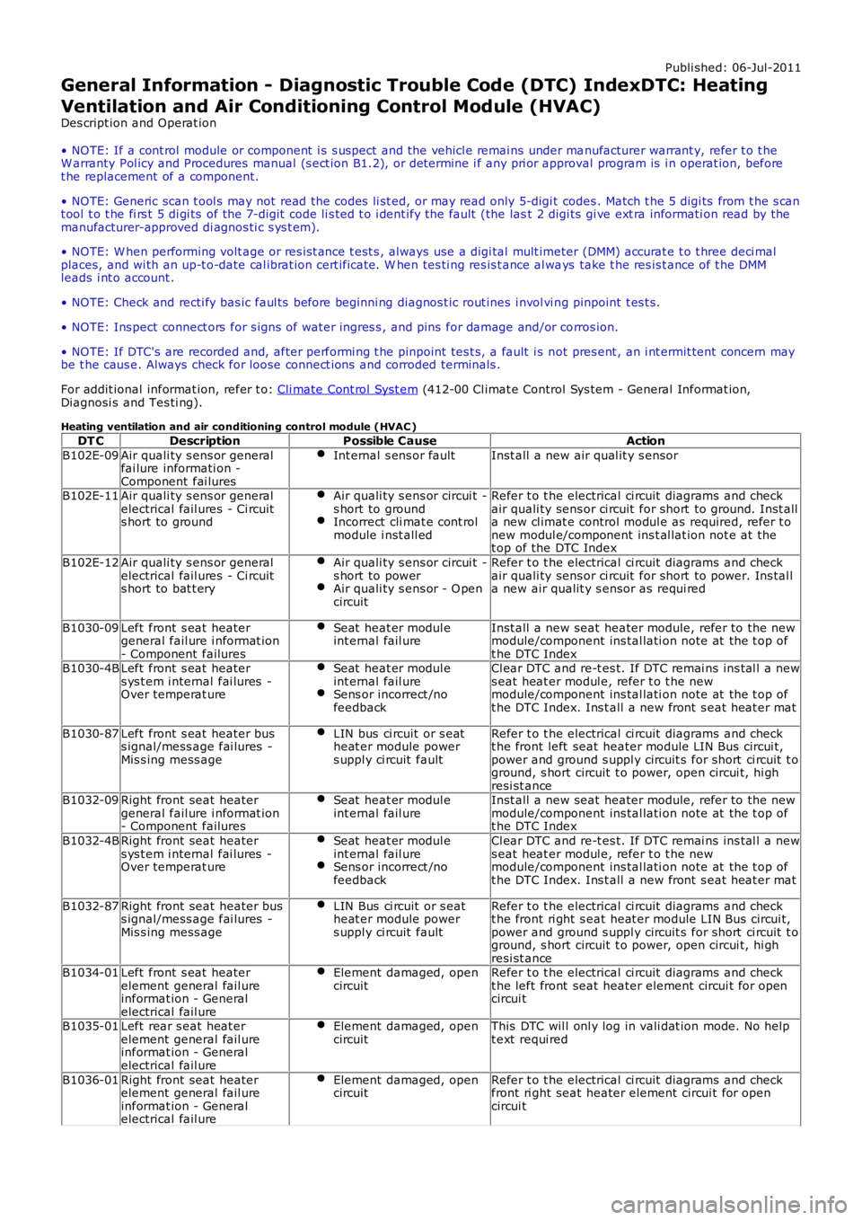
General Information - Diagnostic Trouble Code (DTC) IndexDTC: Heating
Ventilation and Air Conditioning Control Module (HVAC)
Des cript ion and Operat ion
• NOTE: If a cont rol module or component i s s uspect and the vehicl e remai ns under manufacturer warrant y, refer t o t heW arranty Pol icy and Procedures manual (s ect ion B1.2), or determine i f any pri or approval program is i n operat ion, beforet he replacement of a component.
• NOTE: Generic scan t ool s may not read the codes li st ed, or may read only 5-digi t codes . Match t he 5 digi ts from t he s cant ool t o t he fi rs t 5 di gi ts of the 7-digit code li s ted t o i dent ify the fault (the last 2 digi ts gi ve ext ra informati on read by themanufacturer-approved di agnos ti c s ys t em).
• NOTE: W hen performing volt age or res is t ance t est s , always use a digi tal mult imeter (DMM) accurat e t o t hree deci malplaces, and wi th an up-t o-date cal ibrat ion cert ificate. W hen tes ti ng res is t ance al ways take t he res is t ance of t he DMMleads i nt o account .
• NOTE: Check and recti fy bas ic faul ts before beginni ng diagnos t ic rout ines i nvol vi ng pinpoint t es t s.
• NOTE: Ins pect connect ors for s igns of water ingres s , and pins for damage and/or corros ion.
• NOTE: If DTC's are recorded and, after performi ng t he pinpoint tes t s, a fault i s not pres ent , an i nt ermit tent concern maybe t he caus e. Always check for loose connect ions and corroded terminals .
For addit ional informat ion, refer t o: Cli mate Cont rol Syst em (412-00 Cl imat e Control Sys tem - General Informat ion,Diagnosi s and Tes ti ng).
Heating ventilation and air conditioning control module (HVAC )
DT CDescriptionPossible CauseAction
B102E-09Air quali ty s ens or generalfai lure informati on -Component fai lures
Int ernal s ens or faultInst all a new air qual it y s ensor
B102E-11Air quali ty s ens or generalelectrical fail ures - Ci rcuits hort to ground
Air quali ty s ens or circui t -s hort to groundIncorrect cli mat e cont rolmodule i nst all ed
Refer t o t he electrical ci rcuit diagrams and checkair quali ty sens or ci rcuit for short to ground. Inst alla new cl imat e control modul e as required, refer t onew modul e/component ins t al lat ion not e at thet op of the DTC Index
B102E-12Air quali ty s ens or generalelectrical fail ures - Ci rcuits hort to bat t ery
Air quali ty s ens or circui t -s hort to powerAir quali ty s ens or - O pencircuit
Refer t o t he electrical ci rcuit diagrams and checkair quali ty sens or ci rcuit for short to power. Ins tal la new air qualit y s ensor as requi red
B1030-09Left front s eat heatergeneral fail ure i nformat ion- Component failures
Seat heat er modul eint ernal fail ureInst all a new seat heater module, refer to the newmodule/component ins tal lati on note at the t op oft he DTC IndexB1030-4BLeft front s eat heaters ys t em i nternal fai lures -Over temperat ure
Seat heat er modul eint ernal fail ureSens or incorrect /nofeedback
Cl ear DTC and re-t es t. If DTC remai ns ins tal l a news eat heat er modul e, refer t o t he newmodule/component ins tal lati on note at the t op oft he DTC Index. Ins t all a new front s eat heat er mat
B1030-87Left front s eat heater buss ignal/mess age fai lures -Mis s ing mess age
LIN bus ci rcuit or s eatheat er module powers uppl y ci rcuit fault
Refer t o t he electrical ci rcuit diagrams and checkt he front left seat heater module LIN Bus circui t,power and ground s uppl y circuit s for short ci rcuit t oground, s hort circuit t o power, open circui t, hi ghresi st anceB1032-09Right front seat heatergeneral fail ure i nformat ion- Component failures
Seat heat er modul eint ernal fail ureInst all a new seat heater module, refer to the newmodule/component ins tal lati on note at the t op oft he DTC Index
B1032-4BRight front seat heaters ys t em i nternal fai lures -Over temperat ure
Seat heat er modul eint ernal fail ureSens or incorrect /nofeedback
Cl ear DTC and re-t es t. If DTC remai ns ins tal l a news eat heat er modul e, refer t o t he newmodule/component ins tal lati on note at the t op oft he DTC Index. Ins t all a new front s eat heat er mat
B1032-87Right front seat heater buss ignal/mess age fai lures -Mis s ing mess age
LIN Bus ci rcuit or s eatheat er module powers uppl y ci rcuit fault
Refer t o t he electrical ci rcuit diagrams and checkt he front ri ght s eat heat er module LIN Bus circui t,power and ground s uppl y circuit s for short ci rcuit t oground, s hort circuit t o power, open circui t, hi ghresi st anceB1034-01Left front s eat heaterelement general fail ureinformat ion - Generalelectrical fail ure
Element damaged, opencircuitRefer t o t he electrical ci rcuit diagrams and checkt he left front seat heater element circui t for opencircui t
B1035-01Left rear s eat heat erelement general fail ureinformat ion - Generalelectrical fail ure
Element damaged, opencircuitThis DTC wil l onl y log in vali dat ion mode. No hel pt ext requi red
B1036-01Right front seat heaterelement general fail ureinformat ion - Generalelectrical fail ure
Element damaged, opencircuitRefer t o t he electrical ci rcuit diagrams and checkfront ri ght seat heater element circui t for opencircui t
Page 1635 of 3229
Publi s hed: 11-May-2011
Climate Control - Heating and Ventilation
Des cript ion and Operat ion
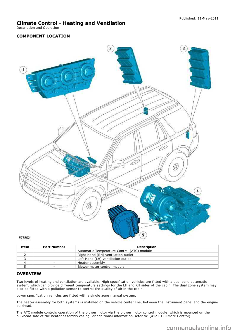
COMPONENT LOCATION
ItemPart NumberDescription1-Automat ic Temperat ure Cont rol (ATC) modul e
2-Right Hand (RH) vent il at ion out let
3-Left Hand (LH) vent il at ion out let4-Heater as s embl y
5-Blower mot or cont rol module
OVERVIEW
Two l evels of heat ing and venti lati on are avai lable. High s pecifi cat ion vehicles are fit ted wit h a dual zone aut omati cs ys t em, which can provide di fferent temperature s et t ings for t he LH and RH si des of the cabin. The dual zone s yst em mayals o be fit t ed wit h a pol luti on s ens or t o cont rol t he qual it y of air in the cabin.
Lower s pecifi cat ion vehicles are fit ted wit h a s ingle zone manual s yst em.
The heat er ass embl y for both sys t ems is ins tall ed on t he vehi cl e cent er li ne, bet ween the i nst rument panel and the enginebulkhead.
The ATC module cont rols operat ion of t he blower mot or vi a t he blower mot or control modul e, whi ch is mount ed on t hebulkhead si de of the heat er as s embly cas ing.For addi ti onal i nformat ion, refer to: (412-01 Cli mate Cont rol )
Page 1737 of 3229
Publi shed: 26-Jul-2011
Auxiliary Heating - Fuel Fired Booster Heater
Diagnosi s and Tes ti ng
Overview
For informati on on t he des cri pti on and operati on of the s ys tem, refer t o s ect ion 412-02 -REFER to:
Fuel Fired Boos t er Heat er (412-02B Auxil iary Cli mate Cont rol, Des cri pt ion and Operati on),Fuel Fired Boos t er Heat er (412-02B, Des cript ion and Operat ion),Fuel Fired Boos t er Heat er (412-02B Auxil iary Cli mate Cont rol, Removal and Ins t al lat ion),Fuel Fired Boos t er Heat er Fuel Pump (412-02B Auxili ary Cl imat e Control, Removal and Ins tall ati on),Fuel Fired Boos t er Heat er Cool ant Pump (412-02B Auxil iary Cli mate Cont rol, Removal and Ins t al lat ion),Fuel Fired Boos t er Heat er Glow Pl ug And Burner As sembl y (412-02B Auxi liary Cli mate Cont rol , Removal andIns tal lat ion).Auxi li ary Heat ing i n the works hop manual .
Inspection and Verification
1. Verify t he cus t omer concern.1.
2. Vis ually ins pect for obvious mechani cal or electrical fault s .2.
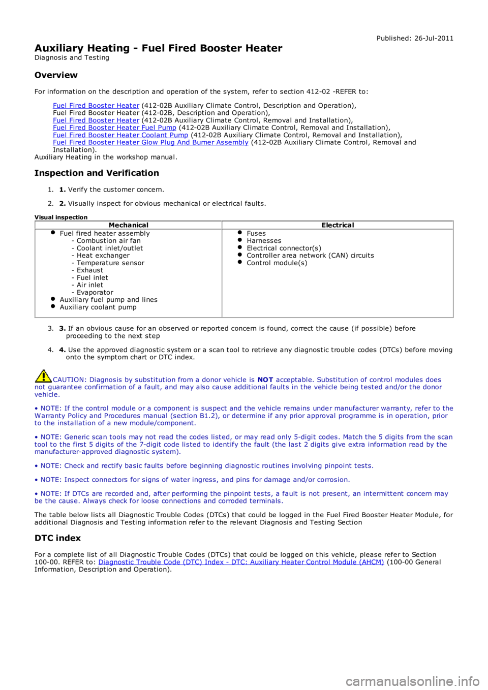
Visual inspectionMechanicalElectrical
Fuel fired heater as sembl y- Combus ti on air fan- Coolant inl et /out let- Heat exchanger- Temperat ure s ens or- Exhaus t- Fuel inlet- Ai r inlet- EvaporatorAuxili ary fuel pump and li nesAuxili ary coolant pump
Fus esHarness esEl ect ri cal connector(s )Cont roll er area network (CAN) ci rcuit sCont rol module(s)
3. If an obvious cause for an obs erved or report ed concern is found, correct t he caus e (if pos s ible) beforeproceeding t o t he next s t ep3.
4. Us e the approved di agnos ti c s ys t em or a s can t ool t o ret rieve any diagnos t ic t rouble codes (DTCs ) before movingont o t he sympt om chart or DTC i ndex.4.
CAUTION: Di agnos is by s ubs ti tut ion from a donor vehicle is NO T acceptabl e. Subs ti tut ion of cont rol modules doesnot guarant ee confirmat ion of a faul t, and may als o caus e addit ional fault s i n t he vehi cl e being t est ed and/or t he donorvehi cl e.
• NOTE: If the control modul e or a component i s s us pect and the vehicle remains under manufacturer warrant y, refer t o theW arranty Pol icy and Procedures manual (s ect ion B1.2), or determine i f any pri or approval programme is in operat ion, pri ort o the ins tall ati on of a new module/component.
• NOTE: Generic scan t ool s may not read the codes li st ed, or may read only 5-digi t codes . Match t he 5 digi ts from t he s cant ool t o t he fi rs t 5 di gi ts of the 7-digit code li s ted t o i dent ify the fault (the last 2 digi ts gi ve ext ra informati on read by themanufacturer-approved di agnos ti c s ys t em).
• NOTE: Check and recti fy bas ic faul ts before beginni ng diagnos t ic rout ines i nvol vi ng pinpoint t es t s.
• NOTE: Ins pect connect ors for s igns of water ingres s , and pins for damage and/or corros ion.
• NOTE: If DTCs are recorded and, aft er performi ng the pi npoi nt tes ts , a fault is not present , an int ermi tt ent concern maybe t he caus e. Always check for loose connect ions and corroded terminals .
The t abl e below l is t s all Diagnos ti c Trouble Codes (DTCs ) t hat could be logged in the Fuel Fi red Boos ter Heater Module, foraddi ti onal Di agnos is and Tes ti ng informat ion refer t o t he relevant Diagnosi s and Test ing Secti on
DTC index
For a compl ete lis t of all Di agnos ti c Trouble Codes (DTCs) t hat could be logged on this vehicle, pleas e refer to Sect ion100-00. REFER t o: Diagnost ic Troubl e Code (DTC) Index - DTC: Auxi li ary Heater Control Modul e (AHCM) (100-00 GeneralInformat ion, Des cript ion and Operat ion).
Page 2163 of 3229
Revers e gear mirror dip i s only avail abl e when memory mi rrors are ins t al led, and revers e gear mi rror di p is enabled wit hint he ins trument cl ust er.
If the driver sel ect s a memory recall funct ion us ing the memory s eat swit ch pack, the driver's memory seat and exteriormemory mi rrors are moved to a s tored memory pos i ti on.For addit ional informat ion, refer t o: Seat s (501-10 Seati ng, Des cript ion and Operat ion).
Mirror Power Fold and Auto Fold Feature
Exteri or mirrors wit h t he power fold/auto fold feature incorporat e a motor located in t he hinge of each ext eri or mirror arm.Operat ion of t he power fold feature is achieved us ing t he exteri or mirror s wit ch pack. Operat ion of t he auto fold feature isachi eved us ing the remote hands et.
The power fold funct ion is acti ve when t he ignit ion i s in power mode 6 (Ignit ion).
Both ext eri or mirrors wil l power fol d when t he mi rror s wi tch pack 'L' and 'R' s wit ches are pres s ed t oget her. Pres s ing t hes wit ches again wil l unfol d t he mi rrors .
W hen t he i ns t rument clus ter i s configured for the aut o fol d feat ure, t he mirrors wi ll fol d in when the remot e hands et lockbutt on is pres sed. The mi rrors wi ll unfold when the vehicl e is unl ocked us ing t he remot e handset unlock butt on.
• NOTE: If the mirrors are folded in usi ng t he mirror s wit ch pack (power fol d) and the vehicle i s t hen locked, s ubs equentunlocki ng of the vehicle wil l not unfol d t he mirrors .
W hen t he remote hands et unl ock but ton i s operated, t he CJB recogni zes t he remote hands et for that vehicle andacknowledges t he request . The door control modul es are connect ed direct ly t o t he AJB for power s uppl y to the ext eriormi rror folding motors.
W hen t he vehicle i s locked the door cont rol modules revers e t he pol ari ty of t he mi rror fold motor, power and groundconnecti ons to operat e t he mi rrors i n t he oppos it e direct ion.
Exterior Mirror Heating
Exteri or mirror heati ng is provi ded wit h heater element s bonded to t he back of the mirror glas s. Power s uppl y for t he mi rrorheat ing el ements i s provided by the corresponding driver or pas s enger door control modul e via the AJB.
The door control modul es receive a power s uppl y from the AJB, and are bot h connected on the medi um s peed CAN bus t ot he ATC module. A ground t erminal from each door control modul e completes the circuit. The ATC modul e automat icall ycont rol s the mirror heati ng functi on whenever the ignit ion i s in power mode 4 (Access ory) and power mode 6 (Igni ti on).For addit ional informat ion, refer t o: Cont rol Component s (412-01 Cli mat e Cont rol , Descripti on and Operat ion).
DRIVER PROXIMITY MIRROR (JAPANESE SPECIFICATION ONLY)
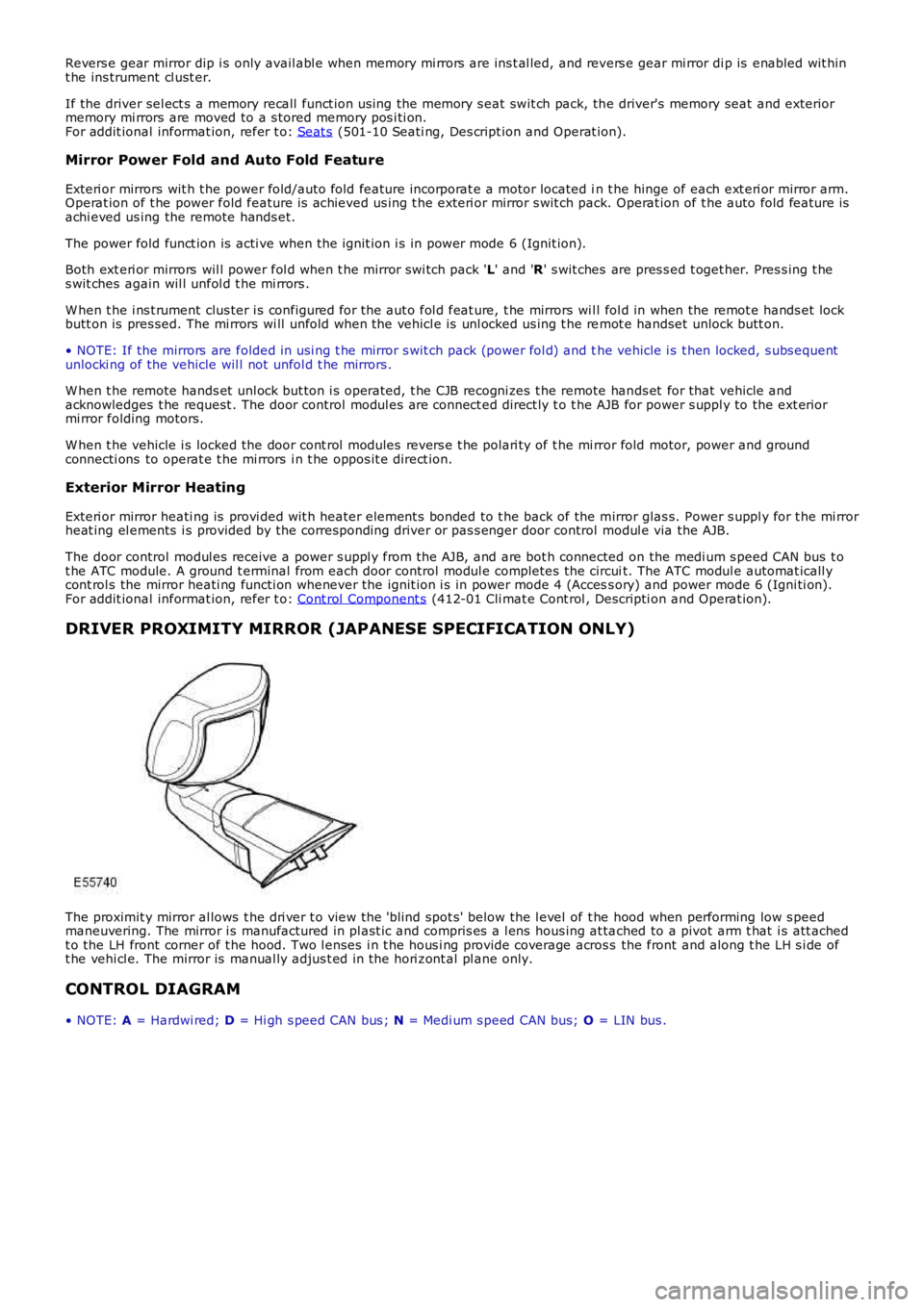
The proximit y mirror al lows t he dri ver t o view the 'blind spot s' below the l evel of t he hood when performing low s peedmaneuvering. The mirror i s manufactured in pl ast ic and compris es a l ens hous ing at tached to a pivot arm t hat i s att achedt o the LH front corner of t he hood. Two l enses i n t he hous i ng provide coverage across the front and along t he LH s i de oft he vehi cl e. The mirror is manual ly adjus t ed in the hori zont al pl ane only.
CONTROL DIAGRAM
• NOTE: A = Hardwi red; D = Hi gh s peed CAN bus ; N = Medi um s peed CAN bus; O = LIN bus .
Page 2179 of 3229
and adopt ed as t he current pos it ions. This wil l al low the relat ive memory posi ti ons to be ret ained wit hout any need t o
recali brate the power s eat modul e.
The power seat module is able to be 'flas hed' for s ervice updates or i nterrogat ed us ing t he Land Rover approved diagnost ic
equi pment.
Up t o 3 di fferent s eat pos it ions are abl e t o be s t ored i n the power s eat modul e. Sea t pos it ions are st ored in memory by
pres s ing t he memory butt on ( M), and t hen 1 of t he 3 memory s tore butt ons ( 1, 2, 3) wi thi n 5 s econds . The memory
butt ons are l ocat ed on t he s wit ch pack. The swit ch pack memory butt ons allow the dri ver t o cont rol t he memory st orage
and recall operat ions for t he s eat and ext erior mi rrors . The s wit ch pack but tons are non-lat chi ng, moment ary act ion
s wit ches .
On vehicles i nst all ed wit h a hi gh-li ne ins t rument clus ter and t he ignit ion s wi tched on, the s eat posi ti on memory s tore
commands are di spl ayed i n t he mes sage center and a si ngl e chime is s ounded to confi r m t he new s eat pos it ion i s s aved.
• NOTE: Low-l ine i nst rument clus ters are not i nst all ed to vehi cl es equi pped wit h a m emory s eat sys t em.
For addit ional informat ion, refer t o: Ins t rument Clus ter (413-01 Inst rument Cl us t er, Des cript ion and Operat ion) /
Informat ion and Mes s age Cent er (413-08 Informat ion and Mes s age Cent er, Des cript ion and Operat ion).
The power seat module provi des the foll owing driver sel ect abl e functi ons: Seat and ext erior mirror memory recall Immediat e s eat adjus t ment.
For furt her operat ing det ail s of the driver sel ect abl e funct ions, refer t o t he s ect i
on 'Principles of Operat ion'.
The act ivi ty of t he s eat is automat icall y monit ored by t he power s eat module. The mo dule wil l react to motors that are not
functi oni ng correct ly t o an operat ion reques t , and will al so aim to reduce power con sumpt ion during peri ods of i nact ivit y.
The power seat module provi des the foll owing automat ic moni toring funct ions : Stal l det ect ion mode Sleep mode
Batt ery moni tor mode.
For furt her operat ing det ail s of the aut omati c monit oring funct ions , refer t o t he s e
ct ion 'Pri nci pl es of Operati on'.
Calibration of Power Seat Module
If the power s eat modul e is replaced in servi ce, t he repl acement module must be cali brat ed usi ng t he Land Rover approved
diagnost ic equipment . The cal ibrat ion routi ne is necess ary for t he power s eat module t o reset t he s eat dat um values .
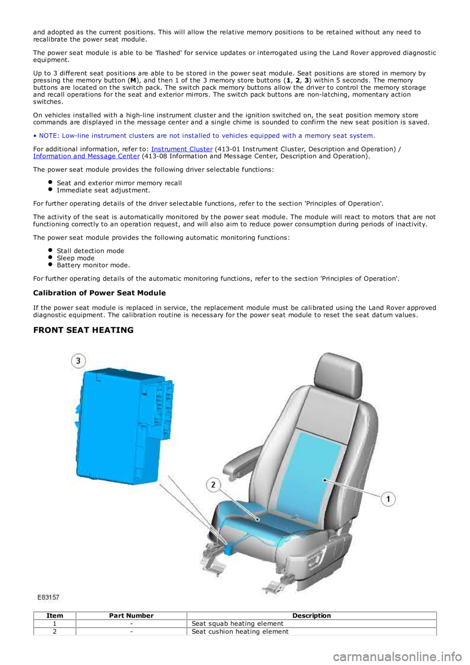
FRONT SEAT HEATING Item
Part Number Description
1 -Seat s quab heat ing el ement
2 -Seat cus hi on heat ing el ement
Page 2184 of 3229
3
-Driver's door control modul e
4 -LH ext erior mirror
5 -Pas senger door control modul e
6 -RH ext eri or mirror
7 -Inst rument clus t er
8 -CJB wi th bat tery-s aver t imer relay
9 -St art cont rol module
10 -AJB
11 -Power operated l umbar support s wi tch
12 -Power operated l umbar support mot or
13 -Driver's power operat ed memory s eat s wi tch pack
14 -Driver's power operat ed memory s eat hei ght mot or
15 -Driver's power s eat module
16 -Driver's power operat ed memory s eat s quab recli ne mot or
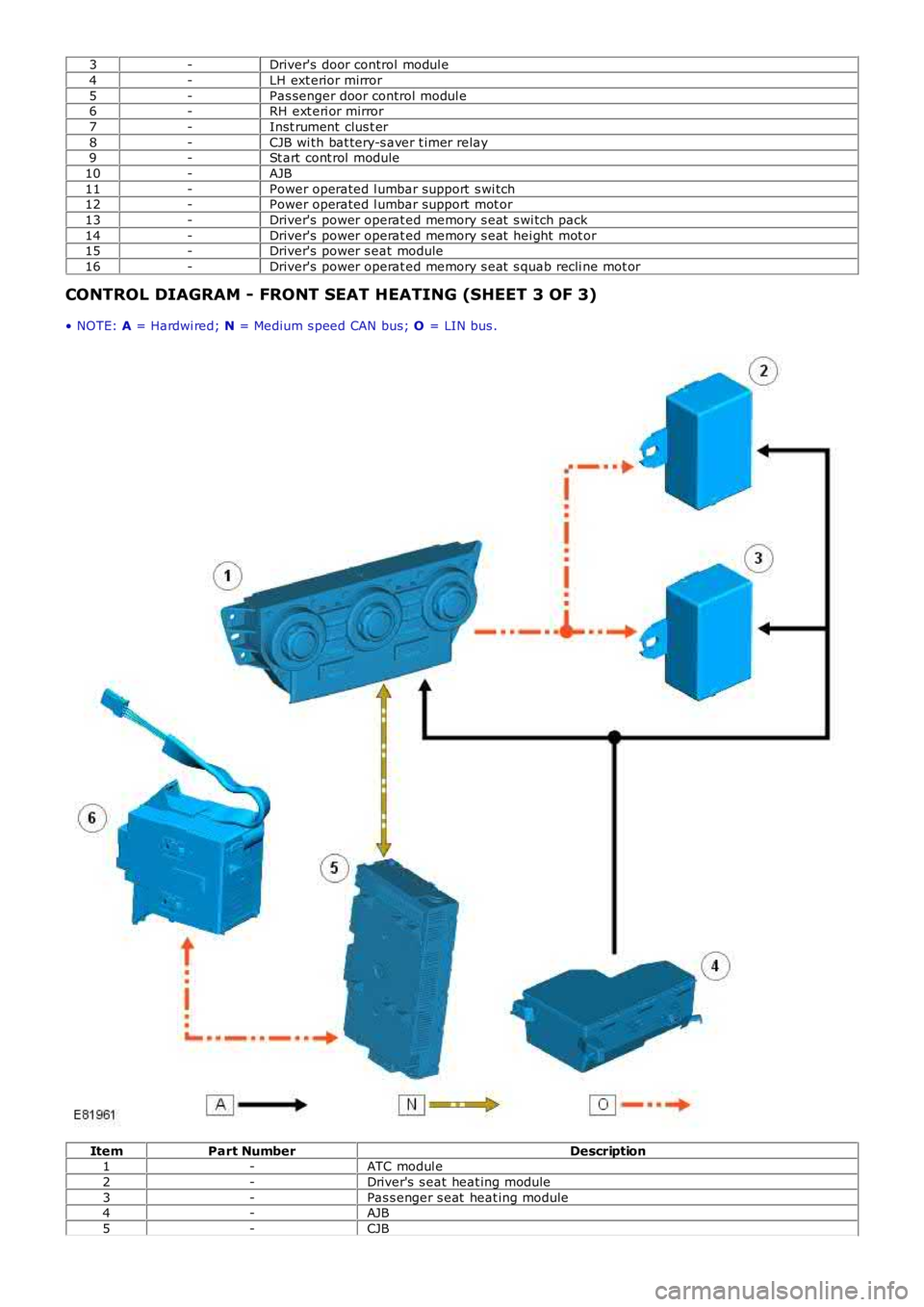
CONTROL DIAGRAM - FRONT SEAT HEATING (SHEET 3 OF 3)
• NOTE: A = Hardwi red; N = Medium s peed CAN bus; O = LIN bus . Item
Part Number Description
1 -ATC modul e
2 -Driver's s eat heat ing module
3 -Pas s enger s eat heat ing module
4 -AJB
5 -CJB
Page 2734 of 3229
14
Quick start
L
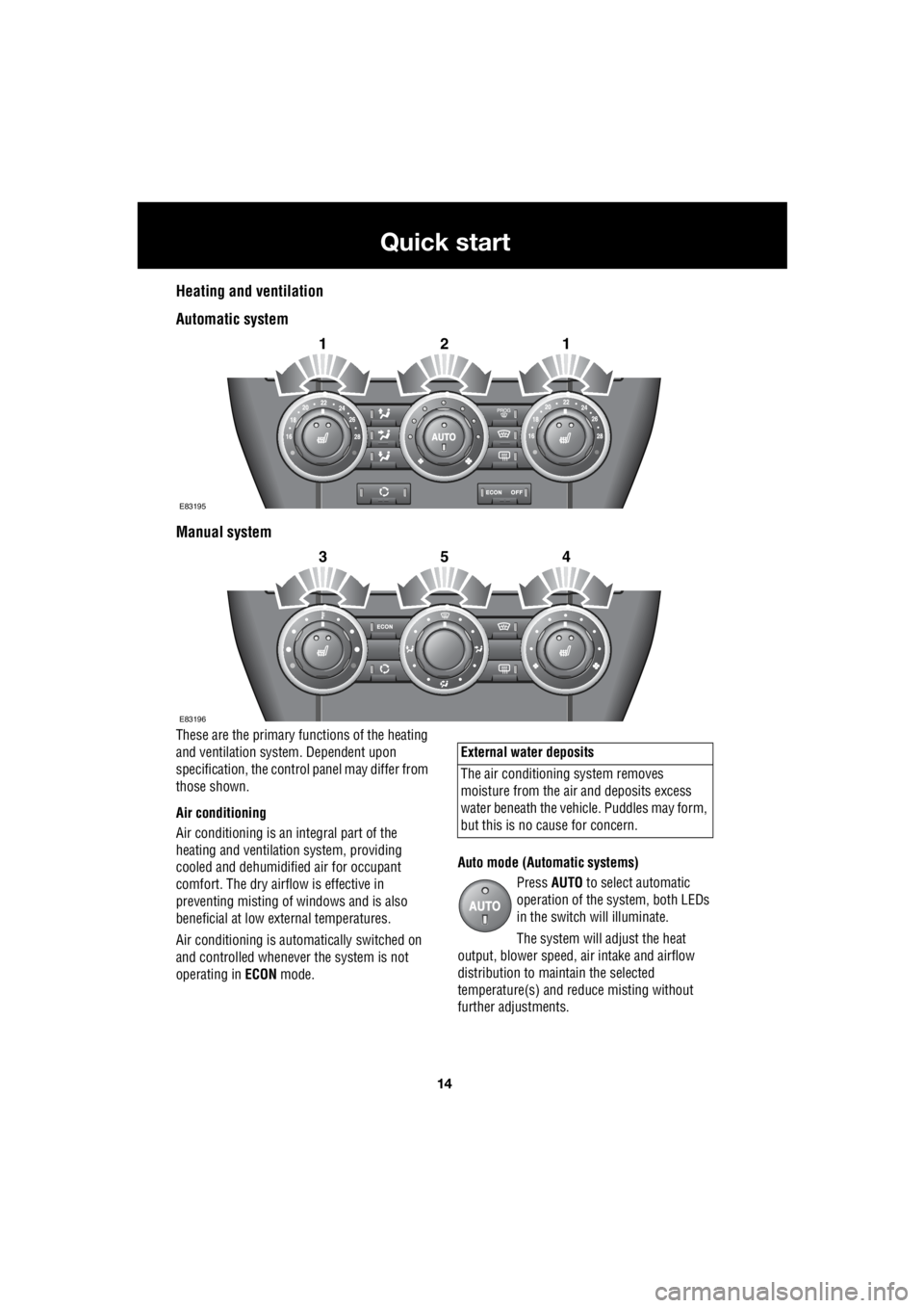
Heating and ventilation
Automatic system
Manual system
These are the primary functions of the heating
and ventilation syst em. Dependent upon
specification, the contro l panel may differ from
those shown.
Air conditioning
Air conditioning is an in tegral part of the
heating and ventilati on system, providing
cooled and dehumidifie d air for occupant
comfort. The dry airflow is effective in
preventing misting of windows and is also
beneficial at low external temperatures.
Air conditioning is automatically switched on
and controlled whenever the system is not
operating in ECON mode. Auto mode (Automatic systems)
Press AUTO to select automatic
operation of the system, both LEDs
in the switch will illuminate.
The system will adjust the heat
output, blower speed, air intake and airflow
distribution to maintain the selected
temperature(s) and re duce misting without
further adjustments.
2121
E83195
2354
E83196
External water deposits
The air conditioning system removes
moisture from the ai r and deposits excess
water beneath the vehicl e. Puddles may form,
but this is no cause for concern.
Page 2818 of 3229
Instruments
98
L
Tachometer
Indicates engine spee d in revolutions per
minute (RPM) x 1000.
Temperature gauge
If the pointer moves onto the red line and the
red warning indicator illu minates severe engine
damage can occur.
If the engine overheats, stop the vehicle as
soon as safety pe rmits. Switch the engine off
and allow it to cool down. If the problem
reoccurs, seek qualified assistance before
continuing.
Note: If engine temperatur e rises to the point
where overheating may occur, there may be a
noticeable reduction in engine power, and the
air conditioning may cease operation. This is a
normal operating strate gy to reduce load on
the engine and assist with cooling.
Fuel gauge
Once the fuel level has dropped to the point
where the range is approximately 80 km (50
miles) the low fuel warning indicator will
illuminate.
As a reminder for the location of the fuel filler,
there is an arrow next to the fuel pump symbol
which points to the releva nt side of the vehicle.
Speedometer
Indicates road speed. Odometer
Indicates the total distance which the vehicle
has travelled.
Trip recorder
Indicates the distance travelled since the last
reset, and can be used to measure the distance
of individual journeys.
Trip recorder reset button
Resets the distance shown on the trip recorder
to zero.
Note: Once the trip recorder has been reset to
zero, the previously recorded distance will be
lost.
Gear selector mode and positiondisplay
Displays the currently selected gear on
vehicle's fitted with automatic transmission.
Main message centre
Displays warning, and information messages.
See INFORMATION MESSAGES (page 99).
Warning indicator panel (fitted in place of
main message centre)
If a main message centre is not fitted, the
warning indicator pane l will provide system
status information.
Warning indicator panel
The warning indicator panel will provide
system status information.
CAUTION
Serious engine damage can occur if the
vehicle is driven whilst the engine is
overheating.
CAUTION
Never allow the vehicle to run out of
fuel. The resulting mis-fire may cause
serious damage to the catalytic
convertor.