2006 LAND ROVER FRELANDER 2 set clock
[x] Cancel search: set clockPage 585 of 3229

Publi s hed: 11-May-2011
Steering Column Switches - Steering Column Switches
Des cript ion and Operat ion
COMPONENT LOCATION
ItemPart NumberDescription
1-Speed cont rol s wit ches2-St eering column cas e containi ng the mult ifunct ion s wit ches and cl ocks pring
3-Audio control swit ches
OVERVIEW
The winds hield wiper s wit ch is l ocat ed in the right -hand-s ide of t he cas e and retai ned wit h 2 s crews . The s wit ch isconnected t o t he mai n harness vi a a connect or at the back of the s wi tch. The s wit ch cont rols the followi ng functi ons :
W i nds hiel d wi per i nt ermit tent s low and fas t speedW i nds hiel d wi per fli ck wipeW i nds hiel d was h/wi peRear was h/wipeInt ermit tent delay s electi on.
The t urn s ignal indicator s wit ch is locat ed i n t he left -hand-si de of the cas e and ret ained wi th 2 s crews . The swi tch i sconnected t o t he mai n harness vi a a connect or on the back of t he swit ch. The s wit ch cont rol s the foll owing funct ions:
Left / right turn s ignal operati onHigh / low beam operati onHeadl amp flas hTri p comput er functi on s el ect ion (i f fit t ed).
The t rip but t on allows the driver to cycle t hough an opti on menu and als o reset t ri p cycl e mi leage cal cul ati ons . The t ripcomput er informat ion i s dis played in the i nst rument clus ter mes s age cent er (high line ins trument cl us t er onl y).
Steering wheel mount ed s wit ches on the right -hand-s ide of t he dri ver's ai rbag, cont rol the audi o and tel ephone funct ions.Swit ches on the l eft -hand-s ide of t he dri ver's ai rbag control t he s peed cont rol functi ons .
The clocks pri ng is locat ed i n the front of t he cas e and retai ned wit h four s crews . The clocks pri ng engages i n s lots in t hes teeri ng wheel bos s and t urns wi th the rotat ion of t he s teeri ng wheel. The clocks pring incorporat es a t ang which cancelst he turn s ignal indicators when the st eering wheel i s rot ated.For addit ional informat ion, refer t o: Air Bag and Safet y Belt Pretens ioner Supplement al Res traint Syst em (SRS) (501-20BSuppl ement al Rest rai nt Sys tem, Des cri pti on and Operati on).
CONTROL DIAGRAM
• NOTE: A = Hardwi red; D = Hi gh s peed CAN bus , O = LIN bus
Page 589 of 3229

1-Pres s t o s wit ch between radi o, CD, or AUX
2-Pres s t o i ncreas e volume
3-Pres s t o decrease vol ume4-Pres s and release to scrol l through preset radi o s t at ions or CD tracks . Pres s to search up or down fort he next or previous radio s t at ion/CD t rack
The audi o control s wi tches are res is ti ve ladder swi tches. Thes e s wit ches connect t o t he Infotainment Control Modul e (ICM)or Int egrated Audi o Modul e (IAM) (dependant upon the l evel of audi o fit ted t o t he vehicle) via t he clockspring.
For addit ional informat ion, refer t o: Audi o Sys tem (415-01, Des cript ion and Operat ion).
Speed Control Switches
ItemPart NumberDescription
1-Set t arget speed, or increase s peed
2-Set t arget speed, or decreas e s peed3-Res ume s et s peed
4-Cancel s s peed cont rol operati on wit hout erasi ng memorized s peed
The s peed control swit ches are res is t ive l adder type. The s ignals from the res is ti ve ladder are fed t o the st eeri ng col umnmodule (located in t he clocks pri ng) which t hen out put s t he s ignals as a local i nterconnect net work (LIN) bus s ignal to thecent ral junct ion box (CJB). The CJB trans mi ts speed cont rol s ignals on the hi gh s peed controll er area network (CAN) bus t ot he engi ne cont rol module (ECM).
For addit ional informat ion, refer t o: Speed Cont rol (310-03A Speed Cont rol - I6 3.2L Petrol, Des cript ion and Operat ion).
For addit ional informat ion, refer t o: Speed Cont rol - 2.2L Di esel (310-03, Des cri ption and Operati on).
Page 1411 of 3229
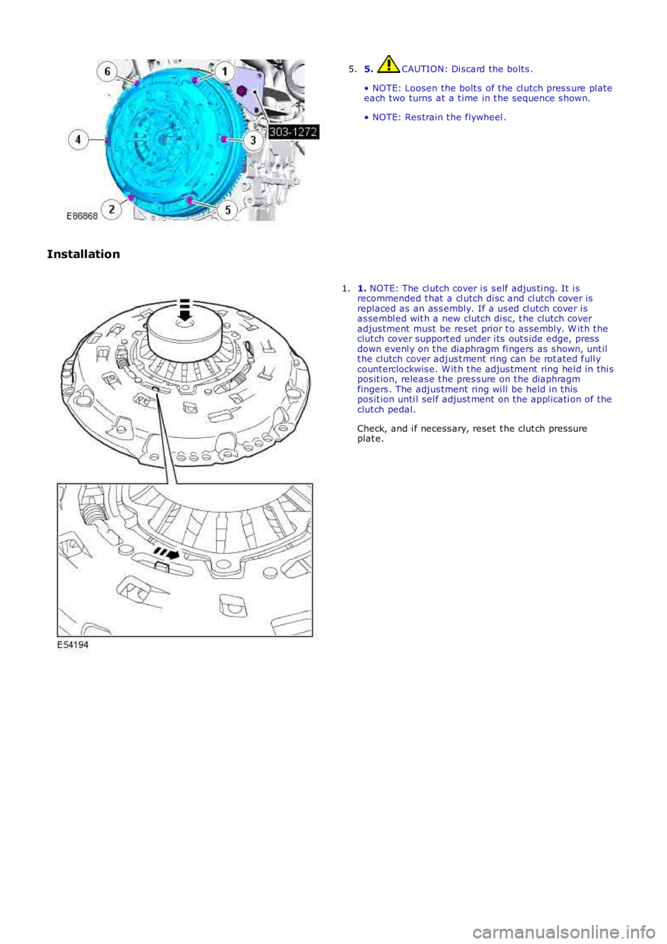
5. CAUTION: Di scard the bolt s .
• NOTE: Loosen the bolt s of t he cl utch pres s ure pl ateeach two turns at a t ime in t he s equence s hown.
• NOTE: Res train t he flywheel .
5.
Installation
1. NOTE: The cl utch cover i s s elf adjus ti ng. It i srecommended t hat a cl utch di sc and cl ut ch cover isrepl aced as an as s embly. If a us ed cl utch cover i sas sembl ed wit h a new clutch di sc, t he clutch coveradjus tment must be res et prior t o as sembl y. W it h t heclut ch cover support ed under i ts out s ide edge, pressdown evenl y on t he diaphragm fi ngers as s hown, unt ilt he clutch cover adjus t ment ri ng can be rot ated full ycount erclockwis e. W it h t he adjus tment ring hel d in thi spos it ion, releas e t he pres s ure on t he diaphragmfingers . The adjus tment ring wi ll be held in t hispos it ion unti l sel f adjust ment on t he appl icati on of theclut ch pedal.
Check, and i f necess ary, reset t he clut ch press ureplat e.
1.
Page 1612 of 3229
Publi s hed: 11-May-2011
Speed Control - I6 3.2L Petrol - Speed Control
Des cript ion and Operat ion
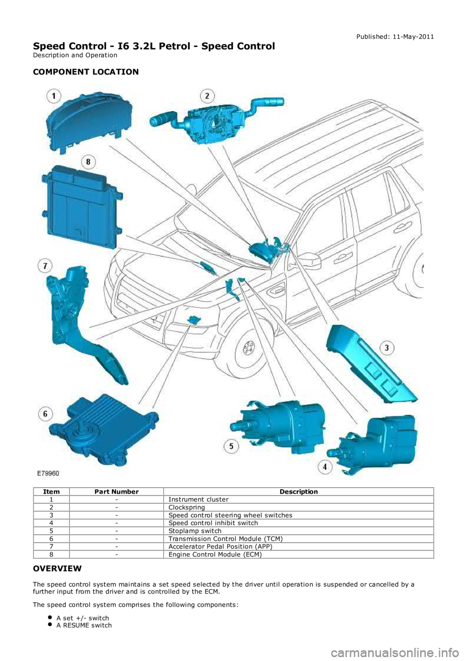
COMPONENT LOCATION
ItemPart NumberDescription1-Ins t rument clus ter
2-Clockspring
3-Speed cont rol s teeri ng wheel s wi tches4-Speed cont rol inhibi t swi tch
5-Stoplamp s wit ch
6-Trans mis s ion Cont rol Modul e (TCM)7-Accelerator Pedal Pos it ion (APP)
8-Engi ne Control Module (ECM)
OVERVIEW
The s peed control sys t em mai nt ains a set s peed s elect ed by t he dri ver unt il operati on is sus pended or cancel led by afurther input from the driver and is controlled by the ECM.
The s peed control sys t em compri ses t he followi ng components :
A s et +/- s wit chA RESUME s wi tch
Page 1613 of 3229
A CANCEL s wit ch.
The s ys t em al so uses t he fol lowi ng:
The ECMThe s toplamp s wit ch.The APP s ens or
The ECM controls t he s et speed by modi fying engine speed/t orque and reques ti ng gear changes from t he transmis si on(aut omati c variant s only).
The s peed control sys t em als o us es i nput s from t he brake pedal swit ch, t he APP s ens or, t he ECM and t he ABS controlmodule.
The s peed control is operat ed by t he dri ver us ing only the s t eering wheel s wit ches . W hen s peed is act ive, the ECMregulat es the PW M s i gnal s to the fuel injectors t o adjus t the fuel supply as required to maintai n t he s et s peed.
Duri ng s peed control operat ion, t he ECM control s vehicle s peed by adjus ti ng fuel inject ion durat ion and ti ming. W hen t heaccelerator pedal i s pres s ed wit h s peed cont rol act ive, t he ECM output s a calculated throt tl e angle s i gnal in place of theact ual throt t le angle si gnal s produced by the APP s ens or. The cal cul ated t hrot tl e angle i s deri ved from fuel demand.
CONTROL SWITCHES
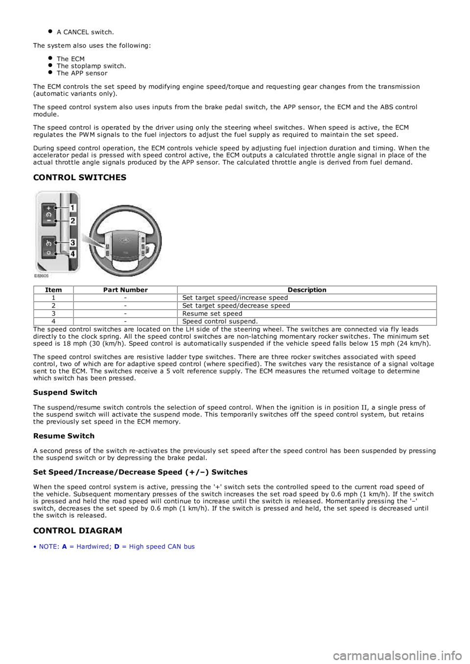
ItemPart NumberDescription1-Set target s peed/increas e s peed
2-Set target s peed/decreas e s peed
3-Resume set s peed4-Speed control sus pend.
The s peed control swit ches are located on t he LH s i de of the s t eering wheel. The s witches are connect ed via fly leadsdirect ly t o t he clock s pring. All t he s peed cont rol s wit ches are non-lat chi ng momentary rocker swit ches . The mini mum s ets peed is 18 mph (30 (km/h). Speed cont rol is aut omati cal ly s us pended i f the vehicle speed falls bel ow 15 mph (24 km/h).
The s peed control swit ches are res is t ive l adder type s wi tches. There are t hree rocker s wit ches as s oci at ed wi th speedcont rol , two of whi ch are for adapt ive s peed cont rol (where s peci fi ed). The s wit ches vary the resi s tance of a s ignal vol tages ent t o t he ECM. The s wit ches recei ve a 5 volt reference s upply. The ECM meas ures t he ret urned volt age to det ermi newhich s wi tch has been pres s ed.
Suspend Switch
The s uspend/resume swit ch controls t he s electi on of speed control. W hen t he i gni ti on is i n pos it ion II, a si ngle pres s oft he sus pend s wit ch wil l act ivate the s us pend mode. This temporaril y s wit ches off the s peed cont rol s yst em, but ret ai nst he previousl y s et s peed i n t he ECM memory.
Resume Switch
A s econd pres s of the s wi tch re-acti vat es the previousl y s et speed after t he s peed control has been s us pended by pres s ingt he sus pend s wit ch or by depres s ing the brake pedal.
Set Speed/Increase/Decrease Speed (+/–) Switches
W hen t he s peed cont rol s ys t em i s act ive, pres s ing t he '+' s wi tch s ets the controlled speed t o t he current road speed oft he vehi cl e. Subs equent moment ary pres s es of the s wi tch i ncreas es t he s et road s peed by 0.6 mph (1 km/h). If t he s wit chis pres sed and hel d the road s peed wil l conti nue to increas e unti l the s wi tch i s releas ed. Moment ari ly press i ng the '–'s wit ch, decreas es the s et s peed by 0.6 mph (1 km/h). If t he s wit ch is press ed and held, t he s et speed i s decreas ed unt ilt he swit ch is released.
CONTROL DIAGRAM
• NOTE: A = Hardwi red; D = Hi gh s peed CAN bus
Page 1623 of 3229
Publi s hed: 11-May-2011
Speed Control - TD4 2.2L Diesel - Speed Control2.2L Diesel
Des cript ion and Operat ion
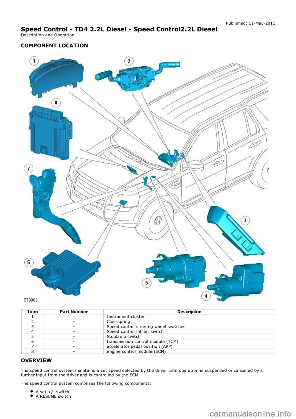
COMPONENT LOCATION
ItemPart NumberDescription1-Ins t rument clus ter
2-Clockspring
3-Speed cont rol s teeri ng wheel s wi tches4-Speed cont rol inhibi t swi tch
5-Stoplamp s wit ch
6-t ransmis s ion control modul e (TCM)7-accelerator pedal pos it ion (APP)
8-engi ne cont rol module (ECM)
OVERVIEW
The s peed control sys t em mai nt ains a set s peed s elect ed by t he dri ver unt il operati on is sus pended or cancel led by afurther input from the driver and is controlled by the ECM.
The s peed control sys t em compri ses t he followi ng components :
A s et +/- s wit chA RESUME s wi tch
Page 1653 of 3229
motor. A Hal l eff ect sens or l ocat ed withi n the st epper motor inf orms the ATC module that move me nt of the ste ppe r motor ist aking pl ace.
Air Temperature Control - Single Zone Manual System
Cabin tempe rature s election is made by turning the LH rota ry controller to t he required pos ition. Turning the controller counterclockwise wil l lower the tempera ture of t he air e xiting the heate r as sembly; turning the control ler clockwise wi ll rai se t het emperat ure of t he a ir exiting the he ate r as sembly.
Maxi mum he ating and cooling is represe nted on the control panel by a red a nd blue dot res pect ivel y. W hen eit her maximumheat ing or cooling is sele cte d, the 'comf ort' algorithm in the ATC modul e wi ll adopt a suitable s trat egy for air s ource, a irdistributi on a nd blower s pee d to ma inta in maximum hea ting or cool ing within t he cabin.
The ATC module adjusts the temperature of the air exit ing t he heat er a ssembly by moving the pos ition of the tempera tureblend door. The tempera ture ble nd door dire cts a proportion of cool ed a ir from t he evaporat or t hrough the heat er core toproduce the required temperature output. The ATC module a djusts t he posi tion of t he t empera ture blend door by provi dingLIN bus mes sage s to the ble nd door ste ppe r motor. A Hall e ffect se nsor located wit hin the stepper motor i nforms t he ATCmodule t hat moveme nt of the st epper motor is taking place .
Air Temperature Control - Dual Zone Automatic System
Dual zone systems f eature 2 rot ary heat ing cont rolle rs, which a llow indi vidual climate control for the LH and RH sides of thecabin. Te mpe rature s election can be ma de by turning the controller to t he requi red tempera ture ma rked on the control panel.Turni ng e ithe r controller pas t the 16°C (61°F) mark will initi ate the maximum cooling s trate gy; turning either controlle r pa stt he 28°C (82°F) mark wi ll initiat e the maximum hea ting stra tegy.
• NO TE: Maximum cooling or hea ting can only be achieved i f both rotary control lers are set to t he s ame position.
The ATC module is a ble to maint ain constant te mpe ratures in both side s of the cabin by monit oring the fee dba ck f rom thecabin temperature se nsor. Unles s any manual overri des have be en s ele cted, the ATC module will a utomati cally control thei ntake ai r source , air dis tribution int o the ca bin and blower spee d to ma inta in t he requi red tempera ture s.
Dual zone systems f eature 2 temperature bl end doors, a llowing individual t emperat ure output for t he LH a nd RH si des of t hecabin.
• NO TE: The drivers side temperature se tting ha s priorit y over t he pass engers s ide tempera ture se tting.
The t empera ture ble nd doors are mounte d on the LH side of the hea ter ass embly a nd direct a proportion of cooled air fromt he e vaporat or through t he heat er core t o provide the re quired t empera ture out puts . The ATC module controls the posi tion oft he t emperat ure blend doors by providing LIN bus mess ages to the blend door stepper mot ors. Hal l eff ect sens ors loca tedwithi n the st epper motors inform the ATC modul e that move ment of the ste ppe r motors is taki ng place .
Blower Motor Control - Single Zone Manual System
Blower motor spe ed is se t by turning the RH rot ary cont rolle r to the require d position. The RH rotary controller allows t hes election of 14 blowe r motor spe eds . Turning the controller fully counte r clockwise will turn the blower mot or off.
O peration of the blower mot or is control led by t he ATC module via t he blower motor control module . The ATC module provi desa PW M s igna l to the blower mot or control modul e ba sed on the sele cted blower spe ed. The blower mot or control modulei nterpret s the PW M s igna l as a blower motor spe ed and controls the vol tage to the blower mot or a ccordingly.
Blower Motor Control - Dual Zone Automatic System
Blower motor spe ed is controlled automa tica lly by the ATC module unle ss a ma nual override ha s be en requeste d. Manualoverrides to blower motor speed can be made by turning the centra l rot ary cont rolle r to the require d position. The rota rycontrolle r all ows the manual sele ction of 7 blower motor spe eds . Turning the controller fully counte r clockwise will turn theblower motor off . W hen a manua l override has been ma de, the 'AUTO' LED loca ted in the ce nte r of the rota ry controlle r wil le xtinguis h.
• NO TE: The central rota ry controller contains 2 LED's. The t op (round) LED will illumina te when the blower motor i s undera utomati c control. The bottom (recta ngular) LED wil l illuminated when a ir distri bution i nto the cabi n is under a utomati ccontrol (s ee below).
The blower motor ca n be ret urne d to aut oma tic cont rol by press ing the 'AUTO' s witch locate d in the center of t he rotarycontrolle r. Under aut oma tic cont rol, the ATC module varies t he s pee d of the blower motor i n line with i ts 'comf ort' algorithmt o maint ain t he required cabin te mperat ure. The ATC modul e wi ll al so vary the blower motor speed to compens ate for the rame ffect on inta ke air produced by forward moveme nt of the ve hicl e.
O peration of the blower mot or is control led by t he ATC module via t he blower motor control module . The ATC module provi desa PW M s igna l to the blower mot or control modul e ba sed on the required blower spe ed. The blower mot or control modulei nterpret s the PW M s igna l as a blower motor spe ed and controls the vol tage to the blower mot or a ccordingly.
Air Distribution Control - Single Zone Manual System
Air distri buti on into t he cabi n ca n be adj uste d by turning the ce ntra l rot ary cont rolle r to the require d positi on. The ATC modulea djus ts t he posit ion of t he a ir di stribution door to the re qui red posi tion by providing LIN bus messa ges to the air distribut iondoor stepper motor. A Ha ll e ffect se nsor loca ted wit hin the stepper mot or informs t he ATC module that movement of t hes tepper motor is taking place.
Air Distribution Control - Dual Zone Automatic System
Air distri buti on into t he cabi n is cont rolle d a utomati cally by the ATC module unless any ma nual ove rrides have bee nreque ste d. Manual overri des can be made by pre ssing the a ppropria te a ir di stribution mome nta ry s witch on the control panel.If a manual override has bee n re que sted, the 'AUTO ' LED locate d in the center of the blowe r motor rota ry controlle r wi lle xtinguis h.
• NO TE: The central rota ry controller contains 2 LED's. The t op (round) LED will illumina te when the blower motor i s undera utomati c control (se e a bove ). The bott om (rect angular) LED wi ll ill uminate d when air distribut ion into the cabin is under
Page 1795 of 3229
The current vehicle operat ing mode, s hown in parenthes is above, i s dis played in the odomet er for 5 s econds when t hevehi cl e first ent ers power mode 6.
• NOTE: 'Nor' is only di s pl ayed in t he Odometer when t he vehicle operat ing mode is changed t o normal from any of theother vehi cle operat ing modes . Under al l ot her condit ions , 'Nor' is not di spl ayed.
The vehi cl e operat ing mode can be changed us i ng the Land Rover approved di agnos ti c sys t em.
Gear Position
The gear pos it ion i ndicat or s hows the current aut omati c t ransmis s ion s elector l ever posi ti on. During normal operat ion thedis play wi ll s how P (park), R (revers e), N (neutral) and D (drive). W hen the t rans mis s ion is operat ed in 'CommandShi ft ™'mode, the odomet er di spl ays the current ly sel ect ed manual gear; 1, 2, 3, 4, 5 or 6.
In the event of eit her a CAN bus fai lure, or if t he TCM det ect s a t rans mi ss i on overheat s it uati on, t he odometer wi ll dis playt he let ter 'E' in the s ame area of t he dis play as t he 'CommandShift™' s elected gear informat ion.
Supplemental Restrain System Warning Indicator
If the i nst rument clus ter det ect s the Supplement al Res t raint Sys tem (SRS) warni ng indicator has fai led, t he mes sage 'SrS'wil l be dis played in the odomet er and a DTC s tored. The DTC can be ret rieved from the ins trument cl us t er us i ng the LandRover approved diagnost ic sys tem.
Service Interval Indicator
The Service Interval Indi cat or (SII) i nforms t he driver when t he next vehicle servi ce is due. The ins t rument clus ter monit orst he dis tance t he vehi cl e has travel ed and t he ti me el aps ed s ince t he las t s ervice.
If vehicle dis tance is the t rigger for the SII, 'SERVICE' will be di s pl ayed in t he odometer accompanied by a dis tancequal ifier (ei ther 'MILES' or 'KM' dependi ng on t he ins trument cl ust er s pecificati on). A di st ance counter wi ll als o be di s pl ayedin the t op Ri ght Hand (RH) corner of t he odometer. If t he point at which a servi ce is requi red is pas sed, t he count er wi lldis play a negat ive value. W hen acti vat ed, t he SII is di spl ayed for 5 s econds when t he vehi cl e enters power mode 6.
If ti me i s the trigger for the SII, 'SERVICE' wil l be di s pl ayed in t he odometer accompanied by a clock symbol . A count er willals o be di spl ayed i n t he t op RH corner of the odomet er. If t he point at which a s ervice is required is pas s ed, t he count erwil l dis play a negati ve val ue. Agai n, when act ivated t he SII is dis played for 5 s econds when t he vehi cl e enters power mode6.
If bot h t he dis tance and t ime triggers are acti vat ed, t he SII wil l di s pl ay the di s tance informat ion for 5 s econds, foll owedby t he ti me i nformati on for 5 s econds .
W hen a service has been carri ed out , t he SII wi ll need t o be re-s et. This can be done us ing t he Land Rover approveddiagnost ic s ys tem or foll owing a manual re-s et procedure. The manual re-s et mode is ent ered by carrying out the foll owingrout ine:
Pres s and hold the t ri p res et butt on wi th the vehicle st ati onary and in a power mode les s t han 6.W hi le holdi ng the trip res et but ton, enter t he vehi cl e int o power mode 6.Releas e the trip res et but ton wit hi n 10 s econds of entering power mode 6.
If the manual re-set mode has been s ucces s full y entered 'dISt ' or 'DATE' wi ll be di spl ayed i n t he odomet er, dependi ng onwhich t ri gger has been acti vat ed.
To clear the 'dISt ' trigger pres s, and hold the t rip reset but ton for more than 5 s econds wit hi n 10 s econds of entering t hemanual re-s et mode. If s ucces s ful, 'RESET' wil l be dis played in the odometer for 5 seconds. If t he dat e t ri gger has notbeen act ivated 'END' wil l t hen be dis played i n t he odomet er.
• NOTE: The dis t ance t ri gger wi ll not res et if t he dis t ance t he vehi cle has t raveled i s les s t han 20% of t he next s ervi ceint erval val ue.
If the dat e trigger has been act ivated, 'DATE' wil l be dis played in t he odometer. To clear the t ri gger, pres s and hold t het rip res et but t on for more t han 5 s econds wit hin 10 s econds of 'DATE' being di s pl ayed. If succes s ful , 'RESET' wi ll bedis played wit hin the odomet er for 5 s econds fol lowed by 'END'. The odomet er wil l now exit re-s et mode.
AMBIENT AIR TEMPERATURE
The ins t rument clus ter can dis play t he ambient air t emperature readi ng in ei ther degrees Cels ius or Fahrenhei t. Theambient air t emperat ure s ignal ori gi nat es i n the ambient air t emperature s ens or. The s ens or i s a Negati ve TemperatureCoefficient (NTC) t hermi st or, and i s mounted i n t he LH door mirror. A t emperature value i s cal cul ated by t he ECM andbroadcas t over the hi gh speed CAN bus to t he i ns t rument clus ter.
If the t emperat ure value fall s bel ow 4ºC (39ºF) t he mes sage center wi ll flas h the low ambi ent ai r temperat ure icon 5t imes . Thi s i s accompanied by a chime from the i nst rument clus t er s ounder. The low ambient air t emperature icon wi ll berepeated if t he ambient air t emperature ri s es above 6ºC (43ºF) t hen drops below 4ºC (39ºF) again or a new ignit ion cycleis st art ed.