2006 LAND ROVER FRELANDER 2 fuse
[x] Cancel search: fusePage 647 of 3229
SymptomAction
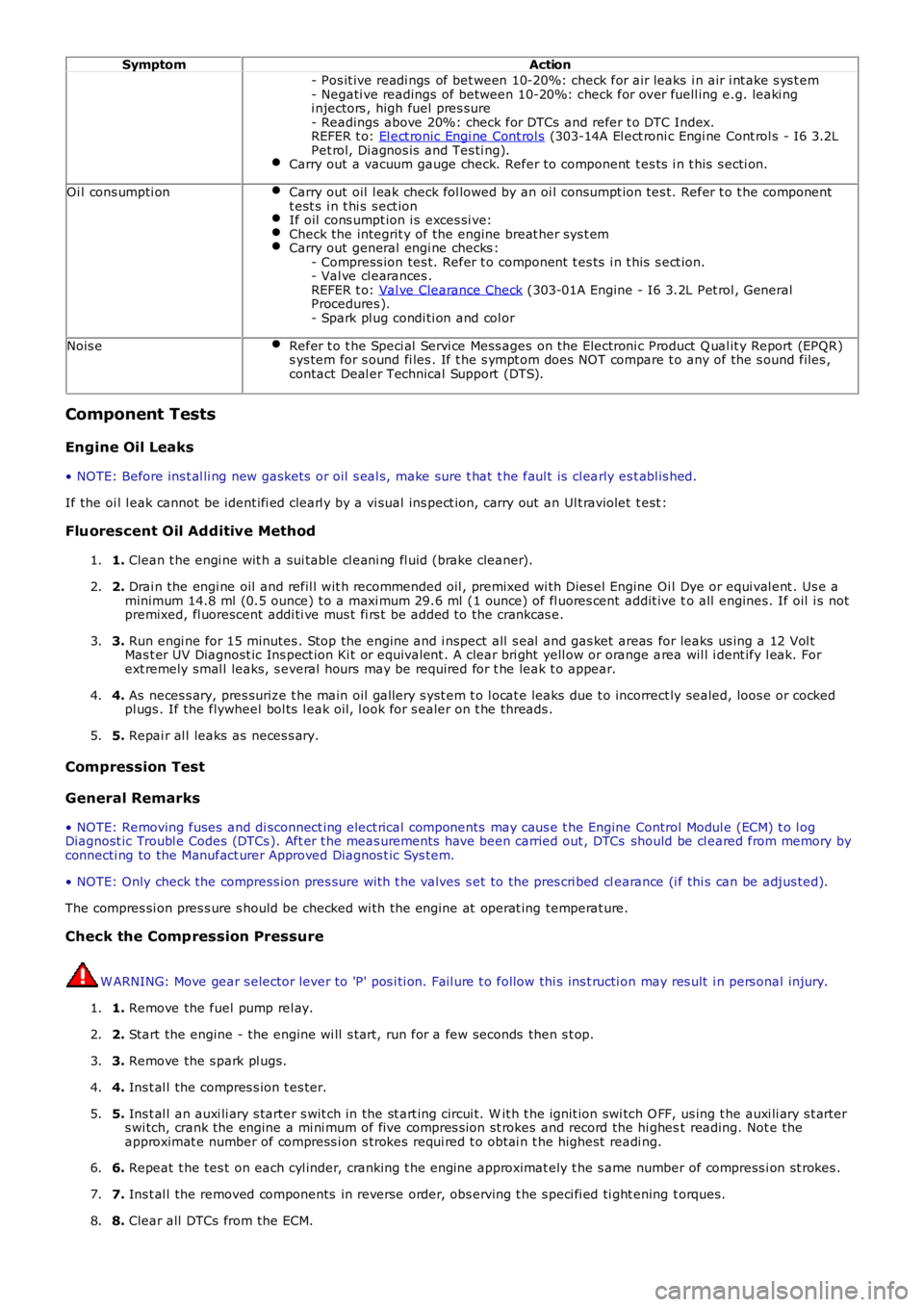
- Pos it ive readi ngs of bet ween 10-20%: check for air leaks i n air i nt ake s ys t em- Negati ve readings of between 10-20%: check for over fuell ing e.g. leaki ngi njectors , high fuel pres sure- Readings above 20%: check for DTCs and refer t o DTC Index.REFER t o: El ect ronic Engi ne Cont rol s (303-14A El ect roni c Engi ne Cont rol s - I6 3.2LPet rol, Di agnos is and Tes ti ng).Carry out a vacuum gauge check. Refer to component t es ts i n t his s ecti on.
Oi l cons umpti onCarry out oil l eak check fol lowed by an oi l cons umpt ion tes t. Refer t o t he componentt est s i n t hi s s ect ionIf oil cons umpt ion i s exces si ve:Check the integrit y of the engine breat her sys t emCarry out general engi ne checks :- Compress ion tes t. Refer t o component t es ts i n t his s ect ion.- Val ve cl earances .REFER t o: Val ve Clearance Check (303-01A Engine - I6 3.2L Pet rol , GeneralProcedures ).- Spark pl ug condi ti on and col or
Nois eRefer t o t he Speci al Servi ce Mess ages on t he Electroni c Product Q ual it y Report (EPQR)s ys tem for s ound fi les . If t he s ympt om does NOT compare t o any of the s ound files ,contact Deal er Technical Support (DTS).
Component Tests
Engine Oil Leaks
• NOTE: Before ins t al li ng new gasket s or oil s eal s, make sure t hat t he faul t is cl early es t abl is hed.
If the oi l l eak cannot be ident ifi ed clearl y by a vi sual ins pect ion, carry out an Ult raviolet t est :
Fluorescent Oil Additive Method
1. Clean t he engi ne wit h a sui table cl eani ng fl uid (brake cleaner).1.
2. Drai n the engi ne oil and refil l wit h recommended oil , premixed wi th Dies el Engine Oil Dye or equi val ent . Us e aminimum 14.8 ml (0.5 ounce) t o a maxi mum 29.6 ml (1 ounce) of fl uores cent addit ive to all engines. If oil i s notpremixed, fl uorescent addi ti ve mus t fi rs t be added to the crankcas e.
2.
3. Run engi ne for 15 minutes . Stop the engine and i nspect all s eal and gas ket areas for leaks us ing a 12 Vol tMas t er UV Diagnost ic Ins pect ion Ki t or equivalent . A clear bri ght yell ow or orange area wil l i dent ify l eak. Forext remely smal l leaks, s everal hours may be required for t he leak t o appear.
3.
4. As neces s ary, pres surize t he main oil gallery s yst em t o l ocat e leaks due t o incorrect ly sealed, loos e or cockedpl ugs . If the flywheel bol ts l eak oil, l ook for s ealer on t he threads .4.
5. Repai r al l leaks as neces s ary.5.
Compression Test
General Remarks
• NOTE: Removing fuses and di sconnect ing elect rical components may caus e t he Engine Control Modul e (ECM) t o l ogDiagnost ic Troubl e Codes (DTCs ). Aft er t he meas urements have been carried out , DTCs should be cl eared from memory byconnecti ng to the Manufact urer Approved Diagnos t ic Sys tem.
• NOTE: Only check the compress ion pres sure wit h t he valves s et to the pres cri bed clearance (i f thi s can be adjus ted).
The compres si on pres s ure s hould be checked wi th the engine at operat ing temperat ure.
Check the Comp ression Pressure
W ARNING: Move gear s elector lever to 'P' pos i ti on. Fail ure t o follow thi s ins t ructi on may res ult i n pers onal injury.
1. Remove the fuel pump rel ay.1.
2. Start the engine - the engine wi ll s t art, run for a few seconds then s t op.2.
3. Remove the s park pl ugs.3.
4. Ins t al l the compres s ion t es ter.4.
5. Ins t al l an auxi li ary s tarter s wit ch in the st art ing circui t. W it h t he ignit ion swi tch O FF, us ing t he auxi li ary s t arters wi tch, crank the engine a mi ni mum of five compres s ion st rokes and record the hi ghest reading. Not e theapproximat e number of compress i on s trokes requi red t o obt ai n t he highest readi ng.
5.
6. Repeat t he tes t on each cyl inder, cranking t he engine approximat ely t he s ame number of compress i on st rokes .6.
7. Ins t al l the removed components in reverse order, obs erving t he s peci fi ed ti ght ening t orques.7.
8. Clear all DTCs from the ECM.8.
Page 913 of 3229
Publi s hed: 11-May-2011
Engine Cooling - I6 3.2L Petrol - Engine Cooling
Diagnosi s and Tes ti ng
Principles of Operation
For a detail ed descripti on of the cooli ng s ys t em, refer t o t he rel evant Des cript ion and Operat ion secti on in the workshopmanual.REFER to: Engine Cooli ng (303-03A Engi ne Cool ing - I6 3.2L Pet rol , Descri pti on and Operat ion).
Inspection and Verification
CAUTION: Di agnos is by s ubs ti tut ion from a donor vehicle is NO T acceptabl e. Subs ti tut ion of cont rol modules doesnot guarant ee confirmat ion of a faul t, and may als o caus e addit ional fault s i n t he vehi cl e being t est ed and/or t he donorvehi cl e.
1. Verify t he cus t omer concern.1.
2. Vis ually ins pect for obvious s igns of mechani cal or electrical damage.2.
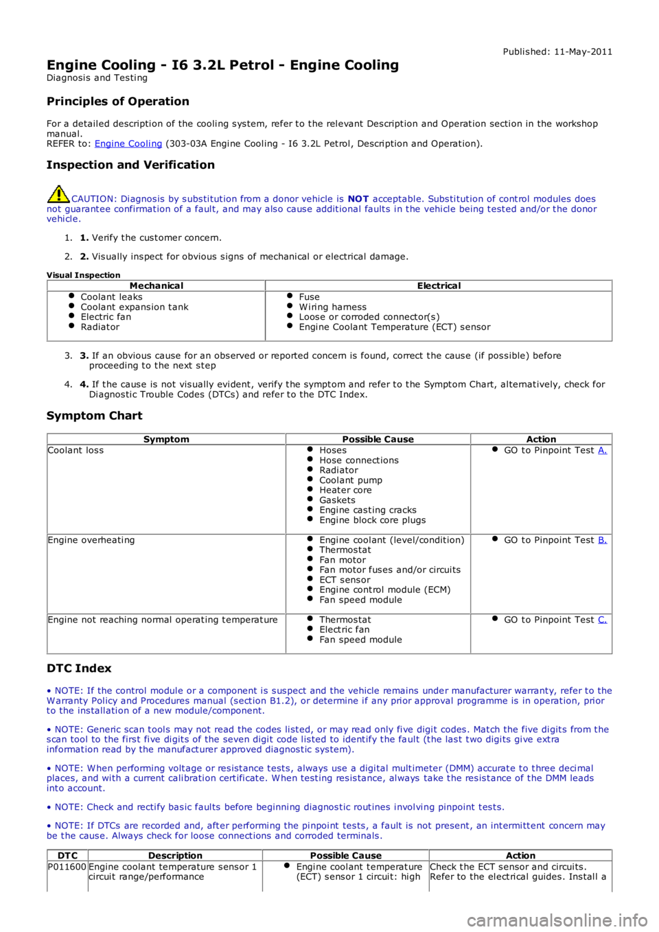
Visual InspectionMechanicalElectrical
Coolant leaksCoolant expans ion t ankElectric fanRadiat or
FuseW i ri ng harnessLoos e or corroded connect or(s )Engi ne Coolant Temperature (ECT) s ensor
3. If an obvious cause for an obs erved or report ed concern is found, correct t he caus e (if pos s ible) beforeproceeding t o t he next s t ep3.
4. If t he caus e is not vis ually evi dent , verify t he sympt om and refer t o t he Sympt om Chart, al ternat ively, check forDi agnos ti c Trouble Codes (DTCs) and refer t o t he DTC Index.4.
Symptom Chart
SymptomPossible CauseActionCoolant los sHosesHose connect ionsRadi atorCool ant pumpHeat er coreGasketsEngi ne cas t ing cracksEngi ne block core plugs
GO t o Pinpoint Test A.
Engine overheati ngEngi ne cool ant (level/condit ion)Thermos tatFan motorFan motor fus es and/or circui tsECT s ens orEngi ne cont rol module (ECM)Fan speed module
GO t o Pinpoint Test B.
Engine not reaching normal operat ing t emperat ureThermos tatElect ric fanFan speed module
GO t o Pinpoint Test C.
DTC Index
• NOTE: If the control modul e or a component i s s us pect and the vehicle remains under manufacturer warrant y, refer t o theW arranty Pol icy and Procedures manual (s ect ion B1.2), or determine i f any pri or approval programme is in operat ion, pri ort o the ins tall ati on of a new module/component.
• NOTE: Generic scan t ool s may not read the codes li st ed, or may read only fi ve digit codes . Mat ch the five di git s from t hes can tool to the firs t fi ve di git s of the seven digi t code l is ted to ident ify t he faul t (t he las t t wo digi ts gi ve ext rainformat ion read by the manufact urer approved diagnos t ic s ys tem).
• NOTE: W hen performing volt age or res is t ance t est s , always use a digi tal mult imeter (DMM) accurat e t o t hree deci malplaces, and wi th a current cali brati on cert ifi cat e. W hen t est ing res is tance, al ways take t he res is t ance of t he DMM leadsint o account.
• NOTE: Check and recti fy bas ic faul ts before beginni ng diagnos t ic rout ines i nvol vi ng pinpoint t es t s.
• NOTE: If DTCs are recorded and, aft er performi ng the pi npoi nt tes ts , a fault is not present , an int ermi tt ent concern maybe t he caus e. Always check for loose connect ions and corroded terminals .
DT CDescriptionPossible CauseAction
P011600Engine coolant temperature s ens or 1circui t range/performanceEngi ne cool ant t emperat ure(ECT) s ens or 1 circui t: hi ghCheck t he ECT s ensor and circui ts .Refer to the el ect ri cal guides . Ins tal l a
Page 947 of 3229
Publi s hed: 11-May-2011
Engine Cooling - TD4 2.2L Diesel - Engine Cooling
Diagnosi s and Tes ti ng
Principles of Operation
For a detail ed descripti on of the cooli ng s ys t em, refer t o t he rel evant Des cript ion and Operat ion secti on in the workshop
manual.
REFER to: Engine Cooli ng (303-03B Engi ne Cool ing - TD4 2.2L Dies el, Des cript ion and Operat ion).
Inspection and Verification CAUTION: Di agnos is by s ubs ti tut ion from a donor vehicle is
NO T acceptabl e. Subs ti tut ion of cont rol modules does
not guarant ee confirmat ion of a faul t, and may als o caus e addit ional fault s i n t he v ehi cl e being t est ed and/or t he donor
vehi cl e.
1. Verify t he cus t omer concern.
1.
2. Vis ually ins pect for obvious s igns of mechani cal or electrical damage.
2.
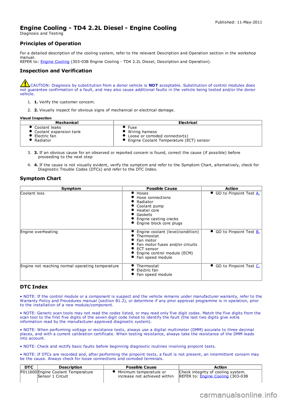
Visual Inspection Mechanical Electrical
Coolant leaks Coolant expans ion t ank
Electric fan
Radiat or Fuse
W i ri ng harness
Loos e or corroded connect or(s )
Engi ne Coolant Temperature (ECT) s ensor
3.
If an obvious cause for an obs erved or report ed concern is found, correct t he caus e (if pos s ible) before
proceeding t o t he next s t ep
3.
4. If t he caus e is not vis ually evi dent , verify t he sympt om and refer t o t he Sympt om Ch art, al ternat ively, check for
Di agnos ti c Trouble Codes (DTCs) and refer t o t he DTC Index.
4.
Symptom Chart Symptom Possible CauseAction
Coolant los s Hoses Hose connect ions
Radi ator
Cool ant pump
Heat er core
Gaskets
Engi ne cas t ing cracks
Engi ne block core plugs GO t o Pinpoint Test
A.Engine overheati ng
Engi ne cool ant (level/condit ion) Thermos tat
Fan motor
Fan motor fus es and/or circui ts
ECT s ens or
Engi ne cont rol module (ECM)
Fan speed module GO t o Pinpoint Test
B.Engine not reaching normal operat ing t emperat ure
Thermos tat Elect ric fan
Fan speed module GO t o Pinpoint Test
C.DTC Index
• NOTE: If the control modul e or a component i s s us pect and the vehicle remains unde r manufacturer warrant y, refer t o the
W arranty Pol icy and Procedures manual (s ect ion B1.2), or determine i f any pri or appr oval programme is in operat ion, pri or
t o the ins tall ati on of a new module/component.
• NOTE: Generic scan t ool s may not read the codes li st ed, or may read only fi ve digi t codes . Mat ch the five di git s from t he
s can tool to the firs t fi ve di git s of the seven digi t code l is ted to ident ify t he fa ul t (t he las t t wo digi ts gi ve ext ra
informat ion read by the manufact urer approved diagnos t ic s ys tem).
• NOTE: W hen performing volt age or res is t ance t est s , always use a digi tal mult imeter (DMM) accurat e t o t hree deci mal
places, and wi th a current cali brati on cert ifi cat e. W hen t est ing res is tance, al ways take t he res is t ance of t he DMM leads
int o account.
• NOTE: Check and recti fy bas ic faul ts before beginni ng diagnos t ic rout ines i nvol vi n g pinpoint t es t s.
• NOTE: If DTCs are recorded and, aft er performi ng the pi npoi nt tes ts , a fault is no t present , an int ermi tt ent concern may
be t he caus e. Always check for loose connect ions and corroded terminals .
DT C Description Possible Cause Action
P011600 Engine Coolant Temperat ure
Sensor 1 Circuit Mini mum temperat ure or
increas e not achi eved wi thi n Check int egrit y of cool ing s ys tem.
REFER t o: Engi ne Cool ing (303-03B
Page 978 of 3229
Publi s hed: 11-May-2011
Fuel Charging and Controls - I6 3.2L Petrol - Fuel Charging and Controls
Diagnosi s and Tes ti ng
Principles of Operation
For a detail ed descripti on of the fuel chargi ng and cont rol s, refer t o the relevant Descri pti on and Operat ion s ect ion in t heworks hop manual .REFER to: Fuel Chargi ng and Controls (303-04A Fuel Chargi ng and Cont rol s - I6 3.2L Pet rol, Des cri pt ion and Operati on).
Inspection and Verification
CAUTION: Di agnos is by s ubs ti tut ion from a donor vehicle is NO T acceptabl e. Subs ti tut ion of cont rol modules doesnot guarant ee confirmat ion of a faul t, and may als o caus e addit ional fault s i n t he vehi cl e being t est ed and/or t he donorvehi cl e.
• NOTE: For di agnos t ic purpos es the cyli nders are divided i nt o t wo banks: Bank 1 - Cyl inder numbers 1, 2 and 3. Bank 2 -Cylinders 4, 5 and 6
1. Verify t he cus t omer concern.1.
2. Vis ually ins pect for obvious s igns of mechani cal or electrical damage.2.
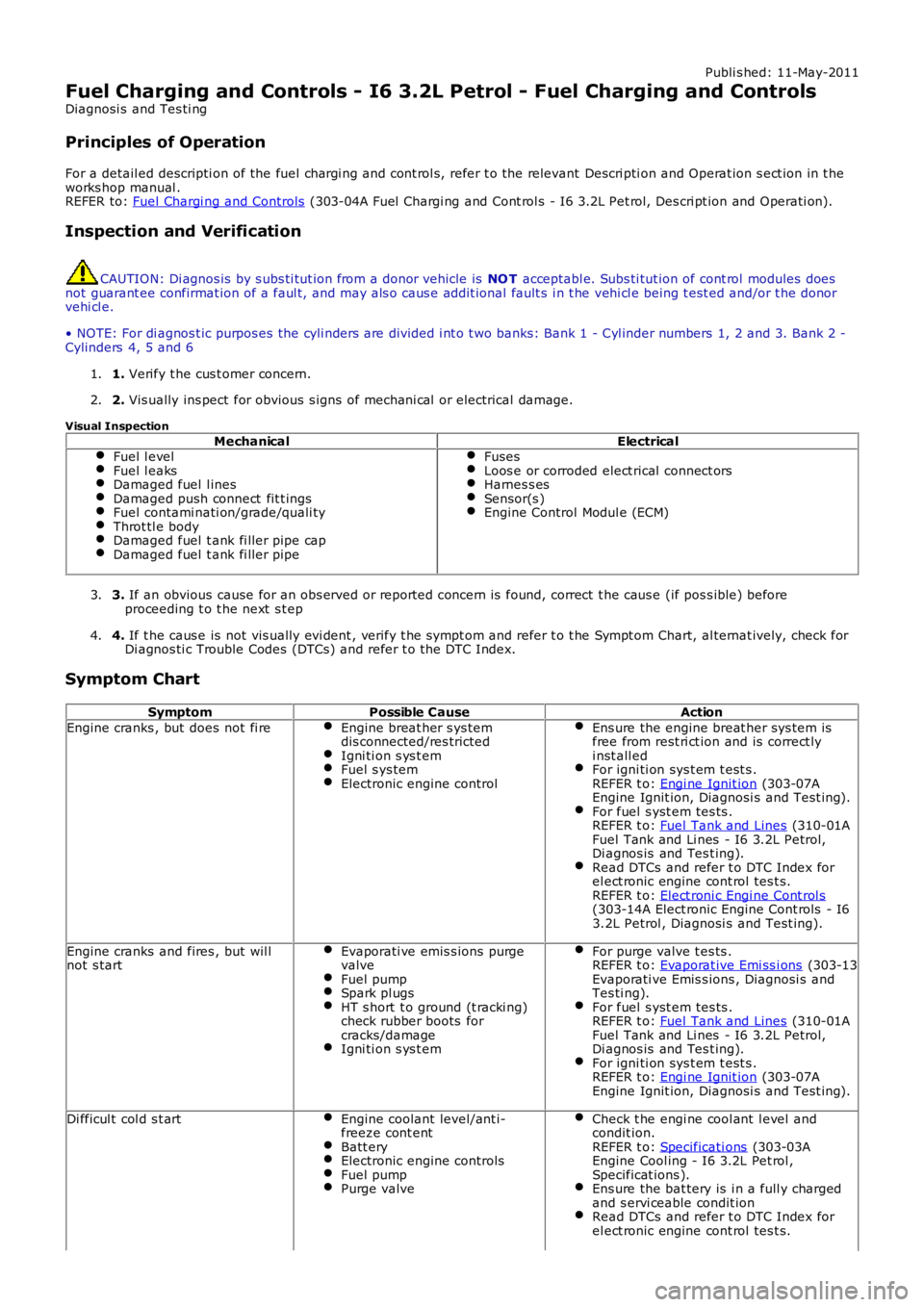
Visual Inspection
MechanicalElectricalFuel l evelFuel l eaksDamaged fuel l inesDamaged push connect fit t ingsFuel contami nati on/grade/quali tyThrot tl e bodyDamaged fuel t ank fi ller pipe capDamaged fuel t ank fi ller pipe
FusesLoos e or corroded elect rical connect orsHarnes s esSensor(s )Engine Control Modul e (ECM)
3. If an obvious cause for an obs erved or report ed concern is found, correct t he caus e (if pos s ible) beforeproceeding t o t he next s t ep3.
4. If t he caus e is not vis ually evi dent , verify t he sympt om and refer t o t he Sympt om Chart, al ternat ively, check forDi agnos ti c Trouble Codes (DTCs) and refer t o t he DTC Index.4.
Symptom Chart
SymptomPossible CauseAction
Engine cranks , but does not fi reEngine breat her s ys temdis connected/res trictedIgni ti on s ys t emFuel s ys temElectronic engine control
Ens ure the engine breat her sys tem isfree from rest ri ct ion and is correct lyi nst all edFor igni ti on sys t em t est s .REFER t o: Engi ne Ignit ion (303-07AEngine Ignit ion, Diagnosi s and Test ing).For fuel s yst em tes ts .REFER t o: Fuel Tank and Lines (310-01AFuel Tank and Li nes - I6 3.2L Petrol,Di agnos is and Tes t ing).Read DTCs and refer t o DTC Index forel ect ronic engine cont rol tes t s.REFER t o: Elect roni c Engi ne Cont rol s(303-14A Elect ronic Engine Cont rols - I63.2L Petrol , Diagnosi s and Test ing).
Engine cranks and fires , but wil lnot s tartEvaporati ve emis s ions purgevalveFuel pumpSpark pl ugsHT s hort t o ground (t racki ng)check rubber boots forcracks/damageIgni ti on s ys t em
For purge valve t es ts .REFER t o: Evaporat ive Emi ss i ons (303-13Evaporati ve Emis s ions , Diagnosi s andTes ti ng).For fuel s yst em tes ts .REFER t o: Fuel Tank and Lines (310-01AFuel Tank and Li nes - I6 3.2L Petrol,Di agnos is and Tes t ing).For igni ti on sys t em t est s .REFER t o: Engi ne Ignit ion (303-07AEngine Ignit ion, Diagnosi s and Test ing).
Di fficul t col d s t artEngine coolant level/ant i-freeze cont entBatt eryElectronic engine controlsFuel pumpPurge valve
Check t he engi ne cool ant l evel andcondit ion.REFER t o: Specificati ons (303-03AEngine Cool ing - I6 3.2L Pet rol ,Specificat ions ).Ens ure the bat tery is i n a full y chargedand s ervi ceable condit ionRead DTCs and refer t o DTC Index forel ect ronic engine cont rol tes t s.
Page 1124 of 3229
Publi s hed: 11-May-2011
Glow Plug System - Glow Plug System
Diagnosi s and Tes ti ng
Principles of Operation
For a detail ed descripti on of the gl ow plug sys tem, refer t o t he rel evant Des cript ion and Operat ion s ecti on in the works hopmanual.REFER to: Gl ow Plug Sys tem (303-07B Glow Pl ug Syst em, Des cript ion and Operat ion).
Inspection and Verification
CAUTION: Di agnos is by s ubs ti tut ion from a donor vehicle is NO T acceptabl e. Subs ti tut ion of cont rol modules doesnot guarant ee confirmat ion of a faul t, and may als o caus e addit ional fault s i n t he vehi cl e being t est ed and/or t he donorvehi cl e.
1. Verify t he cus t omer concern.1.
2. Vis ually ins pect for obvious s igns of damage.2.
Visual InspectionElectrical
Fuse(s )Gl ow plug relayEngine management cont rol rel ayW iri ng harnes sElectrical connect or(s )Gl ow plug(s )Engine control modul e (ECM)
3. If an obvious cause for an obs erved or report ed concern is found, correct t he caus e (if pos s ible) beforeproceeding t o t he next s t ep3.
4. If t he caus e is not vis ually evi dent , verify t he sympt om and refer t o t he Sympt om Chart.4.
DTC Index
• NOTE: If the control modul e or a component i s s us pect and the vehicle remains under manufacturer warrant y, refer t o theW arranty Pol icy and Procedures manual (s ect ion B1.2), or determine i f any pri or approval programme is in operat ion, pri ort o the ins tall ati on of a new module/component.
• NOTE: Generic scan t ool s may not read the codes li st ed, or may read only fi ve digit codes . Mat ch the five di git s from t hes can tool to the firs t fi ve di git s of the seven digi t code l is ted to ident ify t he faul t (t he las t t wo digi ts gi ve addi ti onalinformat ion read by the manufact urer approved diagnos t ic s ys tem).
• NOTE: W hen performing volt age or res is t ance t est s , always use a digi tal mult imeter (DMM) accurat e t o t hree deci malplaces, and wi th an up-t o-date cal ibrat ion cert ificate. W hen tes ti ng res is t ance al ways take t he res is t ance of t he DMMleads i nt o account .
• NOTE: Check and recti fy bas ic faul ts before beginni ng diagnos t ic rout ines i nvol vi ng pinpoint t es t s.
• NOTE: Ins pect connect ors for s igns of water ingres s , and pins for damage and/or corros ion.
• NOTE: If DTCs are recorded and, aft er performi ng the pi npoi nt tes ts , a fault is not present , an int ermi tt ent concern maybe t he caus e. Always check for loose connect ions and corroded terminals .
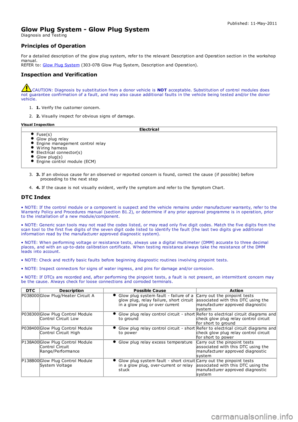
DT CDescriptionPossible CauseAction
P038000Gl ow Plug/Heat er Circuit AGl ow plug s ys tem fault - fail ure of aglow plug, rel ay fail ure, s hort circuiti n a gl ow plug or over current
Carry out t he pinpoint t es t sas s oci ated wi th thi s DTC us ing t hemanufact urer approved diagnos t ics ys tem
P038300Gl ow Plug Cont rol Modul eControl Circuit LowGl ow plug relay control ci rcuit - s hortt o groundRefer to el ect ri cal circui t diagrams andcheck glow pl ug rel ay cont rol ci rcuitfor s hort to ground
P038400Gl ow Plug Cont rol Modul eControl Circuit Hi ghGl ow plug relay control ci rcuit - s hortt o powerRefer to el ect ri cal circui t diagrams andcheck glow pl ug rel ay cont rol ci rcuitfor s hort to powerP138A00Gl ow Plug Cont rol Modul eControl CircuitRange/Performance
Gl ow plug relay exces s t emperat ureCarry out t he pinpoint t es t sas s oci ated wi th thi s DTC us ing t hemanufact urer approved diagnos t ics ys temP138B00Gl ow Plug Cont rol Modul eSys tem Vol tageGl ow plug s ys tem fault - short ci rcuiti n a gl ow plug, over-current or relays t uck
Carry out t he pinpoint t es t sas s oci ated wi th thi s DTC us ing t hemanufact urer approved diagnos t ics ys tem
Page 1202 of 3229
12-Res trai nts Cont rol Module (RCM)
13-Knock sens ors (2 off)
14-Fuel rail t emperature/pres s ure s ens or15-Clockspring
16-Terrain respons e cont rol module
17-Trans mis s ion Cont rol Module (TCM)18-ABS module
19-Diagnos ti c socket
20-CJB
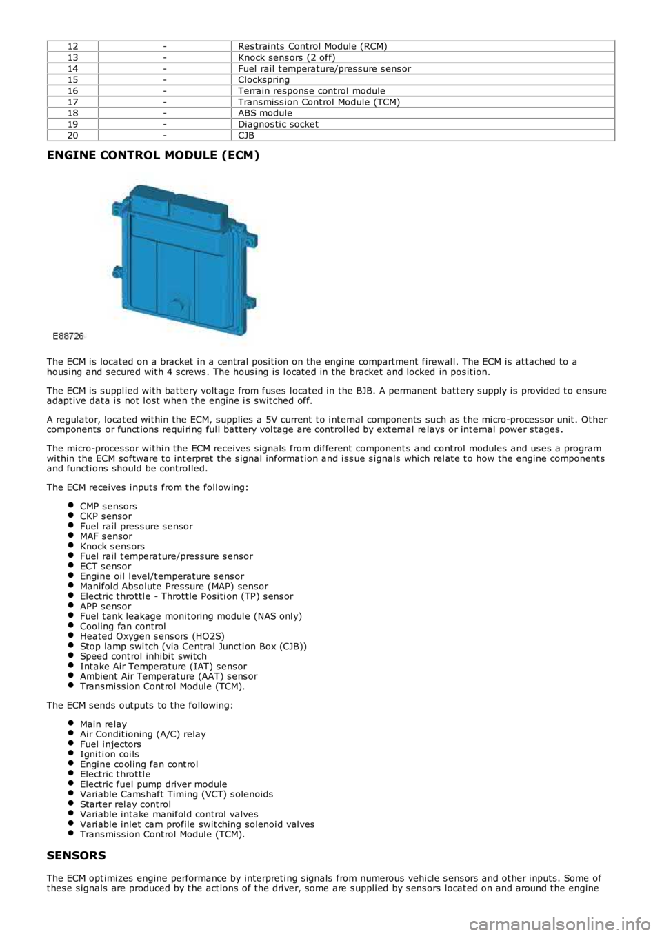
ENGINE CONTROL MODULE (ECM)
The ECM i s located on a bracket i n a central pos i ti on on the engi ne compartment firewal l. The ECM is at tached to ahous i ng and s ecured wit h 4 s crews . The hous i ng is l ocat ed in the bracket and locked in pos it ion.
The ECM i s s uppl ied wi th bat tery volt age from fuses l ocat ed in the BJB. A permanent batt ery s upply i s provided t o ens ureadapt ive dat a is not l ost when the engine i s s wit ched off.
A regul ator, locat ed wi thin the ECM, s upplies a 5V current t o i nt ernal components such as t he mi cro-proces s or unit . Ot hercomponents or funct ions requi ri ng ful l bat tery vol tage are cont rol led by ext ernal relays or int ernal power s t ages .
The mi cro-proces sor wi thi n the ECM receives s ignals from different component s and cont rol modules and us es a programwit hin the ECM software t o int erpret t he s ignal informat ion and i ss ue s ignals whi ch rel at e t o how the engine component sand functi ons should be cont rol led.
The ECM recei ves i nput s from the foll owing:
CMP s ensorsCKP s ensorFuel rail pres s ure s ensorMAF s ensorKnock s ens orsFuel rail t emperature/pres s ure s ensorECT s ens orEngi ne oil l evel/t emperature s ens orManifol d Abs olute Pres sure (MAP) sens orElectric t hrot tl e - Throt tl e Posi ti on (TP) s ens orAPP s ens orFuel t ank leakage monit oring modul e (NAS onl y)Cooling fan controlHeated Oxygen s ens ors (HO2S)Stop lamp s wi tch (via Central Juncti on Box (CJB))Speed cont rol inhibi t swi tchInt ake Air Temperat ure (IAT) s ens orAmbient Air Temperat ure (AAT) s ens orTrans mis s ion Cont rol Modul e (TCM).
The ECM s ends out puts to t he followi ng:
Main relayAir Condit ioning (A/C) relayFuel i njectorsIgni ti on coi lsEngi ne cool ing fan cont rolElectric t hrot tl eElectric fuel pump driver moduleVari abl e Cams haft Timing (VCT) s olenoidsStarter rel ay cont rolVari abl e int ake manifol d control valvesVari abl e inl et cam profile swit ching sol enoi d val vesTrans mis s ion Cont rol Modul e (TCM).
SENSORS
The ECM opt imi zes engine performance by interpreti ng s ignals from numerous vehicle sens ors and ot her i nput s. Some oft hes e s ignals are produced by t he act ions of t he dri ver, some are s uppli ed by s ens ors locat ed on and around t he engine
Page 1214 of 3229
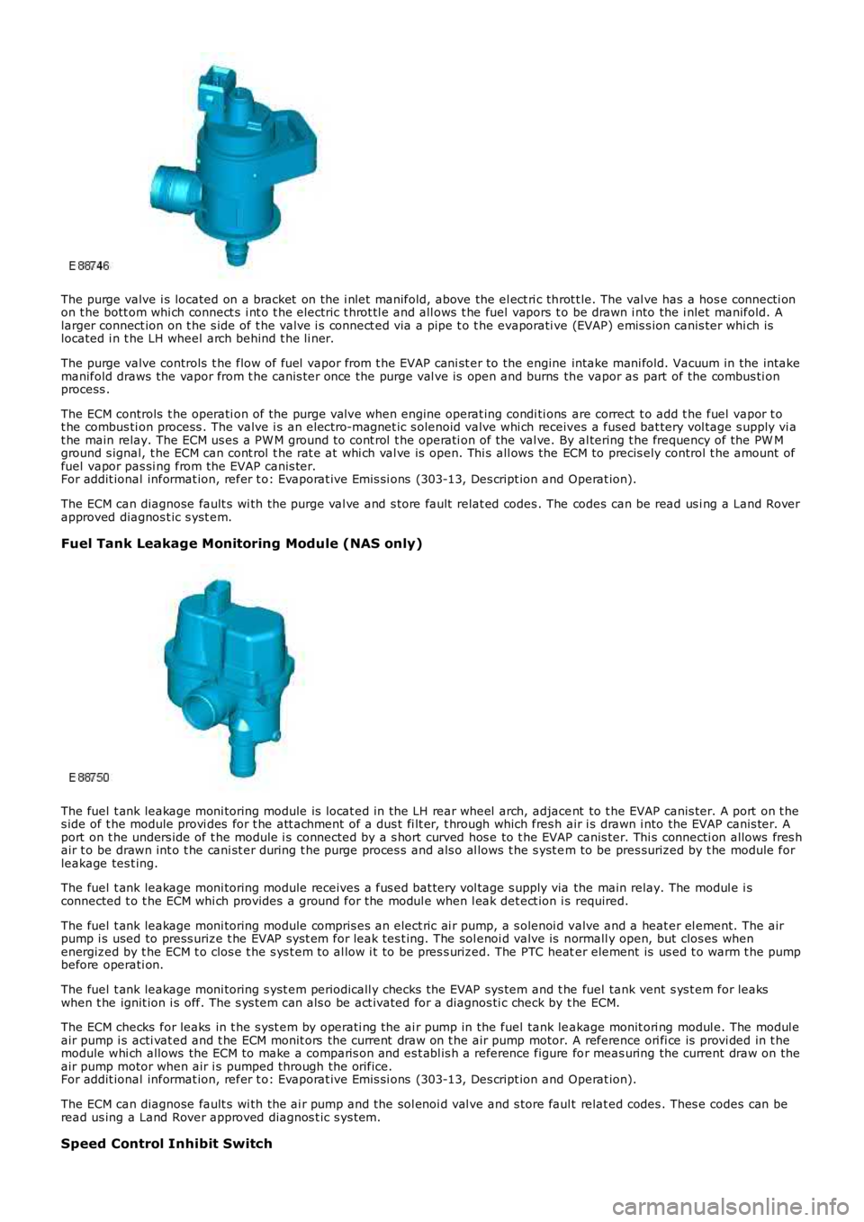
The purge valve i s located on a bracket on the i nlet manifold, above the el ect ri c throt t le. The val ve has a hos e connecti onon t he bott om whi ch connect s i nt o t he electric t hrot tl e and all ows t he fuel vapors to be drawn i nto the i nlet manifold. Alarger connect ion on t he s ide of t he valve i s connect ed via a pipe t o t he evaporati ve (EVAP) emis s ion canis ter whi ch islocated i n t he LH wheel arch behind t he li ner.
The purge valve controls t he flow of fuel vapor from t he EVAP cani st er to the engine intake mani fold. Vacuum in the intakemanifold draws the vapor from t he canis ter once the purge val ve is open and burns the vapor as part of the combus ti onprocess .
The ECM controls t he operati on of the purge val ve when engine operat ing condi ti ons are correct t o add t he fuel vapor t ot he combus ti on process . The valve i s an electro-magnet ic s olenoid valve whi ch receives a fused bat tery vol tage s upply vi at he main relay. The ECM us es a PW M ground t o cont rol t he operati on of the val ve. By al tering t he frequency of the PW Mground s ignal, t he ECM can cont rol t he rat e at whi ch val ve is open. Thi s all ows the ECM to precis ely control t he amount offuel vapor pas si ng from the EVAP canis ter.For addit ional informat ion, refer t o: Evaporat ive Emi s si ons (303-13, Des cript ion and Operat ion).
The ECM can diagnose fault s wi th the purge val ve and s tore fault relat ed codes . The codes can be read us i ng a Land Roverapproved diagnos t ic s yst em.
Fuel Tank Leakage Monitoring Module (NAS only)
The fuel t ank leakage moni toring module is l ocat ed in the LH rear wheel arch, adjacent to t he EVAP canis ter. A port on t hes ide of t he module provi des for t he att achment of a dus t fi lt er, t hrough which fres h air i s drawn i nto the EVAP canis ter. Aport on t he unders ide of t he module i s connected by a s hort curved hos e to t he EVAP canis ter. Thi s connecti on allows fres hair t o be drawn int o t he cani st er during t he purge proces s and als o al lows t he s yst em to be pres surized by t he module forleakage tes t ing.
The fuel t ank leakage moni toring module receives a fus ed bat tery vol tage s upply via the main relay. The modul e i sconnected t o t he ECM whi ch provides a ground for the modul e when l eak det ect ion i s required.
The fuel t ank leakage moni toring module compris es an elect ric ai r pump, a s olenoi d valve and a heat er el ement. The airpump i s used to press urize t he EVAP s ys t em for leak tes t ing. The sol enoi d valve is normall y open, but clos es whenenergized by t he ECM t o clos e t he s ys t em t o al low i t to be pres s urized. The PTC heater element is us ed t o warm t he pumpbefore operati on.
The fuel t ank leakage moni toring s yst em periodicall y checks the EVAP sys tem and t he fuel tank vent s ys t em for leakswhen t he ignit ion i s off. The s ys t em can als o be act ivated for a diagnos ti c check by t he ECM.
The ECM checks for leaks in t he s yst em by operati ng the ai r pump in the fuel tank leakage monit ori ng modul e. The modul eair pump i s acti vat ed and t he ECM monit ors the current draw on t he air pump motor. A reference ori fi ce is provi ded in t hemodule whi ch allows the ECM to make a comparis on and es t abl is h a reference figure for meas uring the current draw on theair pump motor when air i s pumped through the orifice.For addit ional informat ion, refer t o: Evaporat ive Emi s si ons (303-13, Des cript ion and Operat ion).
The ECM can diagnose fault s wi th the ai r pump and the sol enoi d val ve and s tore faul t relat ed codes . Thes e codes can beread us ing a Land Rover approved diagnos t ic s ys tem.
Speed Control Inhibit Switch
Page 1216 of 3229
t he fan mot ors . The fan cont rol module confi rms the fan s peed operati on on the same connect ion back t o t he ECM.
Starter Motor Relay
The s tarter mot or relay i s located in t he BJB. The operat ion of t he s tarter mot or relay i s cont rol led by t he ECM whi chprovides a ground pat h for the relay coil , energi zing t he rel ay and cl osi ng t he relay contact s. W hen the relay contacts areclos ed, bat tery vol tage i s s uppl ied, vi a t he s tarter mot or relay, to the st art er modul e s olenoid coil . The st art er s ol enoi d isenergized and connects the s t art er motor wit h a direct batt ery feed t o operate the st art er motor.
Once the engi ne has st art ed, the ECM removes the st art er motor relay ground, opening the relay contacts and t erminati ngt he bat t ery feed to the s t art er s olenoid, which i n t urn s t ops the operat ion of t he starter mot or.For addit ional informat ion, refer t o: Starti ng Sys t em - 3.2L (303-06, Des cript ion and Operat ion).
Fuel Pump Module
The fuel pump i s cont rol led by t he FPDM whi ch in t urn is control led by the ECM. The FPDM provi des pos it ive and negati vefeeds t o t he fuel pump mot or which is cont roll ed wit h a PW M out put . The fuel pump i s run for 2 s econds t o prime the fuels ys t em once igni ti on on is sens ed by t he ECM.For addit ional informat ion, refer t o: Fuel Tank and Lines (310-01, Des cri pt ion and Operati on).
Malfunction Indicator Lamp (MIL)
The MIL is locat ed in the ins trument cl us t er and is i lluminated by a CAN mes s age from t he ECM when an emis s ion relatedfaul t occurs . The ECM als o ill uminat es the MIL when reques t ed to do s o by t he TCM and t o perform a bulb check when theignit ion is s wi tched on. There is no MIL ill uminat ion for non emis si on rel ated engine management fault s . All engine faul tsare recorded wit h a Diagnos t ic Troubl e Code (DTC) whi ch can be ret rieved us ing a Land Rover approved di agnos ti c s yst em.For addit ional informat ion, refer t o: Electroni c Engi ne Controls - 3.2L (303-14, Diagnos is and Tes ti ng).
Generator Feedback Signal
The generator has a Local Interconnect Net work (LIN) bus connect ion direct to t he ECM. The LIN bus is us ed by t he ECM t oreques t vol tage for bat tery charging and t o monit or the fault s t at us of t he generat or.
PRINCIPLES OF OPERATION
Starting Process
The ECM wi ll only al low engine crank, s park and i njector functi ons when the foll owing condi ti ons are met:
A hardwi red Park/Neutral si gnal i s received from the Trans mi ss i on Cont rol Module (TCM)A hardwi red ignit ion s ignal is recei ved from t he CJBA hardwi red crank reques t s ignal is recei ved from t he CJBEncrypt ed data exchange bet ween t he ins trument cl ust er and the ECM is verifi ed.
Before the CJB will s end t he hardwired igni ti on si gnal , it mus t s ati s factori ly complet e t he fol lowi ng:
Exchange encrypt ed data wit h t he s tart control modul e t o vali dat e t he remot e handset.
Addit ional ly, before the CJB will s end t he hardwired crank reques t s ignal i t mus t receive t he fol lowing si gnal s:
Brake s ignal from t he s peed cont rol inhibi t s wit chHardwi red t rans mis s ion in Park (P) or Neutral (N) s ignal from t he s elector lever assembl y.
W i th the remote hands et ins ert ed in the s t art cont rol module and the st op/s tart button is press ed, the st art controlmodule i s sues bat tery vol tage hi gh si gnal on t he LIN bus connecti on to the CJB and the fuel pump i s run for 2 s econds t opri me t he fuel s yst em. The CJB us es this si gnal t oget her wit h t he s top l amp s wit ch signal and is sues a crank requestmes s age on the hi gh s peed CAN bus to the ECM.
The ECM, on receipt of t he crank request mess age, then provides a power and ground supply t o t he s tarter rel ay in theBJB, clos ing the relay contacts . Batt ery volt age is suppli ed via a fus e t hrough t he st art er rel ay and is pas sed to the s t art ermot or s olenoid coi l. The coil is energi zed, clos ing t he s olenoid contacts and allowing a fuse bat tery volt age supply di rectfrom the bat tery to operat e t he s tarter mot or and crank the engine and si mult aneous ly s wi tch t he fuel pump on.
The ECM operat es the st art er motor unti l the engine st art s which i s determined by t he engine s peed exceeding apre-det ermined value.
Auto St art
The ECM has an aut o s tart functi on which all ows the engi ne to cont inue cranking i f the s t op/s tart but ton is released. Thes tarter mot or will operat e unti l the engine st art s or a pre-determined peri od of ti me has el aps ed which i s bas ed on engi necool ant t emperat ure. Low engine cool ant temperat ures al low l onger crank t imes . If the engine does not rot ate or t heengi ne s peed is l ow, the ECM removes t he power s upply and ground from t he st art er rel ay st oppi ng t he crank process .
Start Prevent ion
Operat ion of t he s tart er mot or wi ll not be all owed or wil l be int errupt ed if:
t he engi ne is runni ng and t he engi ne s peed has exceeded a predet ermined s peedt he encrypt ed data exchange bet ween the i nst rument clus t er, ECM, CJB and st art control modul e has fai led t oidenti fy the remote hands ett he gear s elector l ever is not i n t he park 'P' or neutral 'N' pos it ion. The s ignal is det ermi ned from a si gnal from theTCM and al so the t rans mi ss ion mount ed pos it ion s wit cht he brake pedal i s not pres sed.
Engine Stop Process