2006 LAND ROVER FRELANDER 2 fuse
[x] Cancel search: fusePage 2486 of 3229

Publi s hed: 11-May-2011
Supplemental Restraint System - Air Bag Supplemental Restraint System
(SRS)
Diagnosi s and Tes ti ng
Principles of Operation
For a detail ed descripti on of the ai r bag s upplement al res traints sys tem, refer t o the rel evant Des cript ion and Operat ions ect ion i n t he works hop manual .REFER to: Ai r Bag and Safety Bel t Pretens ioner Suppl ement al Res t raint Sys tem (SRS) (501-20B Suppl ement al Res t rai ntSyst em, Des cript ion and Operat ion).
Inspection and Verification
W ARNING: TO AVOID ACCIDENTAL DEPLOY MENT AND POSSIBLE PERSONAL INJURY , THE BACKUP POWER SUPPLYMUST BE DEPLETED BEFORE REPAIRING OR REPLACING ANY AIR BAG SUPPLEMENTAL RESTRAINT SYSTEM (SRS)COMPONENTS. TO DEPLETE THE BACKUP POW ER SUPPLY ENERGY , DISCONNECT THE BATTERY GRO UND CABLE AND W AITTW O MINUTES. FAILURE TO FOLLOW THIS INSTRUCTION MAY RESULT IN PERSONAL INJURY .
CAUTION: Di agnos is by s ubs ti tut ion from a donor vehicle is NO T acceptabl e. Subs ti tut ion of cont rol modules doesnot guarant ee confirmat ion of a faul t, and may als o caus e addit ional fault s i n t he vehi cl e being t est ed and/or t he donorvehi cl e.
• NOTE: Given t he l egal impl icati ons of a res t raint s s ys t em fail ure, harness repairs to Air Bag module ci rcuit s are notacceptable. W here t he t ext refers to "REPAIR the circui t", t hi s wi ll normal ly mean the repl acement of a harnes s .
1. Verify t he cus t omer concern.1.
2. Vis ually ins pect for obvious s igns of damage.2.
Visual Inspection
ElectricalBatt ery condit ion, s tat e of chargeMake s ure al l elect rical connect or(s) are engaged correct ly on the ai r bag ci rcuit sW iri ng harnes sAir bag modul e(s )Make s ure the rest rai nts control modul e (RCM) is correct ly ins tall edFuse(s )Sensor(s )Pret ensi oner(s )W arning l amp bulb(s)
3. If an obvious cause for an obs erved or report ed concern is found, correct t he caus e (if pos s ible) beforeproceeding t o t he next s t ep3.
4. If t he caus e is not vis ually evi dent , check Rest rai nts Cont rol Modul e (RCM) and Occupancy Cl ass i ficat ion Syst em(OCS) module for Diagnos t ic Troubl e Codes (DTCs ) and refer t o t he DTC Index.4.
Given t he complexit y of the s ys tem and the pot enti al for damage/injury, t he preferred met hod of di agnos is i s via theManufacturer approved diagnost ic sys tem.
If the Manufacturer approved di agnos ti c s ys t em i s not avai lable, use a s can tool to ext ract DTCs and refer to the DTCIndex.
DTC Index
• NOTE: If the control modul e is sus pect and t he vehicle remains under manufact urer warranty, refer to the W arrant y Poli cyand Procedures manual (s ect ion B1.2), or determine i f any prior approval programme is i n operat ion, prior t o t heins t al lat ion of a new modul e.
• NOTE: Generic scan t ool s may not read the codes li st ed, or may read only fi ve digit codes . Mat ch the five di git s from t hes can tool to the firs t fi ve di git s of the seven digi t code l is ted to ident ify t he faul t (t he las t t wo digi ts gi ve addi ti onalinformat ion read by the manufact urer approved diagnos t ic s ys tem).
• NOTE: W hen performing el ect ri cal volt age or resi s tance tes t s, al ways us e a digit al mult imet er (DMM) accurate to threedeci mal places , and wi th an up-to-date cali brat ion cert ificate. W hen t es ti ng res is t ance, always take t he res i st ance of t heDMM leads int o account.
• NOTE: Check and recti fy bas ic faul ts before beginni ng diagnos t ic rout ines i nvol vi ng pinpoint t es t s.
• NOTE: Ins pect connect ors for s igns of water ingres s , and pins for damage and/or corros ion.
• NOTE: If DTCs are recorded and, aft er performi ng the pi npoi nt tes ts , a fault is not present , an int ermi tt ent concern maybe t he caus e. Always check for loose connect ions and corroded terminals .
For a compl ete lis t of all Di agnos ti c Trouble Codes (DTCs) t hat could be logged on this vehicle, pleas e refer to Sect ion100-00
REFER to: Di agnos ti c Trouble Code (DTC) Index - DTC: Res trai nts Cont rol Module (RCM) (100-00 General Informati on,Des cript ion and Operat ion).
Page 2725 of 3229

Contents
5
R
ENGINE COOLANT CHECK ............................ 163
BRAKE AND CLUTCH FLUID CHECK ............. 165
POWER STEERING FLUID CHECK ................ 166
WASHER FLUID CHECK ................................ 167
TECHNICAL SPECIFICATIONS ...................... 169
Vehicle battery
BATTERY WARNING SYMBOLS ................... 171
BATTERY CARE ............................................ 171
USING BOOSTER CABLES ............................ 173
CHARGING THE VE HICLE BATTERY ............. 174
CHANGING THE VE HICLE BATTERY ............. 174
Wheels and tyres
GENERAL INFORMATION ............................. 176
TYRE CARE ................................................... 177
USING WINTER TYRES................................. 183
CHANGING A ROAD WHEEL ......................... 183
TYRE REPAIR KIT ......................................... 187
USING SNOW CHAINS.................................. 192
TYRE GLOSSARY.......................................... 193
TECHNICAL SPECIFICATIONS ...................... 194
Fuses
FUSE BOX LOCATIONS ................................. 195
CHANGING A FUSE ....................................... 195
FUSE SPECIFICATION CHART....................... 196
Emergency equipment
HAZARD WARNING FLASHERS .................... 204
WARNING TRIANGLE ................................... 204
Status after a collision
DRIVING AFTER A COLLISION...................... 205
INSPECTING SAFETY SYSTEM COMPONENTS ...
206
Vehicle recovery
TOWING POINTS .......................................... 207
LASHING POINTS ......................................... 208
TRANSPORTING THE VEHICLE..................... 208
TOWING THE VEHICLE ON FOUR WHEELS .. 208
Vehicle identification
VEHICLE IDENTIFICATION PLATE................. 210
VEHICLE IDENTIFI CATION NUMBER (VIN) ... 210
VEHICLE BUILD DATE PLATE ....................... 210
Technical specifications
ENGINE SPECIFICATIONS ............................ 211
WEIGHTS...................................................... 212
DIMENSIONS................................................ 213
Type approval
Declarations of conformity ........................... 215
Audio introduction
RADIO RECEPTION....................................... 218
Audio unit overview
AUDIO UNIT OVERVIEW............................... 219
Audio unit operation
ON OR OFF CONTROL .................................. 223
VOLUME CONTROL ...................................... 223
AUDIO CONTROL ......................................... 223
WAVEBAND BUTTON ................................... 224
AUTOSTORE CONTROL ................................ 225
STATION PRESET BUTTONS ........................ 226
TRAFFIC INFORMATION CONTROL .............. 226
Audio unit menus
RADIO DATA SYSTEM (RDS) ....................... 228
REGIONAL MODE (REG) .............................. 228
ENHANCED OTHER NETWORK (RDS-EON).. 229
ALTERNATIVE FREQUENCIES ...................... 229
NEWS BROADCASTS ................................... 230
PRIORITY PROGRAMME TYPE (PTY) .......... 231
RESETTING THE AUDIO UNIT ...................... 233
Digital audio broadcasting
GENERAL INFORMATION ............................. 234
AUDIO CONTROLS ....................................... 235
DISPLAY OPTIONS ....................................... 236
CHANNEL AUTOMATIC TUNING................... 236
CHANNEL OPTIONS ..................................... 236
PRESET BUTTONS ....................................... 238
SETTINGS..................................................... 240
Compact disc player
LOADING COMPACT DISCS ......................... 245
EJECTING COMPACT DISCS ........................ 246
EJECTING MULTIPLE CO MPACT DISCS....... 246
COMPACT DISC SELECTION ........................ 246
COMPACT DISC PLAYBACK ......................... 246
Page 2915 of 3229

195
Fuses
R
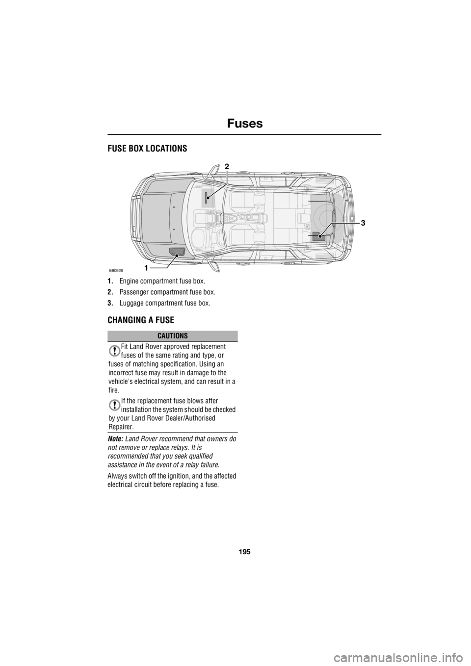
FusesFUSE BOX LOCATIONS
1. Engine compartment fuse box.
2. Passenger compartment fuse box.
3. Luggage compartment fuse box.
CHANGING A FUSE
Note: Land Rover recommend that owners do
not remove or repl ace relays. It is
recommended that you seek qualified
assistance in the event of a relay failure.
Always switch off the i gnition, and the affected
electrical circuit before replacing a fuse.
E80926
3
1
2
CAUTIONS
Fit Land Rover approved replacement
fuses of the same rating and type, or
fuses of matching spec ification. Using an
incorrect fuse may result in damage to the
vehicle's electrical system, and can result in a
fire.
If the replacement fuse blows after
installation the syst em should be checked
by your Land Rover Dealer/Authorised
Repairer.
Page 2916 of 3229

Fuses
196
L
FUSE SPECIFICATION CHART
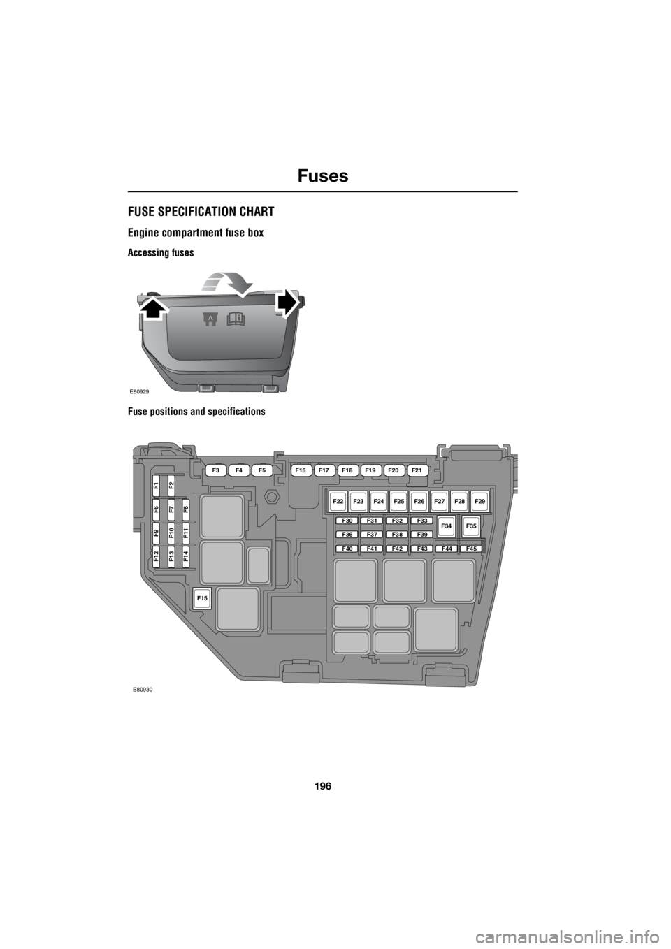
Engine compartment fuse box
Accessing fuses
Fuse positions and specifications
E80929
F22F23F24F25F26F27F28F29
F34F35F30
F36
F40
F31
F37
F41
F32
F38
F42
F33
F39
F43F44F45
F15
F12F13F14
F9F10F11
F6F7F8
F1F2
F16F17F18F19F20F21F3F4F5
E80930
Page 2917 of 3229

197
Fuses
R
Fuse number Rating (Amps) Fuse colour Circuits protected F1 5 tan Glow plugs
F2 15 blue Automatic transmission
F3 80 - Cooling fans
F4 60 - Glow plugs
F5 - - -
F6 (Diesel) 10 red Engine management F6 (Petrol) 15 blue Engine management F7 5 tan Relays
F8 (Diesel) 10 red Engine management F8 (Petrol) 15 blue Engine management
F9 (Diesel) 10 red Engine management
F9 (Petrol) 15 blue Engine management
F10 (Petrol) 10 red Engine management
F11 (Diesel) 10 red Engine management
F11 (Petrol) 10 red Engine management
F12 (Diesel) 10 red Engine management
F12 (Petrol) 20 yell ow Engine management
F13 15 blue Air Conditioning
F14 (Diesel) 15 blue Engine management
F15 40 green Starter motor
F16 (Diesel) 100 - Diesel PTC heater F17 60 - Passenger compartment fuse box supply
F18 60 - Passenger compartment fuse box supply
F19 60 - Luggage compartment fuse box supply
F20 60 - Luggage compartment fuse box supply
F21 60 - Luggage compartment fuse box supply - Audio unit
F22 30 pink Windscreen wipers
F23 - - -
Page 2918 of 3229

Fuses
198
L
F24 30 pink Headlamp washers
F25 30 pink ABS
F26 40 green ABS
F27 - - -
F28 40 green Heater blower
F29 - - -
F30 - - -
F31 15 blue Horns
F32 20 yellow Diesel auxiliary heater
F33 5 tan Relays
F34 40 green Heated windscreen(LH)
F35 40 green Heated windscreen (RH)
F36 - - -
F37 10 red Heated washer jets
F38 10 red AFS (RH lamp motors)
F39 10 red Climate control
F40 - - -
F41 20 yellow Passenger compartment fuse box supply
F42 15 blue Engine management
F43 5 tan Headlamp levelling control - AFS
F44 10 red AFS (LH lamp motors)
F45 15 blue Cigar lighter
Fuse number Rating (Amps) Fuse colour Circuits protected
Page 2919 of 3229

199
Fuses
R
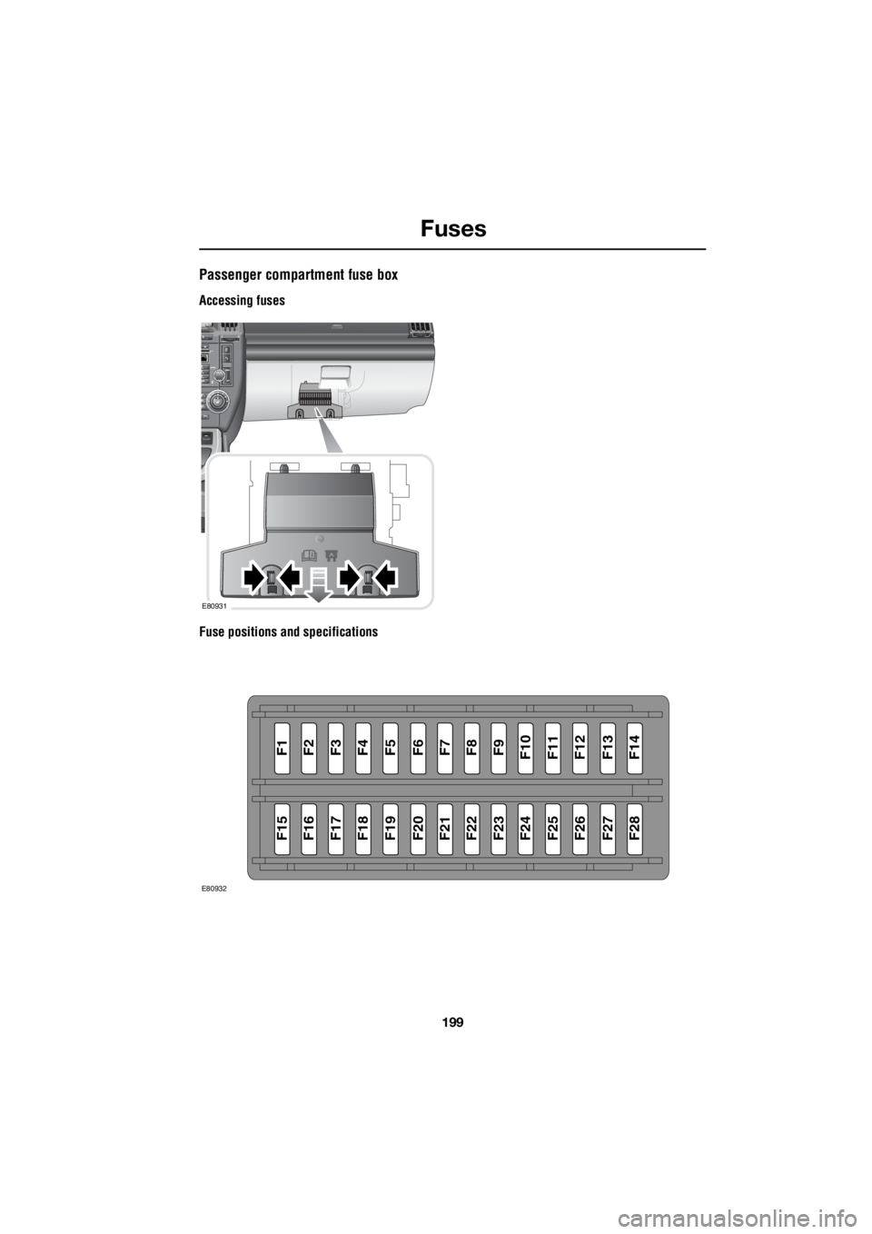
Passenger compartment fuse box
Accessing fuses
Fuse positions and specifications
E80931
F1F2F3F4F5F6F7F8F9F10F11F12F13F14
F15F16F17F18F19F20F21F22F23F24F25F26F27F28
E80932
Page 2920 of 3229

Fuses
200
L
Fuse number Rating (Amps) Fuse co lour Circuits protected
F1 5 tan Rain sensor
F2 10 red SRS
F3 5 tan ABS
F4 5 tan Instrument pack - Accelerator pedal - Light
Switch Module
F5 - - -
F6 15 blue Audio unit
F7 7.5 brown Steering wheel controls
F8 5 tan Instrument pack
F9 15 blue Headlamp main beam
F10 15 blue Sunroof
F11 7.5 brown Reverse lights and interior mirror dip
F12 - - -
F13 15 blue Front fog lamps
F14 15 blue Screen wash
F15 - - -
F16 - - -
F17 7.5 brown Interior lighting
F18 - - -
F19 5 tan Electric seat adjustment
F20 15 blue Rear wiper
F21 5 tan Alarm
F22 20 yellow Fuel pump
F23 20 yellow Steering column lock
F24 - - -
F25 10 red Tailgate - Fuel filler flap
F26 5 tan Diagnostic socket and alarm
F27 5 tan Start button and climate control
F28 5 tan Brake lights