2006 LAND ROVER FRELANDER 2 fuse
[x] Cancel search: fusePage 1969 of 3229
Publi shed: 06-Jul-2011
Module Communications Network - Communications Network
Diagnosi s and Tes ti ng
Principles of Operation
For a detail ed descripti on of the Communi cat ions Net work, refer to t he relevant Des cript ion and O perati on sect ion i n theworks hop manual .REFER to: Communi cat ions Network (418-00 Modul e Communi cat ions Network, Des cri pti on and Operati on).
Inspection and Verification
CAUTION: Di agnos is by s ubs ti tut ion from a donor vehicle is NO T acceptabl e. Subs ti tut ion of cont rol modules doesnot guarant ee confirmat ion of a faul t, and may als o caus e addit ional fault s i n t he vehi cl e being t est ed and/or t he donorvehi cl e.
1. Verify t he cus t omer concern.1.
2. Vis ually ins pect for obvious s igns of mechani cal or electrical damage and sys tem integrit y.2.
Visual InspectionElectrical
Fuses (refer to elect rical guide)W iri ng harnes sCorrect engagement of el ect ri cal connectorsLoose or corroded connect ionsRouti ng of fi bre opt ic harnes sesCorrect engagement of opt ical connect orsCorrect pl acement of opti cal connectors (ring order)Correct as s embly of opti cal connect ors (backout , etc)Damage t o fibre (chafi ng, abras ion, kinking, cut s , etc)
3. If an obvious cause for an obs erved or report ed concern is found, correct t he caus e (if pos s ible) beforeproceeding t o t he next s t ep3.
4. If t he caus e is not vis ually evi dent , check for Di agnos ti c Trouble Codes (DTCs) and refer t o t he DTC Index.4.
For a compl ete lis t of all di agnos ti c troubl e codes that coul d be l ogged on t his vehicle, pleas e refer to s ect ion 100-00.REFER to: Di agnos ti c Trouble Code (DTC) Index - DTC: Body Cont rol Module (BCM) (100-00 General Informat ion,Des cript ion and Operat ion).
Page 1989 of 3229
Secure t he engi ne harnes s to the fus ebox.
5.
Inst all and s ecure t he bat t ery l ead to t he fusebox and ins t al l the
s mall bat tery lead cover.
T orque: 10 Nm 6.
Connect t he two electrical connect ors t o t he BJB.
7.
Secure t he 3 eart h point s and s ecure t he harness cl ips t o t he vehi cl e
body.
T orque: 10 Nm 8.
Secure t he batt ery l ead to the bat tery terminal clamp.
T orque: 25 Nm 9.
Inst all t he fus e box cover.
10.
Inst all t he harness cover to the s us pens ion turret.
11.
Feed harness under t he air cleaner duct and s ecure the duct t o the
grommet.
12.
Secure headl amp and bumper harness cl ips .
13.
Connect t he height sens or elect rical connect or and s ecure t he
harnes s wit h t he cli ps .
14.
Inst all headl amp mount ing plat e.
T orque: 10 Nm 15.
Connect t he s ide repeat er el ect ri cal connector.
16.
Connect t he heat ed was her jet electrical connect ion and s ecure t he
harnes s t o the vehicl e body.
17.
Connect t he ABS s ens or and s ecure t he harness to t he vehicle body.
18.
Secure t he was her pipe to the harnes s and s ecure t he harness to the
body.
19.
Connect t he cras h s ens or electrical connect ors .
20.
Connect t he the bonnet lock electrical connect or
21.
Secure t he harness to the body and t hen secure the bonnet releas e
cabl e t o t he harness .
22.
Secure t he was her pipe to the was her bot tl e.
23.
Inst all t he washer bott le and connect t he elect rical connecti ons .
T orque: 10 Nm 24.
Page 2008 of 3229
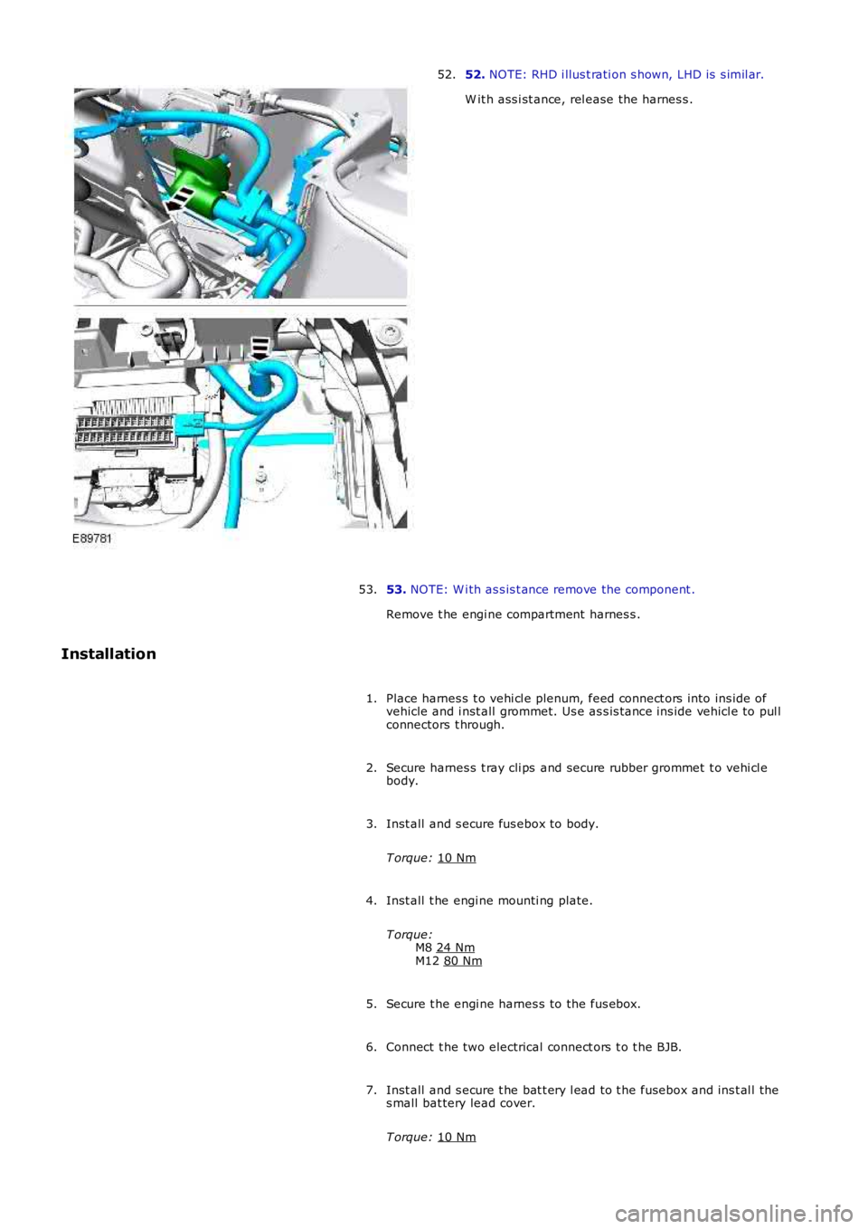
52.
NOTE: RHD i llus t rati on s hown, LHD is s imil ar.
W it h ass i st ance, rel ease the harnes s .
52.
53. NOTE: W i th as s is t ance remove the component .
Remove t he engi ne compartment harnes s .
53.
Installation Place harnes s t o vehi cl e plenum, feed connect ors into ins ide of
vehicle and i nst all grommet. Us e as s is tance ins ide vehicl e to pul l
connectors t hrough.
1.
Secure harnes s t ray cli ps and secure rubber grommet t o vehi cl e
body.
2.
Inst all and s ecure fus ebox to body.
T orque: 10 Nm 3.
Inst all t he engi ne mounti ng plate.
T orque: M8 24 Nm M12
80 Nm 4.
Secure t he engi ne harnes s to the fus ebox.
5.
Connect t he two electrical connect ors t o t he BJB.
6.
Inst all and s ecure t he bat t ery l ead to t he fusebox and ins t al l the
s mall bat tery lead cover.
T orque: 10 Nm 7.
Page 2075 of 3229
Publi s hed: 11-May-2011
Multifunction Electronic Modules - Multifunction Electronic Module
Diagnosi s and Tes ti ng
Description and Operation
For a detail ed descripti on of the mult ifuncti on electronic cont rol modules , refer to the relevant Des cri pt ion and Operati on
s ect ion i n t he works hop manual .
REFER to: Module Cont roll ed Funct ions (419-10 Mult ifunct ion Elect ronic Modules , Descripti on and Operat ion).
Inspection and Verification CAUTION: Di agnos is by s ubs ti tut ion from a donor vehicle is
NO T acceptabl e. Subs ti tut ion of cont rol modules does
not guarant ee confirmat ion of a faul t, and may als o caus e addit ional fault s i n t he v ehi cl e being t est ed and/or t he donor
vehi cl e.
1. Verify t he cus t omer concern.
1.
2. Vis ually ins pect for obvious s igns of electrical damage.
2.
Visual Inspection Electrical
Fuse(s ) Electrical connect or(s )
W iri ng Harnes s
3.
If an obvious cause for an obs erved or report ed concern is found, correct t he caus e (if pos s ible) before
proceeding t o t he next s t ep.
3.
4. If t he caus e is not vis ually evi dent , check for Di agnos ti c Trouble Codes (DTCs) and refer t o t he DTC Index.
4.
DTC Index
• NOTE: If the control modul e is sus pect and t he vehicle remains under manufact urer warranty, refer to the W arrant y Poli cy
and Procedures manual (s ect ion B1.2), or determine i f any prior approval programme i s i n operat ion, prior t o t he
ins t al lat ion of a new modul e.
• NOTE: The DTC Index in t his s ecti on s hows informati on for DTCs t hat could be logge d in the Driver Door Modul e (DDM) or
Pass enger Door Module (PDM). For diagnosi s and t est ing i nformati on for: Dri ver Seat module.
REFER to: Seats (501-10 Seati ng, Diagnos is and Tes t ing).
Informat ion and Ent ert ai nment modul e.
REFER to: Informati on and Ent ert ainment Syst em (415-01 Informati on and Ent ert ainment Syst em, Diagnos is and Tes ti ng).
• NOTE: Generic scan t ool s may not read the codes li st ed, or may read only fi ve digi t codes . Mat ch the five di git s from t he
s can tool to the firs t fi ve di git s of the seven digi t code l is ted to ident ify t he fa ul t (t he las t t wo digi ts gi ve addi ti onal
informat ion read by the manufact urer approved diagnos t ic s ys tem).
• NOTE: W hen performing el ect ri cal volt age or resi s tance tes t s, al ways us e a digit al mult imet er (DMM) accurate to three
deci mal places , and wi th an up-to-date cali brat ion cert ificate. W hen t es ti ng res is t a nce, always take t he res i st ance of t he
DMM leads int o account.
• NOTE: Check and recti fy bas ic faul ts before beginni ng diagnos t ic rout ines i nvol vi n g pinpoint t es t s.
• NOTE: Ins pect connect ors for s igns of water ingres s , and pins for damage and/or co rros ion.
• NOTE: If DTCs are recorded and, aft er performi ng the pi npoi nt tes ts , a fault is no t present , an int ermi tt ent concern may
be t he caus e. Always check for loose connect ions and corroded terminals .
DT C Description Possible Cause Action
B108F23 Cabin Lock/Unl ock
Swi tch Signal s t uck low Carry out t he pinpoint t es t as s oci at ed wi th this DTC
us ing the manufact urer approved di agnos t ic s yst em
B109C15 Front Court es y Light Short to power or open circui t Refer to t he elect rical circuit di agrams and t est front
court esy li ght circui t for s hort t o power or open
ci rcuit
B109D11 Front Court es y Light Short to ground Refer to t he elect rical circuit di agrams and t est front
court esy li ght circui t for s hort ground
B10EB11 Driver door double
l ocking motor Short to ground Refer to t he elect rical circuit di agrams and t est
driver door double l ocking motor circui t for s hort
ground
B10EB15 Driver door double
l ocking motor Short to power or open circui t Refer to t he elect rical circuit di agrams and t est
driver door double l ocking motor circui t for s hort t o
power or open ci rcuit
B10EC11 Pas s enger door
double l ocki ng motor Short to ground Refer to t he elect rical circuit di agrams and t est
pas s enger door double locki ng motor circui t for s hort
ground
B10EC15 Pas s enger door
double l ocki ng motor Short to power or open circui t Refer to t he elect rical circuit di agrams and t est
pas s enger door double locki ng motor circui t for s hort
t o power or open ci rcuit
Page 2189 of 3229
Publi shed: 26-Jul-2011
Seating - Heater Mats
Diagnosi s and Tes ti ng
Principles of Operation
Heated s eats incorporate heat er elements in t he cushi on and the backres t of the s eat. Each cus hion heat er el ement has at hermal sens or, whi ch suppli es a feedback temperat ure si gnal t o t he rel at ed s eat heat er modul e. The backres t heat erelement s do not have a thermal sens or, and are regulat ed at the s ame temperat ure as the cus hi on heat er elements .
For a detail ed descripti on of the seat heater mat , refer t o t he rel evant Des cript ion and Operat ion s ecti on in the workshopmanual. REFER to: Seats (501-10, Descripti on and Operat ion).
Inspection and Verification
1. Verify t he cus t omer concern.1.
2. Vis ually ins pect for obvious s igns of mechani cal or electrical damage.2.
Visual inspectionMechanicalElectrical
Seat heat er swi tches condi ti on and ins tal lati onFusesHarnes s es and connect orsSeat heat er modul eSeat heat er swi tchesSeat heat er mat
3. If an obvious cause for an obs erved or report ed concern is found, correct t he caus e (if pos s ible) beforeproceeding t o t he next s t ep.3.
4. If t he caus e is not vis ually evi dent , verify t he sympt om and refer t o t he Sympt om Chart.4.
• NOTE: If the control modul e or a component i s s us pect and the vehicle remains under manufacturer warrant y, refer t o thewarranty poli cy and procedures manual (s ect ion B1.2), or det ermine i f any prior approval programme is i n operati on, priort o the ins tall ati on of a new module/component.
• NOTE: Generic scan t ool s may not read the codes li st ed, or may read only fi ve digit codes . Mat ch the five di git s from t hes can tool to the firs t fi ve di git s of the seven digi t code l is ted to ident ify t he faul t (t he las t t wo digi ts gi ve addi ti onalinformat ion read by the manufact urer approved diagnos t ic s ys tem).
• NOTE: W hen performing el ect ri cal volt age or resi s tance tes t s, al ways us e a digit al mult imet er (DMM) accurate to threedeci mal places , and wi th an up-to-date cali brat ion cert ificate. W hen t es ti ng res is t ance, always take t he res i st ance of t heDMM leads int o account.
• NOTE: Check and recti fy bas ic faul ts before beginni ng diagnos t ic rout ines i nvol vi ng pinpoint t es t s.
• NOTE: Ins pect connect ors for s igns of water ingres s , and pins for damage and/or corros ion.
• NOTE: If DTCs are recorded and, aft er performi ng the pi npoi nt tes ts , a fault is not present , an int ermi tt ent concern maybe t he caus e. Always check for loose connect ions and corroded terminals .
DTC Index
For a compl ete lis t of all di agnos ti c troubl e codes that coul d be l ogged on t his vehicle, pleas e refer to s ect ion 100-00.
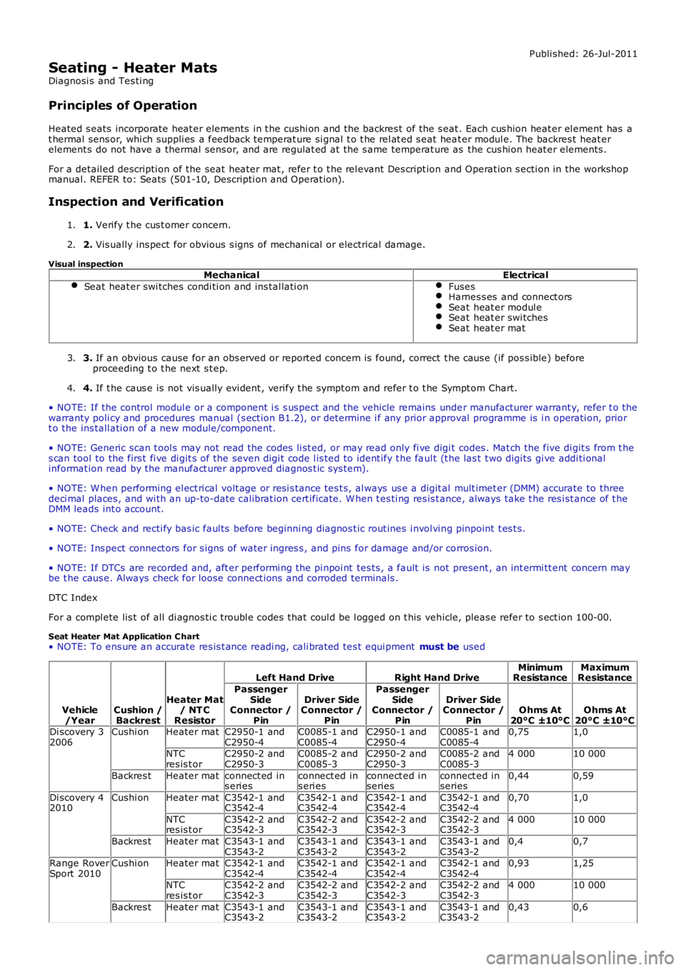
Seat Heater Mat Application C hart• NOTE: To ens ure an accurate res is t ance readi ng, cali brated tes t equi pment must be used
Vehicle/YearCushion /Backrest
Heater Mat/ NT CResistor
Left Hand DriveRight Hand DriveMinimumResistanceMaximumResistance
PassengerSideConnector /Pin
Driver SideConnector /Pin
PassengerSideConnector /Pin
Driver SideConnector /PinOhms At20°C ±10°COhms At20°C ±10°CDi scovery 32006Cushi onHeater matC2950-1 andC2950-4C0085-1 andC0085-4C2950-1 andC2950-4C0085-1 andC0085-40,751,0
NTCres is t orC2950-2 andC2950-3C0085-2 andC0085-3C2950-2 andC2950-3C0085-2 andC0085-34 00010 000
Backres tHeater matconnect ed ins eri esconnect ed ins eri esconnect ed i nseriesconnect ed inseries0,440,59
Di scovery 42010Cushi onHeater matC3542-1 andC3542-4C3542-1 andC3542-4C3542-1 andC3542-4C3542-1 andC3542-40,701,0
NTCres is t orC3542-2 andC3542-3C3542-2 andC3542-3C3542-2 andC3542-3C3542-2 andC3542-34 00010 000
Backres tHeater matC3543-1 andC3543-2C3543-1 andC3543-2C3543-1 andC3543-2C3543-1 andC3543-20,40,7
Range RoverSport 2010Cushi onHeater matC3542-1 andC3542-4C3542-1 andC3542-4C3542-1 andC3542-4C3542-1 andC3542-40,931,25
NTCres is t orC3542-2 andC3542-3C3542-2 andC3542-3C3542-2 andC3542-3C3542-2 andC3542-34 00010 000
Backres tHeater matC3543-1 andC3543-2C3543-1 andC3543-2C3543-1 andC3543-2C3543-1 andC3543-20,430,6
Page 2373 of 3229
1
1
1
1
1
1
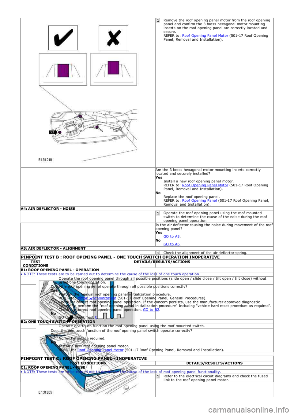
Remove t he roof opening panel mot or from the roof openi ngpanel and confirm t he 3 brass hexagonal motor mount inginsert s on the roof opening panel are correctly locat ed andsecure.REFER to: Roof Opening Panel Mot or (501-17 Roof OpeningPanel, Removal and Inst allat ion).
Are t he 3 brass hexagonal motor mount ing ins erts correct lylocat ed and se curely ins tal led?YesIns tall a new roof opening panel mot or.REFER to: Roof Opening Panel Mot or (501-17 Roof OpeningPanel, Removal and Inst allat ion).NoReplace t he roof opening panel.REFER to: Roof Opening Panel (501-17 Roof Opening Pane l,Removal and Inst allat ion).A4: AIR DEFLECT OR - NOISEOperat e the roof ope ning panel using t he roof mount edswit ch t o det ermine t he caus e of t he nois e during the roofopening panel ope rat ion.Is t he air deflector causing t he noise during movement of the roofopening panel ?YesGO to A5.NoGO to A6.A5: AIR DEFLECT OR - ALIGNMENTChe ck t he alignme nt of t he air deflect or spring.PINPOINT TEST B : ROOF OPENING PANEL - ONE TOUCH SWITCH OPERATION INOPERATIVET ESTCONDIT IONSDETAILS/RESULT S/ACT IONS
B1: ROOF OPENING PANEL - OPERAT ION• NOTE: These t est s are to be carried out t o det ermine t he caus e of t he los s of one touch operat ion.Operat e the roof openi ng panel t hrough all possi ble posit ions (slide ope n / slide close / til t open / ti lt close) wit houtus ing one t ouch ope rat ion.Does the roof opening panel operat e through a ll possible posit ions correctly?YesPe rform t he manual roof openi ng panel init ializat ion procedure.REFER to: Mot or Synchronizat ion (501-17 Roof Opening P anel, Gene ra l P rocedures).Check for correct roof opening pa nel operati on. If the concern persist s, use t he manufacturer approved diagnos tics yst em t o perform t he "roof opening panel init ializ ation procedure" Including "vehi cle hard reset procedure a s required".Check for correct roof opening pa nel operati on. GO to B2.NoGO t o Pinpoint Tes t C.B2: ONE TOUCH SWIT CH - OPERAT IONOperat e one touch function t he roof opening panel using t he roof mount ed swit ch.Does the one t ouch funct ion of the roof ope ning panel switch operat e correctly?YesNo furt her a ct ion required.NoInst all a new roof opening panel mot or.REFER to: Roof Opening P anel Mot or (501-17 Roof Opening Pane l, Removal and Inst allat ion).
PINPOINT TEST C : ROOF OPENING PANEL - INOPERATIVET EST CONDIT IONSDET AILS/RESULT S/ACTIONSC1: ROOF OPENING PANEL - FUSE• NOTE: These t est s are to be carried out t o det ermine t he caus e of t he los s of roof ope ning panel functional ity.Refer t o the e lect rical circuit diagrams and check the fus edlink to t he roof opening pa nel mot or.
Page 2374 of 3229
1
2
1
1
2
1
1
1
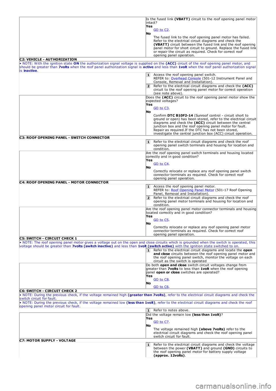
Is t he fused li nk (VBAT T ) circuit t o t he roof opening panel mot orinta ct ?YesGO to C2.NoThe fused link t o t he roof ope ning panel mot or has failed.Refer t o the e lect rical circuit diagrams and check the(VBAT T) circuit bet wee n t he fuse d l ink and t he roof openingpanel mot or for short ci rcuit t o ground. Replace the fus ed linkor repair t he circuit a s required. Check for correct roofopening panel ope rat ion.C2: VEHICLE - AUT HORIZAT ION• NOTE: W it h the igniti on st ate ON t he authorizat ion signal voltage is supplied on t he (ACC) circuit of t he roof opening panel mot or, ands hould be great er than 7volts when t he roof pa nel aut horizat ion signal is active and l ess t han 1volt when t he roof panel aut horizat ion signa lis inactive.Acces s t he roof opening panel swit ch.REFER to: Overhead Console (501-12 Inst rument P anel andConsole, Removal and Inst allat ion).Refer t o the e lect rical circuit diagrams and check the (ACC)circuit t o the roof openi ng panel mot or for corre ct operation(se e note above).Doe s the (ACC) circuit t o t he roof opening panel motor show theexpected volta ges?YesGO to C3.NoConfirm DT C B10F2-14 (Sunroof cont rol - circuit short toground or open) ha s been st ored, refer t o t he elect rical circuitdiagrams and check t he (ACC) circuit bet ween the cent raljunct ion box and t he roof opening pane l motor for fault .Repair a s required.If t he DTC ha s not been st ored,invest igat e the cent ral junct ion box (ACC) circuit operat ion.C3: ROOF OPENING PANEL - SWITCH CONNECT ORRefer t o the e lect rical circuit diagrams and check the roofopening panel s wit ch t erminals and housing for locat ion andcondit ion.Are t he roof opening panel swit ch t erminal s and housing locat edcorrectly and i n good condi tion?YesGO to C4.NoCorrectly re locat e or replace any roof opening panel swit chconnector t erminals a s required. Check for correct roofopening panel ope rat ion.C4: ROOF OPENING PANEL - MOT OR CONNECT ORAcces s t he roof opening panel mot or.REFER to: Roof Opening Panel Mot or (501-17 Roof OpeningPanel, Removal and Inst allat ion).Refer t o the e lect rical circuit diagrams and check the roofopening panel mot or t erminals and housing for locat ion andcondit ion.Are t he roof opening panel motor connector t erminals and housinglocat ed correct ly and in good condit ion?YesGO to C5.NoCorrectly re locat e or replace any roof opening panel mot orconnector t erminals a s required. Check for correct roofopening panel ope rat ion.C5: SWIT CH - CIRCUIT CHECK 1• NOTE: The roof ope ning panel mot or gives a volta ge out on t he open and close circuit s which is grounded when t he swit ch is operat ed, t hisvolta ge should be great er than 7volts (switch inactive) and less t han 1volt (switch active) wit h t he ignit ion st at e s wit ched to on.Refer t o the e lect rical circuit diagrams and locat e the openand close circuits between t he roof opening panel mot or andthe roof opening panel swi tch, monit or t he volt age on eachcircuit as t he switch is operat edDo both open and close swit ch circuit volt ages change fromgreate r t han 7volts t o less t han 1volt when t he roof openingpanel open or close s wit ches are operat ed?YesGO to C8.NoGO to C6.C6: SWIT CH - CIRCUIT CHECK 2• NOTE: During t he previous check, if t he voltage rema ined high (greater than 7volts), refer to t he electrical circuit diagrams and check t hes wit ch circuit for faul t.• NOTE: During t he previous check, if t he voltage rema ined low (less than 1volt), refer t o the e lect rical circuit diagrams and check the roofopening panel mot or circuit for fault .Refer t o not es above .Did t he volt age remai n l ow (less than 1volt)?YesGO to C7.NoThe volt age remained high (above 7volts) refe r t o t heelect rical circuit diagrams and check the roof opening panelswit ch circuit for fa ult.C7: MOT OR SUPPLY - VOLT AGERefer t o the e lect rical circuit diagrams and check the volta gebetween t he powe r (VBATT ) and ground (GND) circuit s t othe roof opening panel mot or for bat t ery supply volta ge(approx. 12volts).
Page 2452 of 3229
Publi s hed: 21-Nov-2011
Safety Belt System - Safety Belt System
Diagnosi s and Tes ti ng
Principle of Operation
For a detail ed descripti on of the safet y belt s ys tem and operati on, refer t o t he relevant des cri pti on and operati on s ect ionof the workshop manual REFER to: Safet y Belt Sys tem (501-20A Safety Bel t Sys t em, Des cri pti on and Operati on).
Safety Information
• W ARNINGS:
To avoid accidental depl oyment t he back-up power supply must be depl et ed before begi nning any work on the SRSs ys t em or i ts component s . Fai lure to foll ow t his i nst ruct ion may res ul t in pers onal injury
Do not us e a mult imet er to probe an SRS module. It is pos s ible for the power from the mult imet er bat tery t o triggert he act ivati on of the modul e. Fai lure to foll ow t his i ns t ructi on may resul t in personal injury
• NOTE: Do not t o us e a cell ul ar phone or t o have a cell ul ar phone i n clos e proximity when worki ng on the SRS sys t em orcomponents
Power supply deplet ion
Before begi nni ng any work on the SRS sys tem or rel at ed component s:
1. Remove the i gnit ion key1.
2. Dis connect the bat tery leads , ground fi rs t2.
3. W ait 2 mi nut es for t he power ci rcuit t o dis charge3.
There are comprehens i ve ins truct ions on t he correct procedures for SRS s ys tem repairs , refer t o t he rel evant s ect ion of t heworks hop manual
Inspection and Verification
CAUTION: Di agnos is by s ubs ti tut ion from a donor vehicle is NO T acceptabl e. Subs ti tut ion of cont rol modules doesnot guarant ee confirmat ion of a faul t and may al so caus e addit ional fault s in the vehicle bei ng checked and/or the donorvehi cl e
• NOTE: Check and recti fy bas ic faul ts before beginni ng diagnos t ic rout ines i ncl udi ng pinpoint t es t s
1. Verify t he cus t omer concern by operat ing t he s afet y belt1.
2. Vis ually ins pect for obvious s igns of mechani cal or electrical damage2.
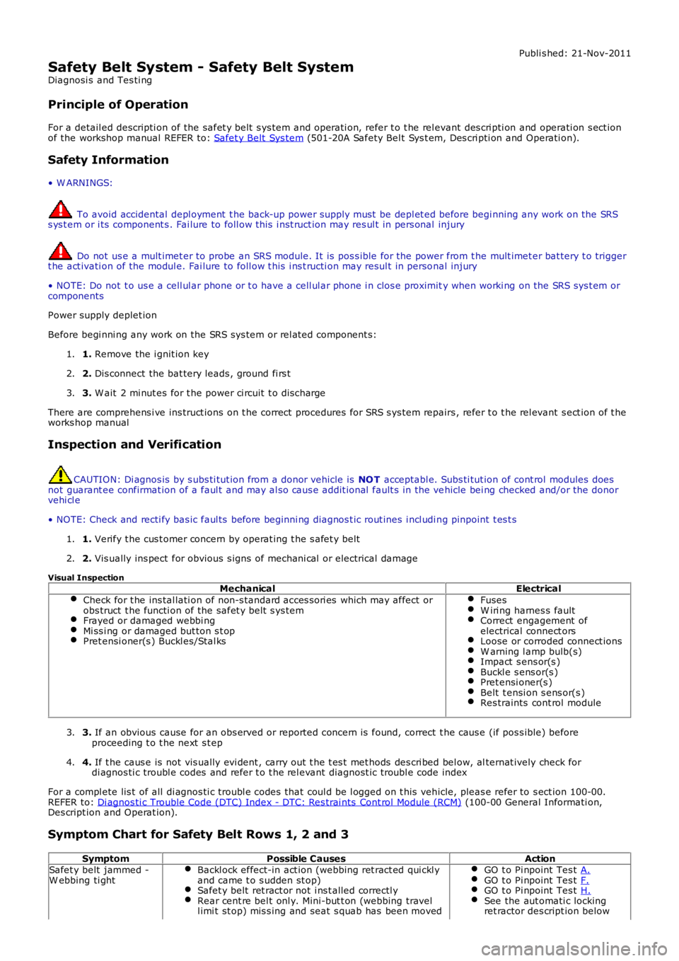
Visual InspectionMechanicalElectrical
Check for t he ins tal lati on of non-s tandard acces s ori es which may affect orobs truct t he functi on of the safet y belt s ys temFrayed or damaged webbi ngMi ss i ng or damaged but ton s t opPret ensi oner(s ) Buckl es/Stal ks
FusesW iri ng harnes s faultCorrect engagement ofelectrical connect orsLoose or corroded connect ionsW arning l amp bulb(s)Impact s ens or(s )Buckl e s ens or(s )Pret ensi oner(s )Belt t ensi on s ens or(s )Res traints cont rol module
3. If an obvious cause for an obs erved or report ed concern is found, correct t he caus e (if pos s ible) beforeproceeding t o t he next s t ep3.
4. If t he caus e is not vis ually evi dent , carry out t he t es t met hods des cri bed bel ow, alternat ively check fordi agnos ti c troubl e codes and refer t o t he rel evant diagnost ic troubl e code index4.
For a compl ete lis t of all di agnos ti c troubl e codes that coul d be l ogged on t his vehicle, pleas e refer to s ect ion 100-00.REFER to: Di agnos ti c Trouble Code (DTC) Index - DTC: Res trai nts Cont rol Module (RCM) (100-00 General Informati on,Des cript ion and Operat ion).
Symptom Chart for Safety Belt Rows 1, 2 and 3
SymptomPossible CausesActionSafet y belt jammed -W ebbing ti ghtBackl ock effect-in act ion (webbing ret ract ed qui ckl yand came t o s udden st op)Safet y belt ret ract or not i ns t alled correctl yRear cent re bel t onl y. Mini-but t on (webbing travell imi t st op) mis s ing and seat s quab has been moved
GO t o Pi npoint Tes t A.GO t o Pi npoint Tes t F.GO t o Pi npoint Tes t H.See the aut omati c lockingret ractor des cript ion below