2006 LAND ROVER FRELANDER 2 engine coolant
[x] Cancel search: engine coolantPage 44 of 3229
Publi s hed: 11-May-2011
General Information - Road/Roller Testing
Des cript ion and Operat ion
Road or roll ing road t es t ing may be carri ed out for various reasons and a procedure det ail ing pre-t es t checks , throughengi ne s tarti ng and s topping, pre-driving checks , on-t es t checks to final checks on complet ion of t he tes t are given.
Unles s complete vehi cl e performance is bei ng checked, t he ful l road t est procedure need not be carried out . Ins tead, t hos eit ems part icularly relevant t o t he s yst em(s) bei ng checked can be ext racted.
Pre-Test Checks
W ARNING: If t he brake s yst em hydraul ic fluid level i s l ow, pedal travel i s exces si ve or a hydraulic leak is found, donot att empt to road t est t he vehicle unt il t he reas on for t he low fl ui d l evel, excess ive pedal travel or hydraulic leak isfound and rect ified.
It is s ugges t ed that pre-t es t and funct ional t es ts of t hose sys tems/circuit s whi ch affect t he safe and l egal operati ons oft he vehi cl e, s uch as brakes , light s and s teeri ng, should al ways be carri ed out before the road or roll ing road tes t .
Engi ne oil l evelEngi ne cool ant levelTires, for correct pres sure, compat ible types and tread patt erns , and wear wi thi n limi ts .There i s s ufficient fuel in the t ank to compl ete the t est .Check al l around the engine, t rans mis s ion and under the vehicle for oil , coolant , hydraul ic and fuel l eaks . Make anote of any apparent leaks and wipe off t he surrounding areas t o make it easi er to identi fy t he extent of the leakon complet ion of t he tes t.
Starting the Engine
• NOTE: On i nit ial dri ve away from cold and wit hi n t he fi rs t 1.5 km (1 mile), do not depress accelerat or pedal beyond halft ravel unt il t he vehi cl e has att ained a minimum s peed of 25 km/h (15 mil es /h). Never operat e at high engi ne speed or wi tht he accelerat or pedal at ful l travel whil st the engine i s cold.
With the ignition off, check:
The parking brake is appli ed.Automatic transmission: The s el ect or lever is i n 'P' - PARK.Manual transmission: The gear l ever i s in NEUTRAL.All i ns t rument gauges read zero.
With the ignition on, check:
Igni ti on cont roll ed warni ng li ght s come on.Engi ne t emperature gauge regis t ers a readi ng compat ibl e wi th t he engine t emperat ure.Fuel gauge regi st ers a reading appropriate to the fuel l evel i n t he tank.The operati on of the parki ng brake warning l ight and fl ui d l evel warni ng indicator light.
On Road Test Check:
CAUTION: At commencement of road tes ti ng, check the brake operati on while s ti ll travel li ng at low speed beforecont inuing wit h t he tes t. If t he brakes pul l to one si de, or appear to be ot herwi se fault y, do not cont inue wit h t he roadt es t unti l the fault has been found and rect ified.
The parking brake releas es completel y.Gear changing i s s mooth, and t here are no abnormal noi s es or vi brati ons from t he t rans mis s ion.The engi ne power out put is s ati s factory, accel erati on is smoot h and accel erator pedal operat ion is not s ti ff orheavy, and engi ne s peed ret urns t o idl e correctl y.There i s no exces s ive or abnormall y colored s moke from t he engi ne under normal driving, heavy l oad or overruncondi ti ons .Steering operat ion i s s moot h, accurat e, not exces s ively heavy or wit h exces s ive free pl ay or vibrat ion. Does not pul lt o one s ide and s elf centres smoot hly after corneri ng.All i ns t rument s regis t er the correct readi ngs and operate correctl y.Swit ches and controls operat e s moothl y and posi ti vel y, warning or i ndi cat or light s operate correctl y and thedirect ion i ndi cat or cont rol s elf cancels when the s t eering i s ret urned t o t he s traight ahead pos it ion.Heati ng and vent il at ion sys tems work correct ly and effect ively.Brakes operate efficientl y.
Brake Testing
Avoi d brake t es ti ng on busy roads where i t can caus e i nconveni ence or danger t o ot her road users.
CAUTION: Brake t es ti ng which i ncludes heavy brake appl icati ons should not be carri ed out wit h new brake pads /dis csunti l the component s have bedded-i n. New brake fri ct ion component s wi ll not reach ful l efficiency unt il t he beddi ng-inprocess is complet e. Not e t hat when new parking brake shoes or rear brake di scs have been ins t al led, it i s es sent ial thatt he 'beddi ng-in' procedure i s carri ed out.For addit ional informat ion, refer t o: Parking Brake Shoes Bedding-In (206-05 Parking Brake and Actuati on, GeneralProcedures).
Test t he brakes at s everal speeds wit hin the normal operat ing range usi ng both light and heavy pedal pres s ure. Note anyt endency to snat ch, pull or drag, and any undue del ay in appli cat ion or release.
Page 171 of 3229

Publi s hed: 11-May-2011
Maintenance Schedules - Maintenance Schedules - Gasoline Engines
Des cript ion and Operat ion
Under Bonnet View
ItemPart NumberDescription1-Coolant expans ion t ank
2-Brake flui d res ervoir (LH drive i llus t rated - RH dri ve on oppos i te si de)
3-Engine oi l fil ler cap4-Power s teeri ng res ervoir
5-Engine oi l l evel i ndi cat or
6-W indscreen washer fl uid res ervoi r
Maintenance Operations
CAUTION: Not e that t he 'A' and 'B' Service Interval s li s ted on the 'Maintenance Check Sheet' for vehicles operat ingunder arduous condi ti ons , vary from t hos e s pecifi ed for vehicles operat ing under normal condit ions . Reference mus tt herefore, always be made to the 'Arduous Condi ti ons secti on for vehicles operat ing under thes e condi ti ons .
Unles s s tat ed otherwis e, the foll owi ng operati ons mus t be carri ed out at every s ervice int erval.
Battery
Page 177 of 3229
For addit ional informat ion, refer t o: Parking Brake Cabl e Adjus tment (206-05 Parki ng Brake and Actuat ion, GeneralProcedures).
Door Locks and Hinges
1. Check operat ion of all door locks, bonnet lock and fuel fi ll er flap.
2. Lubricate al l door check s t raps , bonnet cat ch and fuel fill er fl ap cat ch.
Cooling System
CAUTION: Anti-freeze concentration must be maintained at 50%.
1. Check s peci fi c gravit y of cool ant us ing a hydrometer.
• NOTE: A s uit able hydromet er is avail abl e from the Equipment Programme under Part Number 511 3302 001 00.
2. Top-up cool ing s ys tem if neces s ary.For addit ional informat ion, refer t o: Specificati ons (303-03A Engine Cool ing - I6 3.2L Pet rol , Specificati ons ).
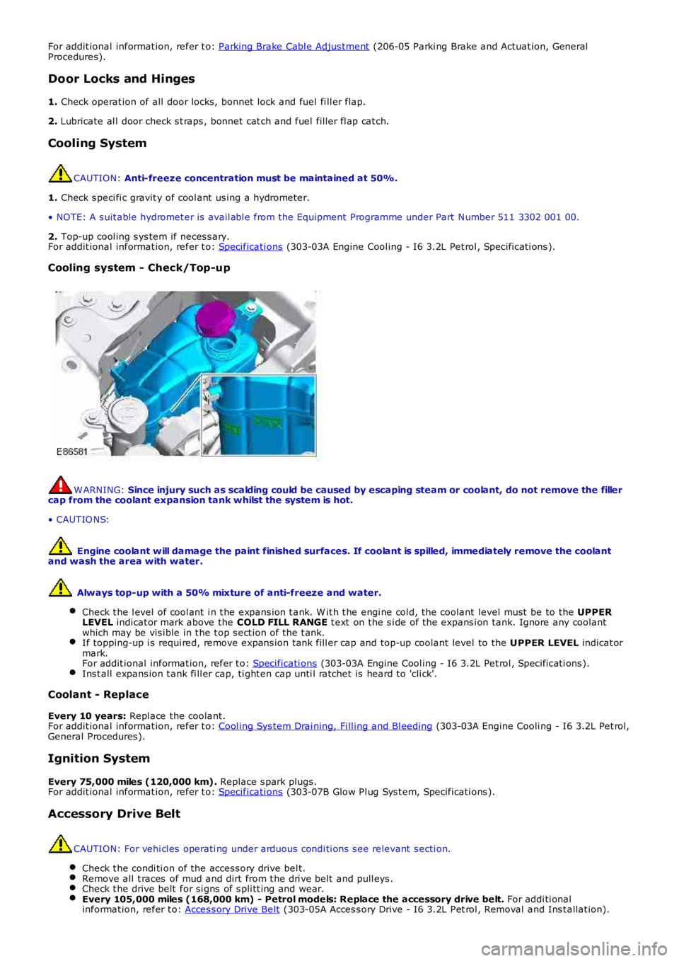
Cooling system - Check/Top-up
W ARNING: Since injury such as scalding could be caused by escaping steam or coolant, do not remove the fillercap from the coolant expansion tank whilst the system is hot.
• CAUTIO NS:
Engine coolant w ill damage the paint finished surfaces. If coolant is spilled, immediately remove the coolantand wash the area with water.
Always top-up with a 50% mixture of anti-freeze and water.
Check t he l evel of cool ant i n t he expans ion t ank. W it h t he engi ne col d, the coolant level must be to the UPPERLEVEL indicat or mark above the COLD FILL RANGE t ext on the s i de of the expans i on tank. Ignore any coolantwhich may be vis ible in t he t op s ect ion of t he t ank.If topping-up i s requi red, remove expans ion tank fill er cap and top-up coolant level to the UPPER LEVEL indicat ormark.For addit ional informat ion, refer t o: Specificati ons (303-03A Engine Cool ing - I6 3.2L Pet rol , Specificati ons ).Ins t all expans ion t ank fi ll er cap, ti ght en cap unti l ratchet is heard to 'cli ck'.
Coolant - Replace
Every 10 years: Repl ace the coolant.For addit ional informat ion, refer t o: Cool ing Sys tem Drai ning, Fi ll ing and Bl eeding (303-03A Engine Cooli ng - I6 3.2L Pet rol,General Procedures ).
Ignition System
Every 75,000 miles (120,000 km). Replace s park plugs .For addit ional informat ion, refer t o: Specificati ons (303-07B Glow Pl ug Sys t em, Specificati ons ).
Accessory Drive Belt
CAUTION: For vehi cl es operati ng under arduous condi ti ons s ee relevant s ecti on.
Check t he condi ti on of the access ory drive bel t.Remove all t races of mud and dirt from t he dri ve belt and pull eys .Check t he drive belt for si gns of s pli tt ing and wear.Every 105,000 miles (168,000 km) - Petrol models: Replace the accessory drive belt. For addi ti onalinformat ion, refer t o: Acces s ory Drive Belt (303-05A Acces s ory Drive - I6 3.2L Pet rol , Removal and Ins t allat ion).
Page 182 of 3229

Publi s hed: 11-May-2011
Maintenance Schedules - Maintenance Schedules - Diesel Engines
Des cript ion and Operat ion
Under Bonnet View Item
Part Number Description
1 -Coolant expans ion t ank
2 -Brake flui d res ervoir (RH drive i ll us t rat ed - LH dri ve on oppos i te si de)
3 -W indshi eld was her res ervoir
4 -Power s teeri ng fl uid reservoi r
5 -Engine oi l fil ler cap
6 -Engine oi l l evel i ndi cat or
Maintenance Operations CAUTION: Not e that t he A and B Services li st ed on t he Maint enance Check Sheet , appl i
cabl e t o vehi cl es operati ng
under arduous condi ti ons , vary bot h i n period and mil eage (kil ometres) t o t he int erv als s pecifi ed for t hose vehi cl es
operati ng under normal condit ions. Reference mus t therefore, always be made t o t he ' Arduous Condit ions s ect ion' for
vehi cl es operati ng under t hese condit ions .
Unles s s tat ed otherwis e, the foll owi ng operati ons mus t be carri ed out at every s ervi ce int erval.
Battery
Page 188 of 3229
For addit ional informat ion, refer t o: Parking Brake Cabl e Adjus tment (206-05 Parki ng Brake and Actuat ion, General
Procedures).
Door Locks and Hinges
1. Check operat ion of all door locks, bonnet lock and fuel fi ll er flap.
2. Lubricate al l door check s t raps , bonnet cat ch and fuel fill er fl ap cat ch.
Cooling System CAUTION:
Anti-freeze concentration must be maintained at 50%.
1. Check s peci fi c gravit y of cool ant us ing a hydrometer.
• NOTE: A s uit able hydromet er is avail abl e from the Equipment Programme under Part N umber 511 3302 001 00.
2. Top-up cool ing s ys tem if neces s ary.
For addit ional informat ion, refer t o: Specificati ons (303-03B Engine Cool ing - TD4 2.2L Dies el, Speci fi cat ions ).
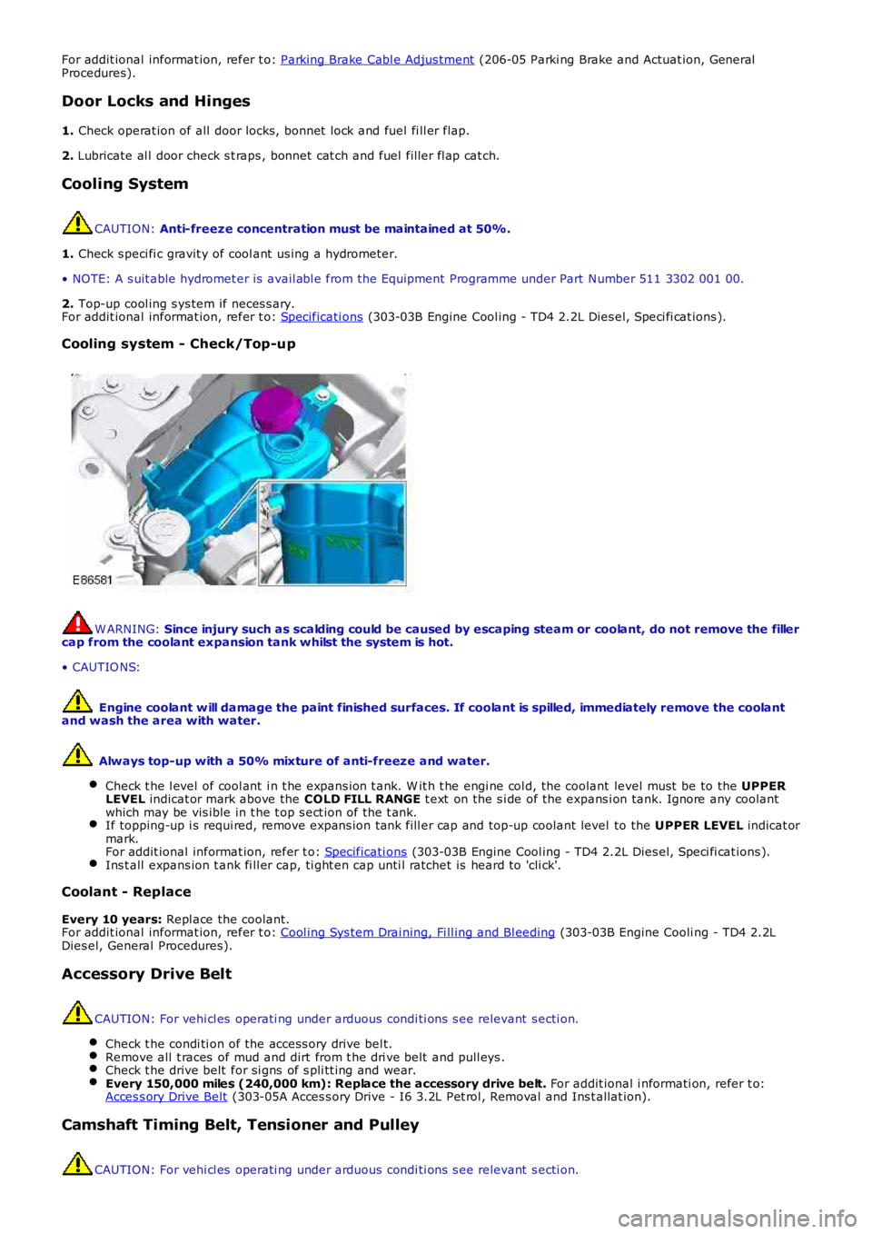
Cooling system - Check/Top-up W ARNING:
Since injury such as scalding could be caused by escaping steam or coolant, do not r emove the filler
cap from the coolant expansion tank whilst the system is hot.
• CAUTIO NS:
Engine coolant w ill damage the paint finished surfaces. If coolant is spilled, immed iately remove the coolant
and wash the area with water.
Always top-up with a 50% mixture of anti-freeze and water.
Check t he l evel of cool ant i n t he expans ion t ank. W it h t he engi ne col d, the coolant level must be to the UPPER
LEVEL indicat or mark above the COLD FILL RANGE t ext on the s i de of the expans i on tank. Ignore any coolant
which may be vis ible in t he t op s ect ion of t he t ank. If topping-up i s requi red, remove expans ion tank fill er cap and top-up coolant level
to the UPPER LEVEL indicat or
mark.
For addit ional informat ion, refer t o: Specificati ons (303-03B Engine Cool ing - TD4 2.2L Dies el, Speci fi cat ions ).
Ins t all expans ion t ank fi ll er cap, ti ght en cap unti l ratchet is heard to 'cli ck'.
Coolant - Replace
Every 10 years: Repl ace the coolant.
For addit ional informat ion, refer t o: Cool ing Sys tem Drai ning, Fi ll ing and Bl eeding (303-03B Engine Cooli ng - TD4 2.2L
Dies el, General Procedures).
Accessory Drive Belt CAUTION: For vehi cl es operati ng under arduous condi ti ons s ee relevant s ecti on.
Check t he condi ti on of the access ory drive bel t. Remove all t races of mud and dirt from t he dri ve belt and pull eys .
Check t he drive belt for si gns of s pli tt ing and wear.
Every 150,000 miles (240,000 km): Replace the accessory drive belt.
For addit ional i nformati on, refer t o:
Acces s ory Drive Belt (303-05A Acces s ory Drive - I6 3.2L Pet rol , Removal and Ins t allat ion).
Camshaft Timing Belt, Tensioner and Pulley
CAUTION: For vehi cl es operati ng under arduous condi ti ons s ee relevant s ecti on.
Page 607 of 3229

A Rear End Ancillary Drive (READ) s yst emTwo fabricated s t ainles s s t eel t win s kin exhaust manifoldsA 3-pos ition Variable Intake Sys t em (VIS)An advanced Engine Management Syst em (EMS) incorporat ing elect ronic t hrot tle controlFour cat alyt ic converters
Technical data
DESCR IPT IO NT YPEConfigurationInline 6-cylinderO utput171 kW at 6200 rpmT orque320 Nm at 3200 rpmDisplacement3192 cm³Stroke/bore96.0 mm/84.0 mmCompression ratio10.8:1Firing order1-5-3-6-2-4Approximate weight180 kg (including int ake pipe, exhaus t manifold, alt ernator and oil)
ItemPart NumberDescriptionA-Torque (Nm)B-Power (kW )
CYLINDER BLOCK COMPONENTS
The main cylinder block components are:
Cylinder blockConnect ing rods and pis tonsPist on cooling jet sGenerat orGear hous ingThermos tat hous ingCranks haft Pos it ion (CKP) s ensorKnock s ens orsCoolant pumpCoolant inlet pipe
Cylinder Numbering
The cylinders are numbered as shown below, wit h cylinder 1 at t he front of the engine.
Page 613 of 3229
The intermediat e s haft is us ed to locat e the cams haft drive s haft gear wheel in t he cylinder block. The shaft is journaled wit h adouble conical roller bearing. The auxiliary unit s haft drive gear wheel is in 2 pieces , wit h t he narrow half being s pring tensioned inthe opposit e direct ion t o t he wide half. This feat ure reduces nois e becaus e gear play is eliminat ed. Only t he wide half drives theauxiliary unit's gear wheel. The cams haft chain gear wheel is of t he conventional design.
The s haft is sealed against the exhaust side (i.e. the rear s ide of t he cylinder block) by a s ealing was her. To remove or inst all t hewasher, t he flywheel/flexplate must be removed.
Camshaft Drive O uter Shaft
The cams haft drive outer s haft is journaled at the front end of t he s haft with a double row bearing in t he gear hous ing. Needlebearings are us ed at t he rear end (pulley s ide) against t he auxiliary unit s haft . The camshaft drive out er s haft gear wheel is in 2pieces , a wide and a narrow half t o reduce nois e. The cams haft chain gear wheel is als o locat ed on the s haft and is us ed to drivethe cams hafts chain.
Auxiliary Unit Inner Shaft
The auxiliary unit inner s haft is journaled at t he front end of t he shaft (generator s ide) in t he gear housing with a s ingle rowbearing. Needle bearings are used at the rear end (pulley s ide) against the cams haft drive shaft . There is a pulley at t he rear endof the s haft that drives t he Air Condit ioning (AC) compress or and the power s t eering pump, via a polyvee belt . The shaft als odrives t he generat or at t he front end, via a sleeve connect or.
Thermostat Housing
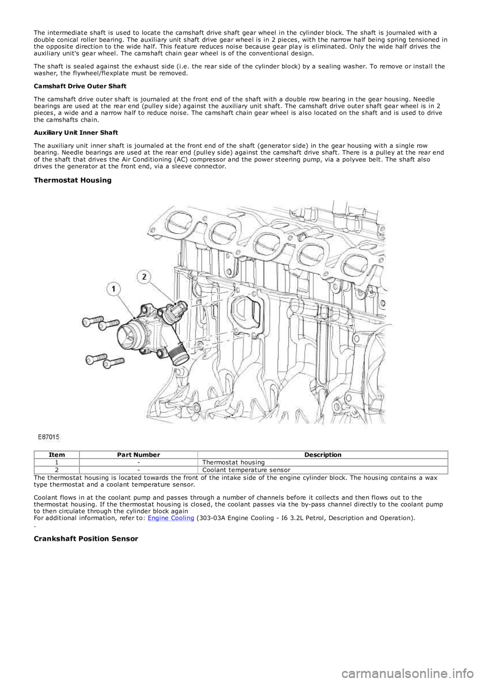
ItemPart NumberDescription1-Thermost at hous ing2-Coolant t emperat ure s ens orThe t hermos tat hous ing is located t owards the front of t he int ake s ide of t he engine cylinder block. The hous ing contains a waxtype t hermost at and a coolant temperat ure sens or.
Coolant flows in at t he coolant pump and pas s es through a number of channels before it collect s and t hen flows out t o t hethermos t at housing. If t he t hermost at hous ing is closed, t he coolant pass es via t he by-pass channel directly to t he coolant pumpto then circulat e t hrough t he cylinder block againFor addit ional information, refer t o: Engine Cooling (303-03A Engine Cooling - I6 3.2L Pet rol, Des cription and Operat ion)..
Crankshaft Position Sensor
Page 615 of 3229
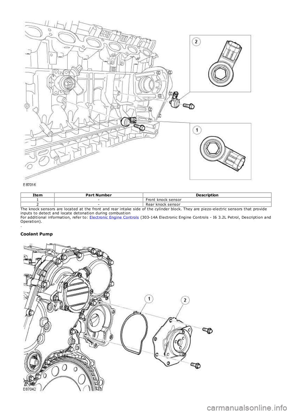
ItemPart NumberDescription1-Front knock s ens or2-Rear knock s ens orThe knock s ens ors are locat ed at t he front and rear int ake side of t he cylinder block. They are piezo-elect ric s ens ors t hat provideinput s t o detect and locate det onation during combust ionFor addit ional information, refer t o: Elect ronic Engine Cont rols (303-14A Elect ronic Engine Controls - I6 3.2L Pet rol, Des cript ion andOperation)..
Coolant Pump