2006 LAND ROVER FRELANDER 2 engine coolant
[x] Cancel search: engine coolantPage 762 of 3229
11-VGT oil return port
12-VGT oil s uppl y port
The cyl inder block is manufact ured from cas t -i ron and feat ures double layer wal ls t hat provide high st rengt h and ri gidit y.An air cus hion i s formed between t he l ayers and als o acts t o reduce t he NVH l evel s produced by the engine. The blockfeat ures 5 bol ted mai n beari ng journals that als o provi de high s t rength and rigi dit y to the l ower end of t he engine.
The cyl inders are direct ly bored int o t he cyl inder bl ock and do not require cyl inder liners. Two gui de s leeves are l ocated int he cyl inder bl ock, and provided t o correct ly al ign t he cyl inder head and gas ket to the cyli nder block.
A hole formed in the LH rear of the cyli nder bl ock below the st art er motor, provides the locat ion for an engine t imi ngs pecial t ool . W hen i nserted, the special tool locates i n a corres ponding hol e in the flywheel to temporaril y hol d t hecrankshaft wit h No. 1 pis t on at the Top Dead Cent er (TDC) posi ti on.
The oil filt er and cool er hous ing, and main oi l gal lery are locat ed on t he LH s ide of t he cylinder block. The mai n oil gall eryis a longit udinal dril li ng that runs t he l engt h of the cyli nder bl ock, and s uppl ies pres s urized oi l to al l the engine movi ngcomponents . Pres s uri zed oi l is di verted from t he main oi l gal lery to s upply the main and bi g-end bearings via diagonal oildri ll ings in the cyli nder block, and in t he crankshaft journals . The mai n oil gall ery i s s eal ed at each end wit h a s crewedplug.
A cros s dril ling above No. 2 mai n beari ng direct s pres surized oil from the main oi l gal lery to a port at t he Right-Hand (RH)s ide of t he cyl inder bl ock. The port s upplies press urized oil via a banjo t ype connect ion to t he VGT beari ngs. Ret urn oi lfrom the VGT is direct ed via a pipe and a connect ion at the RH si de of the bl ock, i nt o t he oil pan. A vert ical dril li ng at theLH front of the cyli nder bl ock s upplies press uri zed oil from the mai n oil gall ery, up t o a corresponding oi l gal lery in t hecyl inder head.
Engi ne cool ing i s achi eved wit h int er-cyl inder coolant chambers and expans ion chamber dril li ngs , formed i n t he cyl inderblock cool ant jacket . The coolant chambers direct coolant t hrough openings i n t he block upper s urface to the cyli nder head.Core pl ugs seal t he ext eri or openings formed i n t he cyl inder block coolant jacket.
Oil Spray Jets
Page 766 of 3229
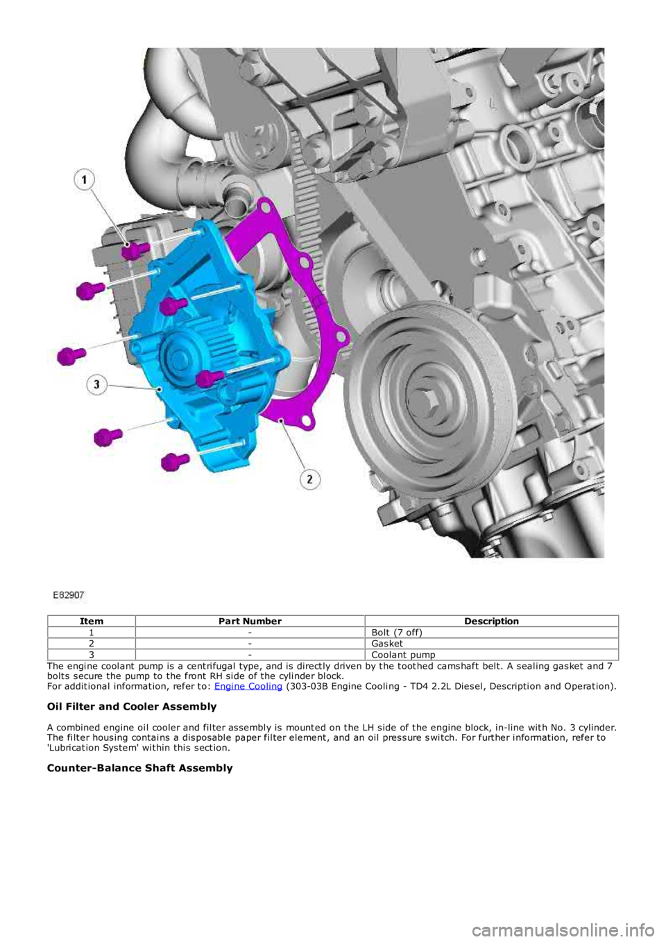
ItemPart NumberDescription
1-Bolt (7 off)2-Gas ket
3-Coolant pump
The engi ne cool ant pump is a cent ri fugal type, and is direct ly driven by t he t oot hed cams haft bel t. A s eal ing gas ket and 7bolt s s ecure the pump to the front RH si de of the cyli nder bl ock.For addit ional informat ion, refer t o: Engi ne Cooling (303-03B Engine Cooli ng - TD4 2.2L Dies el , Descripti on and Operat ion).
Oil Filter and Cooler Assembly
A combined engine oi l cooler and fil ter as sembl y is mount ed on t he LH s ide of t he engine block, in-line wit h No. 3 cylinder.The fi lt er hous ing contai ns a dis pos abl e paper fil ter element , and an oil pres s ure swi tch. For furt her i nformat ion, refer to'Lubri cat ion Sys tem' wi thin thi s s ect ion.
Counter-Balance Shaft Assembly
Page 796 of 3229
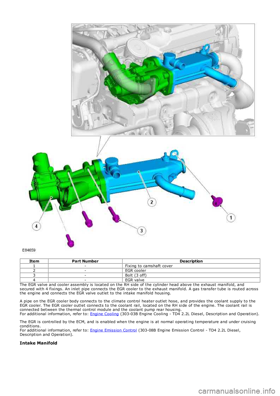
ItemPart NumberDescription
1-Fixi ng to cams haft cover2-EGR cooler
3-Bolt (3 off)
4-EGR valveThe EGR valve and cooler ass embl y is l ocat ed on t he RH s ide of t he cylinder head above t he exhaus t manifold, ands ecured wit h 4 fixi ngs . An i nl et pipe connects the EGR cooler t o t he exhaus t manifold. A gas t rans fer t ube is rout ed acros st he engi ne and connect s t he EGR valve out let t o the intake mani fold hous ing.
A pi pe on t he EGR cool er body connect s to the cl imat e cont rol heater outl et hos e, and provides t he cool ant s upply t o t heEGR cooler. The EGR cooler outl et connect s t o t he cool ant rail , locat ed on t he RH s ide of the engine. The cool ant rail isconnected bet ween the t hermal control modul e and the coolant pump rear hous ing.For addit ional informat ion, refer t o: Engi ne Cooling (303-03B Engine Cooli ng - TD4 2.2L Dies el , Descripti on and Operat ion).
The EGR i s cont rol led by t he ECM, and is enabled when t he engine i s at normal operati ng t emperature and under crui si ngcondi ti ons .For addit ional informat ion, refer t o: Engi ne Emis s ion Cont rol (303-08B Engi ne Emis s ion Cont rol - TD4 2.2L Di esel ,Des cript ion and Operat ion).
Intake Manifold
Page 801 of 3229
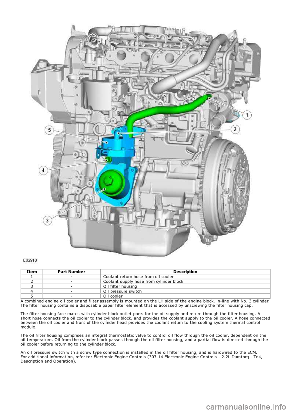
ItemPart NumberDescription
1-Cool ant return hose from oi l cooler2-Cool ant s upply hos e from cyl inder bl ock
3-Oil filt er hous i ng
4-Oil pres s ure s wi tch5-Oil cool er
A combined engine oi l cooler and fil ter as sembl y is mount ed on t he LH s ide of t he engine block, in-line wit h No. 3 cylinder.The fi lt er hous ing contai ns a dis pos abl e paper fil ter element t hat i s acces s ed by unscrewi ng t he fi lt er hous ing cap.
The fi lt er hous ing face mat es wit h cyl inder block out let ports for the oi l supply and return t hrough the fi lt er hous ing. As hort hose connect s t he oil cool er to the cyli nder block, and provides the coolant suppl y t o t he oil cool er. A hos e connectedbetween t he oil cooler and front of t he cylinder head provides t he coolant return to the cooli ng s ys t em t hermal cont rolmodule.
The oil filt er hous i ng compris es an i nt egral t hermos tat ic valve t o cont rol oi l flow through the oi l cooler, dependent on t heoil t emperature. Oil from the cyli nder block pass es t hrough t he oil fi lt er hous ing, and a parti al flow is di rected t hrough t heoil cool er before returning t o t he cyl inder bl ock.
An oil press ure swit ch wit h a s crew type connecti on is ins tall ed in the oi l fi lt er hous ing, and is hardwired to the ECM.For addit ional informat ion, refer t o: Electroni c Engi ne Controls (303-14 Electronic Engine Controls - 2.2L Durat orq - Td4,Des cript ion and Operat ion).
Page 802 of 3229
Publi s hed: 11-May-2011
Engine - TD4 2.2L Diesel - Engine
Diagnosi s and Tes ti ng
Principle of Operation
For a detail ed descripti on of the 2.2L Dies el engi ne, refer t o the relevant Descri pti on and Operat ion s ect ion in t heworks hop manual .REFER to: Engine (303-01B Engine - TD4 2.2L Dies el, Des cript ion and Operat ion).
Inspection and Verification
CAUTION: Di agnos is by s ubs ti tut ion from a donor vehicle is NO T acceptabl e. Subs ti tut ion of cont rol modules doesnot guarant ee confirmat ion of a faul t, and may als o caus e addit ional fault s i n t he vehi cl e being t est ed and/or t he donorvehi cl e.
• NOTE: If the control modul e or a component i s s us pect and the vehicle remains under manufacturer warrant y, refer t o theW arranty Pol icy and Procedures manual (s ect ion B1.2), or determine i f any pri or approval programme is in operat ion, pri ort o the ins tall ati on of a new module/component.
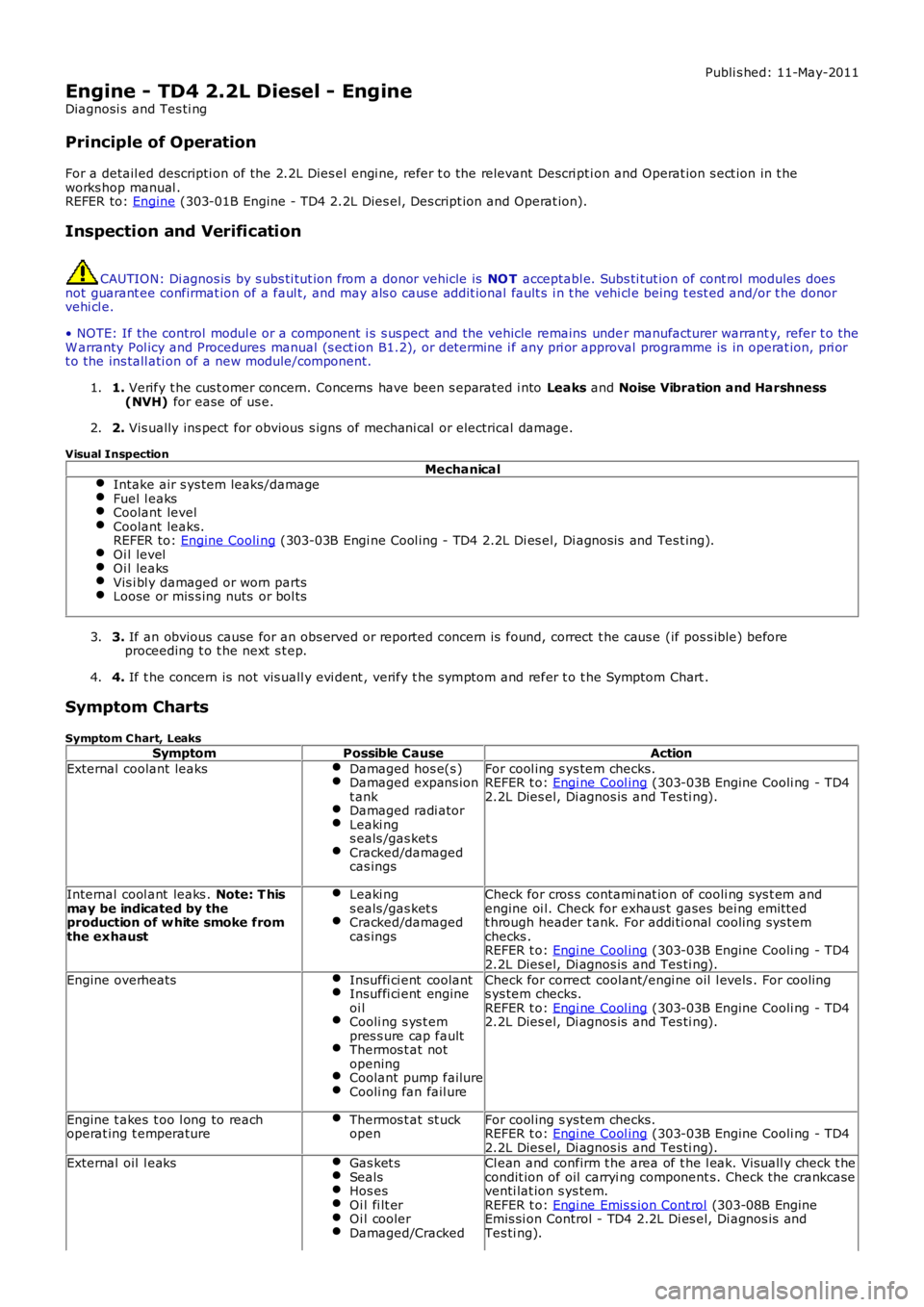
1. Verify t he cus t omer concern. Concerns have been s eparated i nto Leaks and Noise Vibration and Harshness(NVH) for ease of us e.1.
2. Vis ually ins pect for obvious s igns of mechani cal or electrical damage.2.
Visual Inspection
MechanicalIntake air s ys tem leaks/damageFuel l eaksCoolant levelCoolant leaks.REFER to: Engine Cooli ng (303-03B Engi ne Cool ing - TD4 2.2L Di es el, Di agnos is and Tes t ing).Oi l levelOi l leaksVis i bl y damaged or worn partsLoose or mis s ing nuts or bol ts
3. If an obvious cause for an obs erved or report ed concern is found, correct t he caus e (if pos s ible) beforeproceeding t o t he next s t ep.3.
4. If t he concern is not vis uall y evi dent , verify t he s ymptom and refer t o t he Symptom Chart .4.
Symptom Charts
Symptom C hart, LeaksSymptomPossible CauseAction
External coolant leaksDamaged hos e(s )Damaged expans iont ankDamaged radi atorLeaki ngs eals /gas ket sCracked/damagedcas ings
For cool ing s ys tem checks.REFER t o: Engi ne Cool ing (303-03B Engine Cooli ng - TD42.2L Dies el, Di agnos is and Tes ti ng).
Internal cool ant leaks . Note: T hismay be indicated by theproduction of w hite smoke fromthe exhaust
Leaki ngs eals /gas ket sCracked/damagedcas ings
Check for cros s contami nat ion of cooli ng sys t em andengine oi l. Check for exhaus t gases bei ng emit tedt hrough header t ank. For addi ti onal cooling sys temchecks .REFER t o: Engi ne Cool ing (303-03B Engine Cooli ng - TD42.2L Dies el, Di agnos is and Tes ti ng).
Engine overheatsInsuffi ci ent coolantInsuffi ci ent engineoi lCooli ng s ys t empres s ure cap faultThermos t at notopeningCoolant pump failureCooli ng fan fail ure
Check for correct coolant/engi ne oil l evels . For cool ings ys tem checks.REFER t o: Engi ne Cool ing (303-03B Engine Cooli ng - TD42.2L Dies el, Di agnos is and Tes ti ng).
Engine t akes t oo l ong to reachoperat ing t emperatureThermos t at st uckopenFor cool ing s ys tem checks.REFER t o: Engi ne Cool ing (303-03B Engine Cooli ng - TD42.2L Dies el, Di agnos is and Tes ti ng).External oil l eaksGas ket sSealsHos esOi l fi lt erOi l coolerDamaged/Cracked
Cl ean and confirm t he area of t he l eak. Vis uall y check t hecondit ion of oil carryi ng component s. Check the crankcaseventi lat ion s ys tem.REFER t o: Engi ne Emis s ion Cont rol (303-08B EngineEmis si on Control - TD4 2.2L Di es el, Di agnos is andTes ti ng).
Page 803 of 3229
SymptomPossible CauseAction
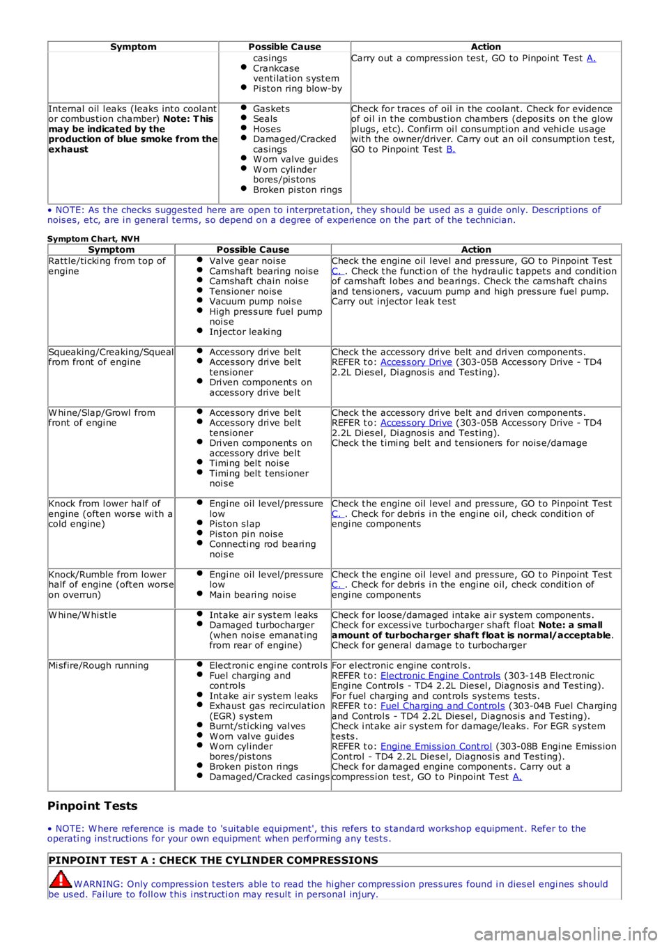
cas ingsCrankcaseventi lat ion s yst emPi st on ring blow-by
Carry out a compres s ion tes t, GO to Pinpoint Test A.
Internal oil l eaks (leaks int o cool antor combus t ion chamber) Note: T hismay be indicated by theproduction of blue smoke from theexhaust
Gas ket sSealsHos esDamaged/Crackedcas ingsW orn valve gui desW orn cyli nderbores /pi s tonsBroken pi st on rings
Check for t races of oil in the coolant. Check for evidenceof oi l i n t he combus t ion chambers (depos it s on t he glowpl ugs , et c). Confirm oi l cons umpti on and vehi cl e us agewit h the owner/driver. Carry out an oil consumpt ion t es t,GO t o Pinpoint Test B.
• NOTE: As t he checks s ugges ted here are open to i nterpretat ion, they s hould be us ed as a gui de only. Descripti ons ofnois es, et c, are i n general t erms, s o depend on a degree of experi ence on t he part of t he t echnician.
Symptom C hart, NVHSymptomPossible CauseAction
Ratt le/ti cki ng from t op ofengineVal ve gear noi seCamshaft bearing nois eCamshaft chain noi s eTens ioner nois eVacuum pump noi s eHigh pres s ure fuel pumpnoi s eInject or leaki ng
Check t he engi ne oil l evel and pres s ure, GO t o Pi npoint Tes tC. . Check t he functi on of the hydrauli c t appet s and condit ionof cams haft l obes and beari ngs. Check the cams haft chainsand tens ioners , vacuum pump and high pres s ure fuel pump.Carry out i njector l eak t es t
Squeaking/Creaking/Squealfrom front of engineAcces sory dri ve bel tAcces sory dri ve bel ttens ionerDri ven component s onaccess ory dri ve bel t
Check t he acces sory dri ve belt and dri ven components .REFER t o: Acces s ory Drive (303-05B Acces sory Drive - TD42.2L Di es el, Di agnos is and Tes t ing).
W hi ne/Slap/Growl fromfront of engi neAcces sory dri ve bel tAcces sory dri ve bel ttens ionerDri ven component s onaccess ory dri ve bel tTimi ng bel t nois eTimi ng bel t t ens ionernoi s e
Check t he acces sory dri ve belt and dri ven components .REFER t o: Acces s ory Drive (303-05B Acces sory Drive - TD42.2L Di es el, Di agnos is and Tes t ing).Check t he t imi ng bel t and t ens ioners for nois e/damage
Knock from l ower half ofengine (oft en wors e wi th acold engine)
Engi ne oil level/pres surelowPis ton s l apPis ton pi n nois eConnecti ng rod beari ngnoi s e
Check t he engi ne oil l evel and pres s ure, GO t o Pi npoint Tes tC. . Check for debri s i n the engi ne oil, check condit ion ofengi ne components
Knock/Rumble from lowerhalf of engine (oft en wors eon overrun)
Engi ne oil level/pres surelowMain beari ng nois e
Check t he engi ne oil l evel and pres s ure, GO t o Pi npoint Tes tC. . Check for debri s i n the engi ne oil, check condit ion ofengi ne components
W hi ne/W hi st leInt ake ai r s ys t em l eaksDamaged turbocharger(when nois e emanat ingfrom rear of engine)
Check for loose/damaged intake ai r sys tem components .Check for excess i ve turbocharger shaft fl oat Note: a smallamount of turbocharger shaft float is normal/acceptable.Check for general damage t o t urbocharger
Mi sfire/Rough runningElect roni c engi ne cont rol sFuel charging andcont rolsInt ake ai r s ys t em l eaksExhaus t gas recirculat ion(EGR) s yst emBurnt/s ti cki ng val vesW orn val ve guidesW orn cyl inderbores/pis t onsBroken pis ton ri ngsDamaged/Cracked cas ings
For el ect ronic engine controls .REFER t o: Electroni c Engine Controls (303-14B ElectronicEngi ne Cont rol s - TD4 2.2L Dies el , Diagnosi s and Test ing).For fuel charging and cont rols sys tems tes ts .REFER t o: Fuel Chargi ng and Cont rol s (303-04B Fuel Chargingand Cont rol s - TD4 2.2L Dies el , Diagnosi s and Test ing).Check i nt ake air s yst em for damage/leaks . For EGR s ys temtes ts .REFER t o: Engi ne Emi ss ion Cont rol (303-08B Engi ne Emis s ionCont rol - TD4 2.2L Dies el, Diagnos is and Tes ti ng).Check for damaged engine component s . Carry out acompress i on tes t, GO t o Pinpoint Test A.
Pinpoint Tests
• NOTE: W here reference is made to 's uit abl e equi pment', this refers t o s tandard workshop equipment . Refer to theoperati ng ins t ructi ons for your own equipment when performing any t es t s .
PINPOINT TEST A : CHECK THE CYLINDER COMPRESSIONS
W ARNING: Only compres s ion t es ters abl e t o read the hi gher compres si on pres s ures found i n dies el engi nes shouldbe us ed. Fai lure to foll ow t his i ns t ructi on may resul t in personal injury.
Page 908 of 3229
Publi s hed: 11-May-2011
Engine Cooling - I6 3.2L Petrol -
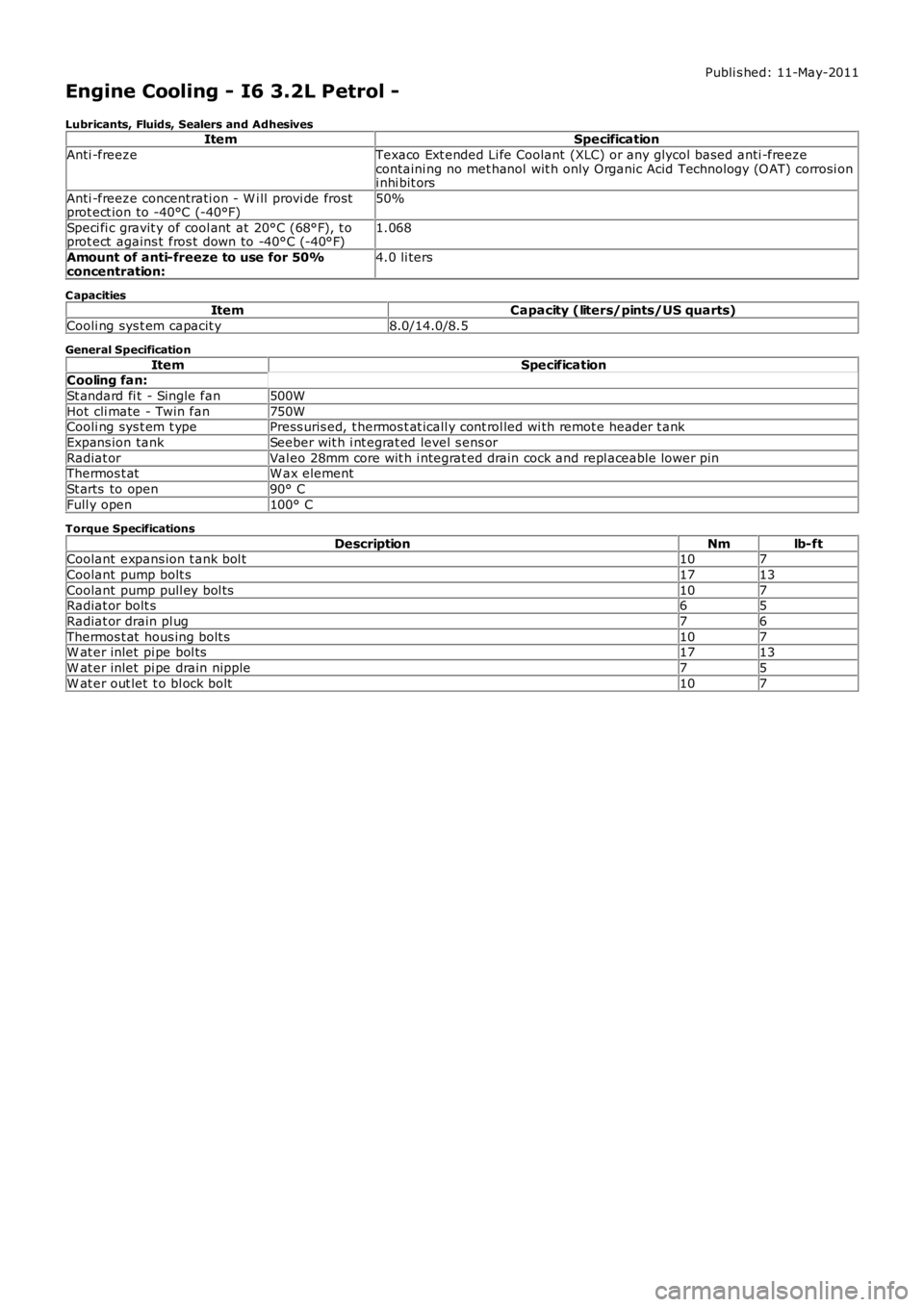
Lubricants, Fluids, Sealers and AdhesivesItemSpecification
Anti -freezeTexaco Ext ended Li fe Coolant (XLC) or any glycol bas ed anti -freezecontaini ng no met hanol wit h only Organic Acid Technology (O AT) corrosi oni nhi bit ors
Anti -freeze concentrati on - W i ll provi de frostprot ect ion to -40°C (-40°F)50%
Speci fi c gravit y of cool ant at 20°C (68°F), t oprot ect agains t fros t down to -40°C (-40°F)1.068
Amount of anti-freeze to use for 50%concentration:4.0 li ters
C apacitiesItemCapacity (liters/pints/US quarts)
Cooli ng sys t em capacit y8.0/14.0/8.5
General Specification
ItemSpecificationCooling fan:
St andard fi t - Single fan500W
Hot cli mate - Twin fan750WCooli ng sys t em t ypePress uris ed, t hermos t at icall y cont rol led wi th remot e header t ank
Expans ion tankSeeber wit h i nt egrat ed level s ens or
Radiat orVal eo 28mm core wit h i ntegrat ed drain cock and repl aceable lower pinThermos t atW ax element
St arts to open90° C
Full y open100° C
Torque Specifications
DescriptionNmlb-ftCoolant expans ion t ank bol t107
Coolant pump bolt s1713
Coolant pump pull ey bol ts107Radiat or bolt s65
Radiat or drain pl ug76
Thermos t at hous ing bolt s107W at er inlet pi pe bol ts1713
W at er inlet pi pe drain nipple75
W at er out let t o bl ock bolt107
Page 909 of 3229
Publi s hed: 11-May-2011
Engine Cooling - I6 3.2L Petrol - Engine Cooling
Des cript ion and Operat ion
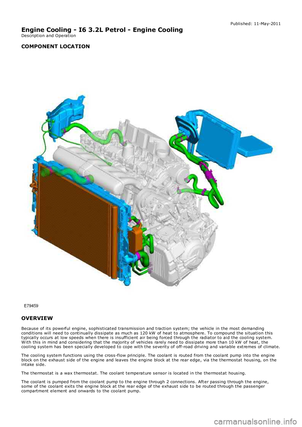
COMPONENT LOCATION
OVERVIEW
Becaus e of it s powerful engine, s ophi s ti cat ed transmis si on and t racti on s ys t em; the vehicle in the mos t demandingcondi ti ons will need t o cont inuall y dis s ipate as much as 120 kW of heat t o atmos phere. To compound the s i tuati on t hi st ypi call y occurs at low speeds when t here i s ins ufficient air being forced t hrough the radiat or t o ai d the cooli ng s ys t em.W i th thi s in mind and consi dering that t he majorit y of vehi cl es rarel y need to dis s ipate more t han 10 kW of heat , thecool ing s ys tem has been s peciall y devel oped t o cope wit h t he s everit y of off-road dri vi ng and variable ext remes of cl imat e.
The cool ing s ys tem functi ons us ing the cros s -flow pri ncipl e. The coolant is routed from t he cool ant pump int o the engi neblock on t he exhaus t s ide of t he engi ne and leaves the engine bl ock at t he rear edge, vi a t he t hermos tat housi ng, on theint ake si de.
The t hermos tat is a wax t hermos tat . The cool ant t emperat ure s ensor i s located i n t he thermost at hous i ng.
The cool ant i s pumped from the coolant pump t o t he engi ne through 2 connecti ons . After pass ing through t he engine,s ome of t he coolant exit s t he engi ne block at the rear edge of t he exhaus t s ide t o be routed t hrough t he pass engercompartment el ement and onwards to the coolant pump.