2006 LAND ROVER FRELANDER 2 fuse
[x] Cancel search: fusePage 1835 of 3229
NameItemNumberVehicleDescription
FuseF4038AllNot us ed
FuseF4137AllCJB fus es 1 t o 4
FuseF4230Manualt rans mis s ionECM
FuseF4230Automat ict rans mis s ionECM, TCM
FuseF4327AFSAFS control modul e
FuseF4327Headlamp l evel ingHeadlamp leveli ng cont rol module
FuseF4424AFSLH headl amp mot or
FuseF4523AllCi gar light er/access ory socket
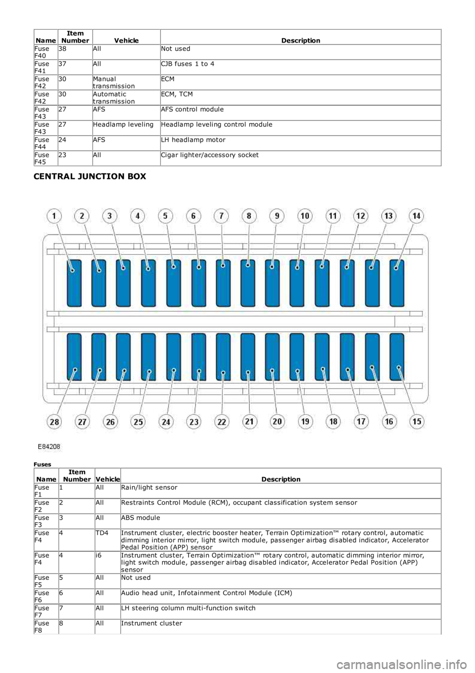
CENTRAL JUNCTION BOX
Fuses
NameItemNumberVehicleDescription
FuseF11AllRain/li ght s ens or
FuseF22AllRes traints Cont rol Module (RCM), occupant clas s ifi cat ion sys tem s ens or
FuseF33AllABS modul e
FuseF44TD4Inst rument clus t er, electric boos ter heat er, Terrain Opti mizati on™ rotary cont rol, aut omati cdimming interior mi rror, li ght swi tch modul e, pas s enger airbag di s abl ed indicator, Accelerat orPedal Pos it ion (APP) sens or
FuseF44i6Inst rument clus t er, Terrai n Opt imi zat ion™ rot ary control, automat ic di mming interior mi rror,l ight s wit ch modul e, pas s enger airbag dis abled i ndi cat or, Accel erator Pedal Pos it ion (APP)s ensorFuseF55AllNot us ed
FuseF66AllAudio head unit , Infotai nment Cont rol Modul e (ICM)
FuseF77AllLH s t eering column mult i-functi on s wit ch
FuseF88AllInst rument clus t er
Page 1836 of 3229
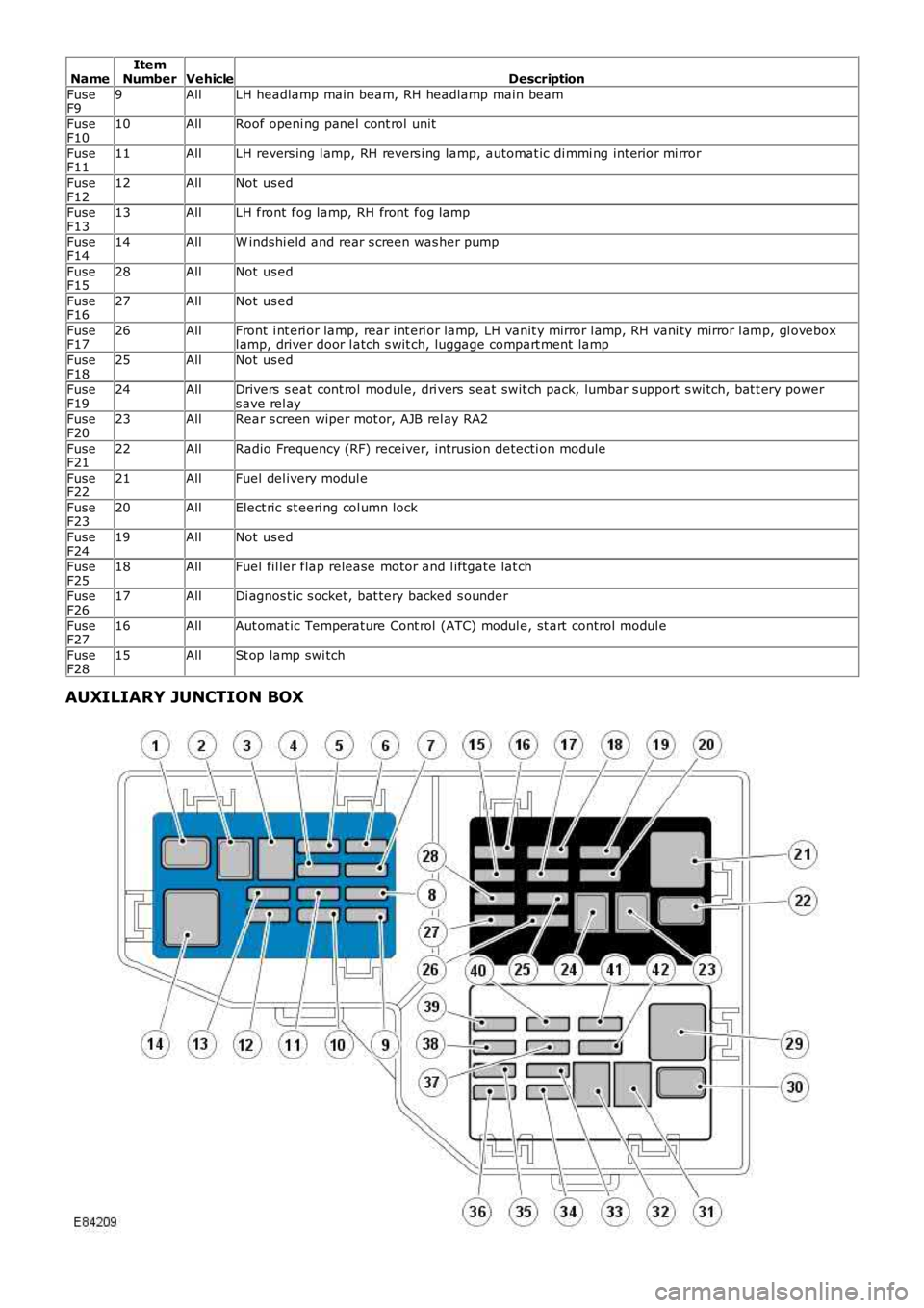
NameItemNumberVehicleDescription
FuseF99AllLH headlamp main beam, RH headlamp main beam
FuseF1010AllRoof openi ng panel cont rol unit
FuseF1111AllLH revers ing l amp, RH revers i ng lamp, automat ic di mmi ng int erior mi rror
FuseF1212AllNot us ed
FuseF1313AllLH front fog lamp, RH front fog lamp
FuseF1414AllW indshi eld and rear s creen was her pump
FuseF1528AllNot us ed
FuseF1627AllNot us ed
FuseF1726AllFront i nt eri or lamp, rear i nt eri or lamp, LH vanit y mirror l amp, RH vani ty mirror l amp, gl oveboxl amp, driver door l atch s wit ch, luggage compart ment lamp
FuseF1825AllNot us ed
FuseF1924AllDrivers s eat cont rol module, dri vers s eat swit ch pack, lumbar s upport s wi tch, bat t ery powers ave rel ayFuseF2023AllRear s creen wiper mot or, AJB rel ay RA2
FuseF2122AllRadio Frequency (RF) receiver, intrusi on detecti on module
FuseF2221AllFuel del ivery modul e
FuseF2320AllElect ric st eeri ng col umn lock
FuseF2419AllNot us ed
FuseF2518AllFuel fil ler flap release motor and l iftgate lat ch
FuseF2617AllDi agnos ti c s ocket, bat tery backed s ounder
FuseF2716AllAut omat ic Temperature Cont rol (ATC) modul e, st art control modul e
FuseF2815AllSt op lamp swi tch
AUXILIARY JUNCTION BOX
Page 1837 of 3229
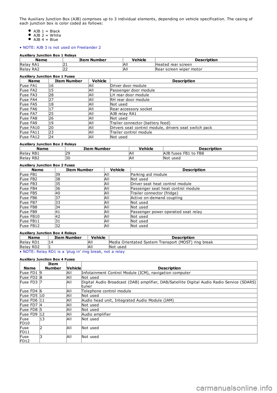
The Auxi li ary Junct ion Box (AJB) compris es up t o 3 i ndi vi dual el ement s , depending on vehicle specificati on. The casi ng ofeach junct ion box is color coded as foll ows:
AJB 1 = BlackAJB 2 = W hit eAJB 4 = Blue
• NOTE: AJB 3 i s not used on Freelander 2
Auxiliary Junction Box 1 Relays
NameItem NumberVehicleDescriptionRelay RA121AllHeat ed rear s creen
Relay RA222AllRear s creen wiper mot or
Auxiliary Junction Box 1 Fuses
NameItem NumberVehicleDescription
Fuse FA116AllDri ver door moduleFuse FA215AllPass enger door module
Fuse FA328AllLH rear door module
Fuse FA427AllRH rear door moduleFuse FA518AllNot used
Fuse FA617AllRear acces s ory socket
Fuse FA725AllAJB rel ay RA1Fuse FA826AllNot used
Fuse FA919AllTrail er connect or (bat tery feed)
Fuse FA1020AllDri vers s eat cont rol module, dri vers s eat s wi tch packFuse FA1123AllTrail er cont rol module
Fuse FA1224AllNot used
Auxiliary Junction Box 2 Relays
NameItem NumberVehicleDescriptionRelay RB129AllAJB fuses FB1 t o FB8
Relay RB230AllNot us ed
Auxiliary Junction Box 2 Fuses
NameItem NumberVehicleDescription
Fuse FB139Al lParki ng aid moduleFuse FB238Al lNot us ed
Fuse FB335Al lDriver seat heat cont rol module
Fuse FB436Al lPas senger seat heat cont rol moduleFuse FB540Al lTrai ler connector (fridge)
Fuse FB637Al lActi ve on-demand coupl ing
Fuse FB733Al lNot us edFuse FB834Al lNot us ed
Fuse FB941Al lPas senger power operat ed s eat relay
Fuse FB1042Al lNot us edFuse FB1131Al lNot us ed
Fuse FB1232Al lNot us ed
Auxiliary Junction Box 4 Relays
NameItem NumberVehicleDescriptionRelay RD114AllMedi a Orientat ed Syst em Transport (MOST) ring break
Relay RD21AllNot us ed
• NOTE: Relay RD1 is a 'plug i n' ring break, not a relay
Auxiliary Junction Box 4 Fuses
NameItemNumberVehicleDescriptionFuse FD19Al lInfotainment Control Modul e (ICM), navi gat ion computer
Fuse FD28Al lNot used
Fuse FD37Al lDigit al Audi o Broadcast (DAB) ampli fi er, DAB/Sat el li te Digit al Audi o Radi o Servi ce (SDARS)tuner
Fuse FD46Al lTel ephone control modul eFuse FD510Al lNot used
Fuse FD611Al lAudi o head unit , Int egrated Audio Modul e (IAM)
Fuse FD74Al lNot usedFuse FD85Al lNot used
Fuse FD912Al lAudi o ampli fi er
FuseFD1013Al lNot used
FuseFD112Al lNot used
FuseFD123Al lNot used
Page 1920 of 3229
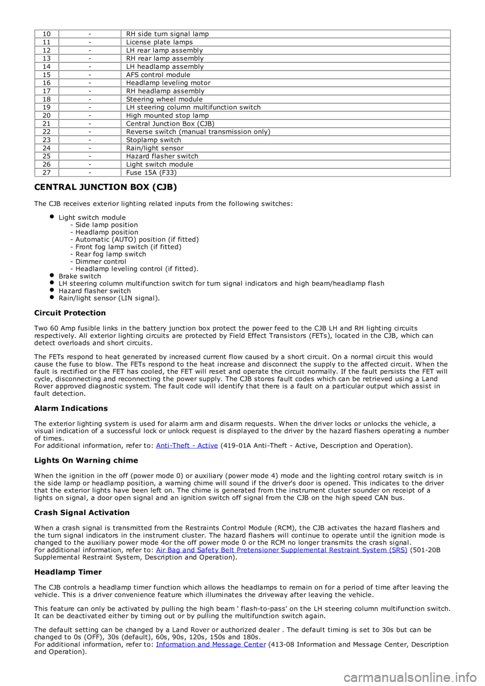
10-RH s i de turn s ignal lamp
11-Licens e pl ate lamps
12-LH rear l amp as s embl y13-RH rear lamp as s embly
14-LH headlamp as s embly
15-AFS cont rol module16-Headl amp l evel ing mot or
17-RH headlamp as s embly
18-Steering wheel modul e19-LH s t eering column mult ifunct ion s wit ch
20-High mount ed s top lamp
21-Central Junct ion Box (CJB)22-Revers e s wit ch (manual transmis si on only)
23-Stoplamp s wit ch
24-Rain/light s ensor25-Hazard flas her s wi tch
26-Light s wit ch modul e
27-Fuse 15A (F33)
CENTRAL JUNCTION BOX (CJB)
The CJB receives exteri or li ght ing relat ed inputs from t he fol lowing s wi tches:
Light s wit ch modul e- Side l amp pos it ion- Headlamp pos it ion- Automat ic (AUTO) posi ti on (if fi tt ed)- Front fog lamp swi tch (if fit ted)- Rear fog l amp s wit ch- Dimmer cont rol- Headlamp l evel ing control (if fit ted).Brake s wi tchLH s t eering column mult ifunct ion s wit ch for t urn si gnal i ndi cat ors and hi gh beam/headl amp flas hHazard flas her s wi tchRain/light s ensor (LIN si gnal ).
Circuit Protection
Two 60 Amp fus ibl e li nks in t he batt ery junct ion box protect the power feed to the CJB LH and RH li ght ing ci rcuit sres pect ively. All ext erior l ighti ng ci rcuit s are prot ect ed by Field Effect Trans is t ors (FETs ), l ocat ed in the CJB, which candetect overloads and s hort circuit s .
The FETs res pond to heat generated by increased current fl ow caus ed by a s hort ci rcuit . On a normal ci rcuit t his woul dcaus e t he fus e to bl ow. The FETs respond t o t he heat i ncrease and di s connect t he s uppl y t o t he affect ed ci rcuit . W hen t hefaul t is rect ified or t he FET has cool ed, t he FET wil l res et and operate t he circui t normall y. If t he faul t pers is ts the FET wi llcycle, di sconnect ing and reconnect ing t he power supply. The CJB s tores fault codes which can be ret rieved usi ng a LandRover approved diagnost ic sys tem. The fault code wil l identi fy t hat there is a fault on a part icular out put which as si s t infaul t det ect ion.
Alarm Indications
The exteri or li ght ing s ys tem is us ed for al arm arm and dis arm reques ts . W hen t he driver l ocks or unlocks the vehicle, avis ual i ndicat ion of a s uccess ful l ock or unlock reques t is di spl ayed t o t he dri ver by the hazard flas hers operat ing a numberof ti mes .For addit ional informat ion, refer t o: Anti -Theft - Act ive (419-01A Anti -Theft - Acti ve, Des cri pt ion and Operati on).
Lights On Warning chime
W hen t he i gni ti on in the off (power mode 0) or auxi liary (power mode 4) mode and the l ighti ng cont rol rotary swit ch is i nt he si de lamp or headlamp posi ti on, a warning chime wi ll s ound i f the driver's door is opened. This indicates t o t he dri vert hat t he exterior li ght s have been left on. The chime is generat ed from t he i ns t rument clus ter s ounder on receipt of ali ght s on s i gnal , a door open s ignal and an ignit ion swi tch off s ignal from t he CJB on the hi gh s peed CAN bus.
Crash Signal Activation
W hen a crash s ignal i s t rans mit ted from t he Rest rai nts Cont rol Modul e (RCM), t he CJB act ivat es the hazard flas hers andt he turn s ignal indicators in t he i ns t rument clus ter. The hazard fl ashers wil l continue to operate unt il t he ignit ion mode ischanged t o t he auxi liary power mode 4or the off power mode 0 or the RCM no longer trans mi ts the cras h si gnal .For addit ional informat ion, refer t o: Air Bag and Safet y Belt Pretens ioner Supplement al Res traint Syst em (SRS) (501-20BSuppl ement al Rest rai nt Sys tem, Des cri pti on and Operati on).
Headlamp Timer
The CJB cont rol s a headl amp t imer funct ion whi ch allows the headlamps t o remain on for a peri od of ti me after leaving t hevehi cl e. Thi s is a dri ver conveni ence feat ure which il lumi nat es t he dri veway after leaving t he vehicle.
This feat ure can onl y be acti vat ed by pulli ng t he high beam ' flas h-t o-pas s' on t he LH s t eering column mult ifunct ion s wi tch.It can be deacti vat ed eit her by ti ming out or by pull ing t he mul ti funct ion swi tch again.
The default s ett ing can be changed by a Land Rover or authorized deal er . The default t imi ng is s et t o 30s but can bechanged t o 0s (OFF), 30s (defaul t), 60s , 90s , 120s , 150s and 180s .For addit ional informat ion, refer t o: Informat ion and Mes s age Cent er (413-08 Informat ion and Mes s age Cent er, Des cript ionand Operat ion).
Page 1927 of 3229
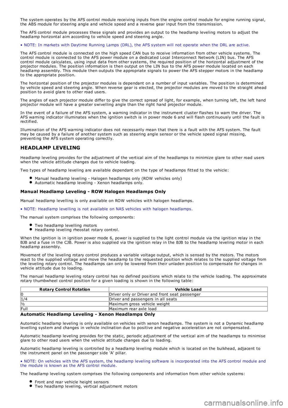
The s ys t em operat es by t he AFS cont rol module recei vi ng inputs from t he engine cont rol module for engine runni ng s ignal ,t he ABS module for st eeri ng angl e and vehi cle s peed and a reverse gear i nput from the trans mi ss i on.
The AFS cont rol module proces s es thes e s ignals and provi des an output t o the headlamp leveling motors to adjus t theheadl amp hori zont al ai m according t o vehicle speed and s teering angle.
• NOTE: In market s wit h Dayt ime Running Lamps (DRL), t he AFS s yst em will not operate when the DRL are act ive.
The AFS cont rol module is connect ed on the hi gh s peed CAN bus to receive i nformat ion from other vehicle s ys tems . Thecont rol module is connect ed to the AFS power module on a dedi cat ed Local Interconnect Net work (LIN) bus . The AFScont rol module cal culat es, us ing input dat a from other s ys t ems , the requi red pos it ion of t he hori zont al adjus t ment of t heproject or modul es. The pos it ion i nformat ion is t hen output on t he LIN bus to t he AFS power module l ocat ed on eachheadl amp as sembl y. Thi s module t hen outputs the appropriate s ignal s t o power the AFS s t epper mot ors i n t he headl ampt o the appropriat e posi ti on.
The hori zont al pos it ion of t he project or modul es is dependant on a number of input vari abl es . The pos it ion i s determinedby vehi cle s peed and s teeri ng angl e. W hen reverse gear i s elected, the projector modules are moved t o t he st rai ght aheadposi ti on t o avoi d glare t o other road us ers .
The angl es of each projector module di ffer to gi ve the correct spread of light , for example, when turning l eft , the l eft handproject or modul e wi ll have a great er s wi vel ling angl e than t he right hand projector module.
In the event of a fai lure of the AFS sys tem, a warning indicator in the ins trument cl us t er flas hes t o warn the driver. TheAFS warni ng indicator i lluminates when t he i gni ti on s wit ch is i n power mode 6 and will flas h cont inuousl y unti l the faul t isrect ifi ed.
Illumi nati on of the AFS warning i ndi cat or does not neces s aril y mean t hat there is a fault wit h the AFS sys tem. The faultmay be caus ed by a fai lure of anot her sys tem s uch as st eeri ng angl e s ens or or the vehicle s peed s i gnal mi ss i ng,preventi ng the AFS s ys tem operati ng correctl y.
HEADLAMP LEVELING
Headl amp l evel ing provides for the adjus t ment of the vert ical aim of the headlamps to minimi ze glare to other road us erswhen t he vehi cl e att it ude changes due t o vehi cle l oadi ng.
Two t ypes of headlamp l evel ing are avai lable dependant on the t ype of headlamps fit ted to the vehicle:
Manual headlamp l evel ing - Hal ogen headlamps only (ROW vehicles only)Automat ic headlamp level ing - Xenon headlamps only.
Manual Headlamp Leveling - ROW Halogen Headlamps Only
Manual headlamp l evel li ng is only avai lable on RO W vehicles wit h halogen headl amps .
• NOTE: Headlamp l evel ling is not avai lable on NAS vehicles wi th hal ogen headlamps .
The manual s ys tem compris es t he fol lowing components :
Two headlamp l evel ling motorsHeadl amp l evel ing rheos tat rotary cont rol .
W hen t he i gni ti on is i n i gni ti on power mode 6, power i s s uppli ed t o t he li ght control modul e via t he i gni ti on rel ay in t heBJB and a fuse in t he CJB. Power i s als o s uppl ied vi a the ignit ion relay i n the BJB to t he headlamp l evel ing mot or in eachheadl amp as sembl y.
Movement of t he leveli ng rot ary control produces a variable volt age output, whi ch is s ens ed by the motors. The mot orsreact to the suppli ed vol tage and move the headlamp t o t he reques ted pos it ion whi ch rel at es t o t he suppli ed volt age fromt he leveling rotary cont rol . The headlamps can onl y be lowered from t heir unladen posi ti on t o compens ate for changes invehi cl e at ti tude due t o l oading.
The manual headlamp level ing rotary cont rol has no defi ned pos i ti ons whi ch rel at e t o t he vehi cle l oadi ng. The approximat erot ary t humbwheel control pos it ion for a given l oadi ng is s hown i n t he fol lowing t able:
R otary Control RotationVehicle Load
0Driver only or Driver and front s eat pass enger1/4Driver and pass engers i n all s eats
½Maxi mum gross vehicle weight
FullMaxi mum rear axl e load
Automatic Headlamp Leveling - Xenon Headlamps Only
Automat ic headlamp level ing i s only avail abl e on vehicles wi th xenon headlamps . The sys tem is not a Dynami c headl amplevell ing s yst em and changes in vehicle inclinat ion due t o pos it ive and negat ive accelerat ion are not compens ated.
Automat ic headlamp level ing provi des for t he st ati c, periodic adjus t ment of the vertical aim of the headlamps t o mi nimi s eglare to other road us ers when the vehicle at t it ude changes due to loading.
Automat ic headlamp level ing i s cont rol led by a headlamp leveli ng modul e whi ch is l ocat ed on the bul khead, adjacent t ot he ins trument panel on t he pas s enger s ide 'A' pill ar.
• NOTE: On vehicles wit h the AFS sys tem, the headlamp l evel ing s oft ware is i ncorporated i nto the AFS control modul e andt he modul e i s known as the AFS control modul e.
The headl amp l eveli ng s ys t em compri s es the foll owing component s and informat ion from other vehi cl e s yst ems :
Front and rear vehicle height s ensorsTwo headlamp l evel ing, verti cal adjus t ment motors
Page 1933 of 3229
• NOTE: Generic scan t ool s may not read the codes li st ed, or may read only 5-digi t codes . Match t he 5 digi ts from t he s cant ool t o t he fi rs t 5 di gi ts of the 7-digit code li s ted t o i dent ify the fault (the last 2 digi ts gi ve ext ra informati on read by themanufacturer-approved di agnos ti c s ys t em).
• NOTE: Check and recti fy bas ic faul ts before beginni ng diagnos t ic rout ines i nvol vi ng pinpoint t es t s.
• NOTE: Ins pect connect ors for s igns of water ingres s , and pins for damage and/or corros ion.
• NOTE: If DTCs are recorded and, aft er performi ng the pi npoi nt tes ts , a fault is not present , an int ermi tt ent concern maybe t he caus e. Always check for loose connect ions and corroded terminals .
• NOTE: Pri or to ins tall ati on/replacement of the Headlamp Ass embly carry out all relevant i nternal vis ual and mechanicalchecks for correct cable l ocat ion and t erminati on including: checks for corroded, bent or backed out pi ns or terminals ,incorrect ly i nserted connect ors and harnes s damage due t o chaffi ng or incorrect routing.
• NOTE: If the control modul e has been removed and rei nst all ed, carry out a DTC code clear, cycl e t he ignit ion st ate to off,t hen on. This will erase any DTCs that have been l ogged during t he module ins tall ation procedure
For a compl ete lis t of all Di agnos ti c Trouble Codes (DTCs) t hat could be logged on this vehicle, pleas e refer to Sect ion100-00.
REFER to: Di agnos ti c Trouble Code (DTC) Index - DTC: Headlamp Cont rol Modul e (HCM) (100-00 General Informati on,Des cript ion and Operat ion).
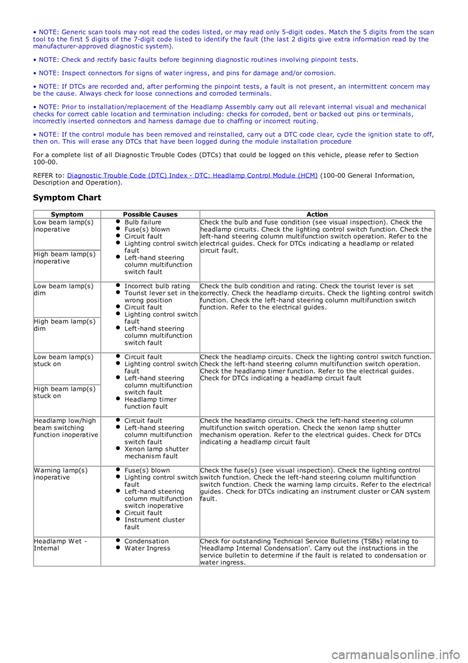
Symptom Chart
SymptomPossible CausesActionLow beam lamp(s )i noperat iveBulb fail ureFus e(s ) blownCi rcuit faul tLight ing control s wi tchfaul tLeft -hand s t eeringcolumn mult ifuncti ons wit ch faul t
Check t he bulb and fuse condit ion (s ee vis ual i nspecti on). Check theheadlamp ci rcuit s . Check t he li ght ing control swit ch funct ion. Check theleft -hand s t eering column mult ifunct ion s wi tch operat ion. Refer to theel ect ri cal guides . Check for DTCs indicati ng a headl amp or rel atedci rcuit faul t.Hi gh beam lamp(s )i noperat ive
Low beam lamp(s )dimIncorrect bul b rat ingTouri st l ever s et in thewrong pos i ti onCi rcuit faul tLight ing control s wi tchfaul tLeft -hand s t eeringcolumn mult ifuncti ons wit ch faul t
Check t he bulb condi ti on and rat ing. Check the t ouris t l ever i s s etcorrectl y. Check the headlamp ci rcuit s . Check t he li ght ing control swit chfunct ion. Check the l eft -hand s teering column mult ifuncti on s wit chfunct ion. Refer t o t he electrical gui des .
Hi gh beam lamp(s )dim
Low beam lamp(s )s tuck onCi rcuit faul tLight ing control s wi tchfaul tLeft -hand s t eeringcolumn mult ifuncti ons wit ch faul tHeadlamp ti merfunct ion faul t
Check t he headl amp circui ts . Check t he l ighti ng cont rol s wit ch functi on.Check t he left-hand st eeri ng col umn mul ti funct ion swi tch operat ion.Check t he headl amp t imer funct ion. Refer to the el ect ri cal guides .Check for DTCs i ndicat ing a headl amp circui t fault
Hi gh beam lamp(s )s tuck on
Headlamp l ow/hi ghbeam s wi tchingfunct ion i noperat ive
Ci rcuit faul tLeft -hand s t eeringcolumn mult ifuncti ons wit ch faul tXenon lamp s hut termechani s m fault
Check t he headl amp circui ts . Check t he l eft-hand s teeri ng col umnmult ifunct ion s wit ch operati on. Check t he xenon l amp s hutt ermechanis m operati on. Refer t o t he electrical gui des . Check for DTCsindicati ng a headl amp circui t fault
W arning l amp(s )i noperat iveFus e(s ) blownLight ing control s wi tchfaul tLeft -hand s t eeringcolumn mult ifuncti ons wit ch inoperat iveCi rcuit faul tInst rument clus t erfaul t
Check t he fus e(s ) (s ee vi s ual i ns pecti on). Check t he li ghti ng cont rolswi tch funct ion. Check t he l eft -hand s teeri ng column mul ti functi onswi tch funct ion. Check t he warni ng lamp circuit s . Refer to the el ect ri calgui des . Check for DTCs indicat ing an i nst rument clus ter or CAN s ys temfault .
Headlamp W et -InternalCondens ati onW at er Ingres sCheck for out st anding Techni cal Service Bull eti ns (TSBs ) rel at ing to'Headl amp Internal Condens ati on'. Carry out the i nst ruct ions in theservi ce bullet in to det ermi ne if t he faul t is relat ed to condens at ion orwater ingres s .
Page 1949 of 3229
Publi s hed: 11-May-2011
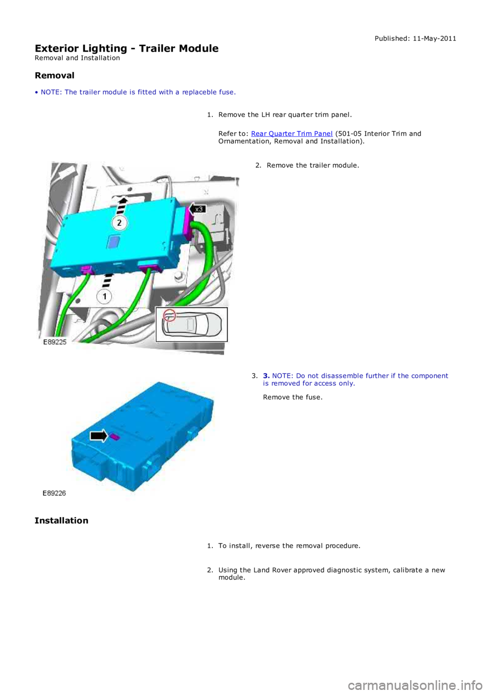
Exterior Lighting - Trailer Module
Removal and Inst all ati on
Removal
• NOTE: The t rail er modul e i s fi tt ed wi th a replaceble fuse.
Remove t he LH rear quart er trim panel .
Refer t o: Rear Quarter Tri m Panel (501-05 Int erior Tri m andOrnament ati on, Removal and Ins tal lat ion).
1.
Remove the trai ler module.2.
3. NOTE: Do not dis ass embl e further if t he componenti s removed for acces s onl y.
Remove t he fus e.
3.
Installation
To i nst all , revers e t he removal procedure.1.
Us ing t he Land Rover approved diagnost ic sys tem, cali brat e a newmodule.2.
Page 1960 of 3229
Publi s hed: 11-May-2011
Daytime Running Lamps (DRL) - Daytime Running Lamps (DRL)
Diagnosi s and Tes ti ng
Principles of Operation
For a detail ed descripti on of the dayt ime running l amps sys t em, refer t o t he rel evant Des cript ion and Operat ion s ecti on int he works hop manual .REFER to: Dayti me Running Lamps (DRL) (417-04 Dayt ime Running Lamps (DRL), Des cri pt ion and Operati on).
Inspection and Verification
1. Verify t he cus t omer concern.1.
2. Vis ually ins pect for obvious s igns of damage and s ys t em i ntegri ty.2.
Visual Inspection
Electrical
Fuses (refer to the el ect ri cal guide)BulbsSwit chesElectrical connect orsW iri ng harnes s
3. If an obvious cause for an obs erved or report ed concern is found, correct t he caus e (if pos s ible) beforeproceeding t o t he next s t ep.3.
4. If t he caus e is not vis ually evi dent , check for Di agnos ti c Trouble Codes (DTCs) and refer t o t he relevantDi agnos ti c s ect ion and DTC Index.4.