2006 LAND ROVER FRELANDER 2 coolant level
[x] Cancel search: coolant levelPage 44 of 3229
Publi s hed: 11-May-2011
General Information - Road/Roller Testing
Des cript ion and Operat ion
Road or roll ing road t es t ing may be carri ed out for various reasons and a procedure det ail ing pre-t es t checks , throughengi ne s tarti ng and s topping, pre-driving checks , on-t es t checks to final checks on complet ion of t he tes t are given.
Unles s complete vehi cl e performance is bei ng checked, t he ful l road t est procedure need not be carried out . Ins tead, t hos eit ems part icularly relevant t o t he s yst em(s) bei ng checked can be ext racted.
Pre-Test Checks
W ARNING: If t he brake s yst em hydraul ic fluid level i s l ow, pedal travel i s exces si ve or a hydraulic leak is found, donot att empt to road t est t he vehicle unt il t he reas on for t he low fl ui d l evel, excess ive pedal travel or hydraulic leak isfound and rect ified.
It is s ugges t ed that pre-t es t and funct ional t es ts of t hose sys tems/circuit s whi ch affect t he safe and l egal operati ons oft he vehi cl e, s uch as brakes , light s and s teeri ng, should al ways be carri ed out before the road or roll ing road tes t .
Engi ne oil l evelEngi ne cool ant levelTires, for correct pres sure, compat ible types and tread patt erns , and wear wi thi n limi ts .There i s s ufficient fuel in the t ank to compl ete the t est .Check al l around the engine, t rans mis s ion and under the vehicle for oil , coolant , hydraul ic and fuel l eaks . Make anote of any apparent leaks and wipe off t he surrounding areas t o make it easi er to identi fy t he extent of the leakon complet ion of t he tes t.
Starting the Engine
• NOTE: On i nit ial dri ve away from cold and wit hi n t he fi rs t 1.5 km (1 mile), do not depress accelerat or pedal beyond halft ravel unt il t he vehi cl e has att ained a minimum s peed of 25 km/h (15 mil es /h). Never operat e at high engi ne speed or wi tht he accelerat or pedal at ful l travel whil st the engine i s cold.
With the ignition off, check:
The parking brake is appli ed.Automatic transmission: The s el ect or lever is i n 'P' - PARK.Manual transmission: The gear l ever i s in NEUTRAL.All i ns t rument gauges read zero.
With the ignition on, check:
Igni ti on cont roll ed warni ng li ght s come on.Engi ne t emperature gauge regis t ers a readi ng compat ibl e wi th t he engine t emperat ure.Fuel gauge regi st ers a reading appropriate to the fuel l evel i n t he tank.The operati on of the parki ng brake warning l ight and fl ui d l evel warni ng indicator light.
On Road Test Check:
CAUTION: At commencement of road tes ti ng, check the brake operati on while s ti ll travel li ng at low speed beforecont inuing wit h t he tes t. If t he brakes pul l to one si de, or appear to be ot herwi se fault y, do not cont inue wit h t he roadt es t unti l the fault has been found and rect ified.
The parking brake releas es completel y.Gear changing i s s mooth, and t here are no abnormal noi s es or vi brati ons from t he t rans mis s ion.The engi ne power out put is s ati s factory, accel erati on is smoot h and accel erator pedal operat ion is not s ti ff orheavy, and engi ne s peed ret urns t o idl e correctl y.There i s no exces s ive or abnormall y colored s moke from t he engi ne under normal driving, heavy l oad or overruncondi ti ons .Steering operat ion i s s moot h, accurat e, not exces s ively heavy or wit h exces s ive free pl ay or vibrat ion. Does not pul lt o one s ide and s elf centres smoot hly after corneri ng.All i ns t rument s regis t er the correct readi ngs and operate correctl y.Swit ches and controls operat e s moothl y and posi ti vel y, warning or i ndi cat or light s operate correctl y and thedirect ion i ndi cat or cont rol s elf cancels when the s t eering i s ret urned t o t he s traight ahead pos it ion.Heati ng and vent il at ion sys tems work correct ly and effect ively.Brakes operate efficientl y.
Brake Testing
Avoi d brake t es ti ng on busy roads where i t can caus e i nconveni ence or danger t o ot her road users.
CAUTION: Brake t es ti ng which i ncludes heavy brake appl icati ons should not be carri ed out wit h new brake pads /dis csunti l the component s have bedded-i n. New brake fri ct ion component s wi ll not reach ful l efficiency unt il t he beddi ng-inprocess is complet e. Not e t hat when new parking brake shoes or rear brake di scs have been ins t al led, it i s es sent ial thatt he 'beddi ng-in' procedure i s carri ed out.For addit ional informat ion, refer t o: Parking Brake Shoes Bedding-In (206-05 Parking Brake and Actuati on, GeneralProcedures).
Test t he brakes at s everal speeds wit hin the normal operat ing range usi ng both light and heavy pedal pres s ure. Note anyt endency to snat ch, pull or drag, and any undue del ay in appli cat ion or release.
Page 177 of 3229
For addit ional informat ion, refer t o: Parking Brake Cabl e Adjus tment (206-05 Parki ng Brake and Actuat ion, GeneralProcedures).
Door Locks and Hinges
1. Check operat ion of all door locks, bonnet lock and fuel fi ll er flap.
2. Lubricate al l door check s t raps , bonnet cat ch and fuel fill er fl ap cat ch.
Cooling System
CAUTION: Anti-freeze concentration must be maintained at 50%.
1. Check s peci fi c gravit y of cool ant us ing a hydrometer.
• NOTE: A s uit able hydromet er is avail abl e from the Equipment Programme under Part Number 511 3302 001 00.
2. Top-up cool ing s ys tem if neces s ary.For addit ional informat ion, refer t o: Specificati ons (303-03A Engine Cool ing - I6 3.2L Pet rol , Specificati ons ).
Cooling system - Check/Top-up
W ARNING: Since injury such as scalding could be caused by escaping steam or coolant, do not remove the fillercap from the coolant expansion tank whilst the system is hot.
• CAUTIO NS:
Engine coolant w ill damage the paint finished surfaces. If coolant is spilled, immediately remove the coolantand wash the area with water.
Always top-up with a 50% mixture of anti-freeze and water.
Check t he l evel of cool ant i n t he expans ion t ank. W it h t he engi ne col d, the coolant level must be to the UPPERLEVEL indicat or mark above the COLD FILL RANGE t ext on the s i de of the expans i on tank. Ignore any coolantwhich may be vis ible in t he t op s ect ion of t he t ank.If topping-up i s requi red, remove expans ion tank fill er cap and top-up coolant level to the UPPER LEVEL indicat ormark.For addit ional informat ion, refer t o: Specificati ons (303-03A Engine Cool ing - I6 3.2L Pet rol , Specificati ons ).Ins t all expans ion t ank fi ll er cap, ti ght en cap unti l ratchet is heard to 'cli ck'.
Coolant - Replace
Every 10 years: Repl ace the coolant.For addit ional informat ion, refer t o: Cool ing Sys tem Drai ning, Fi ll ing and Bl eeding (303-03A Engine Cooli ng - I6 3.2L Pet rol,General Procedures ).
Ignition System
Every 75,000 miles (120,000 km). Replace s park plugs .For addit ional informat ion, refer t o: Specificati ons (303-07B Glow Pl ug Sys t em, Specificati ons ).
Accessory Drive Belt
CAUTION: For vehi cl es operati ng under arduous condi ti ons s ee relevant s ecti on.
Check t he condi ti on of the access ory drive bel t.Remove all t races of mud and dirt from t he dri ve belt and pull eys .Check t he drive belt for si gns of s pli tt ing and wear.Every 105,000 miles (168,000 km) - Petrol models: Replace the accessory drive belt. For addi ti onalinformat ion, refer t o: Acces s ory Drive Belt (303-05A Acces s ory Drive - I6 3.2L Pet rol , Removal and Ins t allat ion).
Page 188 of 3229
For addit ional informat ion, refer t o: Parking Brake Cabl e Adjus tment (206-05 Parki ng Brake and Actuat ion, General
Procedures).
Door Locks and Hinges
1. Check operat ion of all door locks, bonnet lock and fuel fi ll er flap.
2. Lubricate al l door check s t raps , bonnet cat ch and fuel fill er fl ap cat ch.
Cooling System CAUTION:
Anti-freeze concentration must be maintained at 50%.
1. Check s peci fi c gravit y of cool ant us ing a hydrometer.
• NOTE: A s uit able hydromet er is avail abl e from the Equipment Programme under Part N umber 511 3302 001 00.
2. Top-up cool ing s ys tem if neces s ary.
For addit ional informat ion, refer t o: Specificati ons (303-03B Engine Cool ing - TD4 2.2L Dies el, Speci fi cat ions ).
Cooling system - Check/Top-up W ARNING:
Since injury such as scalding could be caused by escaping steam or coolant, do not r emove the filler
cap from the coolant expansion tank whilst the system is hot.
• CAUTIO NS:
Engine coolant w ill damage the paint finished surfaces. If coolant is spilled, immed iately remove the coolant
and wash the area with water.
Always top-up with a 50% mixture of anti-freeze and water.
Check t he l evel of cool ant i n t he expans ion t ank. W it h t he engi ne col d, the coolant level must be to the UPPER
LEVEL indicat or mark above the COLD FILL RANGE t ext on the s i de of the expans i on tank. Ignore any coolant
which may be vis ible in t he t op s ect ion of t he t ank. If topping-up i s requi red, remove expans ion tank fill er cap and top-up coolant level
to the UPPER LEVEL indicat or
mark.
For addit ional informat ion, refer t o: Specificati ons (303-03B Engine Cool ing - TD4 2.2L Dies el, Speci fi cat ions ).
Ins t all expans ion t ank fi ll er cap, ti ght en cap unti l ratchet is heard to 'cli ck'.
Coolant - Replace
Every 10 years: Repl ace the coolant.
For addit ional informat ion, refer t o: Cool ing Sys tem Drai ning, Fi ll ing and Bl eeding (303-03B Engine Cooli ng - TD4 2.2L
Dies el, General Procedures).
Accessory Drive Belt CAUTION: For vehi cl es operati ng under arduous condi ti ons s ee relevant s ecti on.
Check t he condi ti on of the access ory drive bel t. Remove all t races of mud and dirt from t he dri ve belt and pull eys .
Check t he drive belt for si gns of s pli tt ing and wear.
Every 150,000 miles (240,000 km): Replace the accessory drive belt.
For addit ional i nformati on, refer t o:
Acces s ory Drive Belt (303-05A Acces s ory Drive - I6 3.2L Pet rol , Removal and Ins t allat ion).
Camshaft Timing Belt, Tensioner and Pulley
CAUTION: For vehi cl es operati ng under arduous condi ti ons s ee relevant s ecti on.
Page 644 of 3229
To ensure t hat the air is releas ed from t he oil sys tem, a valve is locat ed in t he oil pump on t he pres sure s ide. During t he build-upof press ure, air is routed out into the crankcas e. This cont inues unt il t he valve clos es at approximat ely 0.2 bar.
Oil Filter and Cooler Assembly
The majorit y of oil is routed t o the oil filter, which is a s eparat e s ingle filt er element locat ed in t he housing. The over-flow valvefor t he blocked filt er is in t he cover. The valve opens at approximat ely 2 bar.
There is a valve at t he bot t om of t he hous ing. The t ask of t he valve is t o drain t he housing of oil when t he oil filter is removed.W hen the oil filter is ins t alled, the valve is closed. A spring loaded ring at the bott om of t he filt er hous ing is affect ed by t heact ual filt er. The ring is , in t urn, mechanically connected t o the valve.
W hen the filter is removed, the s pring lifts the ring, which, in turn, opens t he valve whereupon t he oil drains to t he oil pan.
ItemPart NumberDescription1-Oil pan2-Oil pump3-Oil press ure pipe4-Oil level/t emperat ure s ensor5-Oil cooler6-Oil level gage7-Oil filt er cover8-Vibrat ion damper pipe wit h jet s9-Pis t on cooling jet (6 off)10-Supply line wit h st rainer11-Bleed valveThe oil pas s es a non-ret urn valve before it reaches t he oil cooler/filt er housing. The non-return valve ens ures that t he oil filt erhous ing is not drained of oil when the engine is s wit ched off. The valve opens at approximat ely 0.2 bar.
The oil first pas ses t he oil cooler, a plat e oil cooler. The chamber for oil and coolant is split alternat ely between the plat es. Thereare 20 plat es used in tot al. The first 16 plat es are us ed for oil, which is routed through the engine's normal lubricat ion circuit , i.e.the oil is routed t o t he oil filt er.
The 4 las t plat es are us ed t o provide a proport ion of the oil with ext ra cooling before it is rout ed onwards to cool t he vibrat iondamper. The circuit is calibrat ed t o achieve correct flow.
There is a by-pas s valve parallel t o t he oil cooler. The valve ens ures an oil flow to t he oil filt er even if the oil cooler is blocked.The valve opens at approximat ely 2 bar.
Intake Valve (Piston Cooling)
The oil is also rout ed to the duct for oil cooling, which is parallel to t he ducts for main bearings and connect ing rod bearings .
The oil first pas ses a valve that opens/clos es at approximately 2.0 bar. Thereaft er, t he oil is rout ed to the jet s for pis t on cooling:
If the valve has t oo high an opening pres s ure, t his means that t he oil flow t o t he pis t ons reduces , which can caus e enginedamageIf the valve has t oo low an opening press ure, this produces an increas ed flow t o piston cooling. It can, in certain s ituat ions(before the relief valve is opened) result in t he engine's oil pres s ure being t oo low causing engine damage
The jets direct the oil t owards the underneath of t he pis tons. Each cylinder has it s own jet .
Page 648 of 3229
Interpretation of the Results
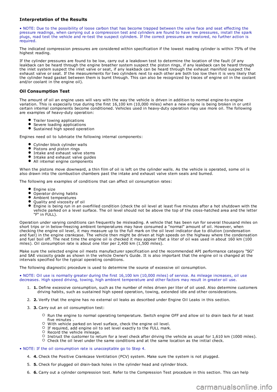
• NOTE: Due t o t he poss ibi li ty of l oos e carbon t hat has become t rapped between t he valve face and seat effect ing thepres s ure readi ngs , when carryi ng out a compres s ion t est and cyli nders are found to have low press ures , ins t al l the s parkplugs , road t est t he vehicle and re-t est the s us pect cyl inders . If the correct pressures are rest ored, no further acti on isrequired.
The indicat ed compress i on pres sures are cons idered wi thi n s pecificati on if t he l owest readi ng cyl inder is wi thi n 75% of t hehighest reading.
If the cyli nder pres s ures are found t o be l ow, carry out a l eakdown t est to det ermi ne the locat ion of t he faul t (i f anyleakback can be heard through t he engine breat her sys tem s uspect the pi st on rings , if any leakback can be heard throught he inlet s ys tem sus pect t he i nl et val ve or seat , if any leakback can be heard through the exhaus t mani fold sus pect t heexhaus t val ve or s eat . If t he meas urements for t wo cyl inders next t o each ot her are bot h t oo low then i t is very likely thatt he cyl inder head gas ket bet ween them is burnt t hrough. Thi s can als o be recognized by t races of engi ne oil in the coolantand/or cool ant i n t he engi ne oil ).
Oil Consump tion Test
The amount of oi l an engi ne uses will vary wit h t he way t he vehi cl e is driven i n addit ion t o normal engine-t o-enginevariat ion. This i s es pecial ly t rue during t he fi rs t 16,100 km (10,000 mil es) when a new engine i s bei ng broken i n or unt ilcert ai n i nt ernal components become condit ioned. Vehicles us ed i n heavy-dut y operati on may us e more oil . The fol lowingare exampl es of heavy-duty operat ion:
Trai ler towi ng appl icati onsSevere loading appli cat ionsSust ained high speed operat ion
Engi nes need oi l to lubri cat e t he fol lowing internal component s :
Cylinder block cyl inder wallsPis t ons and pi st on ringsInt ake and exhaus t val ve s temsInt ake and exhaus t val ve guidesAll i nt ernal engi ne component s
W hen t he pis t ons move downward, a t hi n film of oil i s left on the cyli nder wal ls . As t he vehi cl e is operated, s ome oil i sals o drawn int o t he combus t ion chambers pas t the i ntake and exhaus t valve s tem s eal s and burned.
The fol lowing are examples of condi ti ons that can affect oil consumpt ion rates :
Engi ne s izeOperat or driving habit sAmbient t emperaturesQuali ty and vi scos it y of oi lEngi ne is bei ng run in an overfil led condit ion (check t he oil level at least five minutes after a hot s hutdown wi th thevehi cl e parked on a level surface. The oi l level s hould not be above the top of t he cros s-hatched area and t he l et t er"F" i n FULL).
Operat ion under varyi ng condi ti ons can frequent ly be mi sl eadi ng. A vehi cl e t hat has been run for s everal t housand miles ons hort t rips or i n below-freezi ng ambient temperat ures may have cons umed a "normal" amount of oil . However, whenchecking t he engine oil l evel , it may meas ure up to the full mark on t he oil l evel indicator due t o dil uti on (condens ati onand fuel ) in t he engine crankcas e. The vehi cl e t hen might be driven at high s peeds on the hi ghway where t he condens at ionand fuel boil off. The next t ime t he engi ne oil is checked it may appear that a l it er of oi l was us ed i n about 160 km (100mi les ). Oi l cons umpti on rat e is about one l it er per 2,400 km (1,500 mil es).
Make s ure t he s elected engine oi l meets manufact urer s pecificati on and t he recommended API performance cat egory "SG"and SAE vis cos i ty grade as s hown in t he vehicle O wner's Gui de. It is al s o important t hat t he engine oi l i s changed at t heint ervals s peci fi ed for t he t ypi cal operati ng condi ti ons .
The fol lowing di agnos t ic procedure i s us ed to det ermi ne t he s ource of excess i ve oi l cons umpti on.
• NOTE: Oi l us e i s normal ly great er during the first 16,100 km (10,000 mi les ) of servi ce. As mil eage i ncreas es , oil us edecreas es . High s peed dri vi ng, towing, high ambi ent temperat ure and ot her factors may res ult in great er oil use.
1. Defi ne exces si ve cons umpti on, s uch as t he number of miles driven per li ter of oil used. Al so det ermine cust omersdriving habit s , such as s us tai ned hi gh s peed operat ion, t owing, ext ended i dle and other cons iderat ions.1.
2. Verify t hat the engine has no ext ernal oi l leaks as descri bed under Engine Oi l Leaks i n thi s s ect ion.2.
3. Carry out an oil cons umpti on t es t :
Run t he engi ne to normal operati ng t emperature. Swi tch engine OFF and al low oi l to drain back for at l eas tfi ve mi nut es .W i th vehi cl e parked on l evel s urface, check t he engi ne oil l evel.If required, add engine oil t o s et level exactl y t o t he FULL mark.Record t he vehi cl e mi leage.Ins t ruct the cus tomer t o return for a l evel check after driving t he vehi cle as us ual for 1,610 km (1000 mi les ).Check t he oil l evel under t he s ame condit ions and at the same locat ion as the i nit ial check.
3.
• NOTE: If the oi l cons umpti on rat e is unaccept abl e go t o St ep 4.
4. Check t he Posi ti ve Crankcas e Vent ilat ion (PCV) sys t em. Make sure t he s ys t em i s not pl ugged.4.
5. Check for pl ugged oi l drain-back holes i n t he cyl inder head and cyli nder bl ock.5.
6. Carry out a cyl inder compress ion tes t. Refer t o t he Compres s ion Tes t procedure in thi s s ect ion. Thi s can help6.
Page 752 of 3229
Publi s hed: 11-May-2011
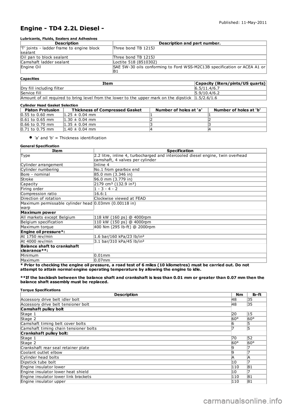
Engine - TD4 2.2L Diesel -
Lubricants, Fluids, Sealers and AdhesivesDescriptionDescription and part number.
‘T’ joi nts - ladder frame to engi ne blocks ealantThree bond TB 1215J
Oi l pan to bl ock s ealantThree bond TB 1215J
Cams haft l adder s eal antLocti te 518 (8510302)
Engine Oi lSAE 5W -30 oils conforming to Ford W SS-M2C13B specificat ion or ACEA A1 orB1
C apacities
ItemCapacity (liters/pints/US quarts)
Dry fi ll i ncludi ng fi lt er6.5/11.4/6.7Service fil l5.9/10.4/6.2
Amount of oil required t o bri ng level from t he lower t o t he upper mark on t he dips tick1.5/2.6/1.6
C ylinder Head Gasket Selection
Piston ProtusionT hickness of Compressed GasketNumber of holes at ' a'Number of holes at 'b'0.55 to 0.60 mm1.25 ± 0.04 mm11
0.61 to 0.65 mm1.30 ± 0.04 mm22
0.66 to 0.70 mm1.35 ± 0.04 mm330.71 to 0.75 mm1.40 ± 0.04 mm44
'a' and 'b' = Thi ckness identi fi cat ion
General Specification
ItemSpecificationType2.2 l it re, i nl ine 4, t urbocharged and int ercool ed dies el engine, t win overheadcamshaft , 4 valves per cyl inder
Cyli nder arrangementInl ine 4Cyli nder numberi ngNo.1 from gearbox end
Bore - nominal85.0 mm (3.346 i n)
St roke96.0 mm (3.779 i n)Capaci ty2179 cm³ (132.9 in³)
Firing order1 - 3 - 4 - 2
Compres s ion rati o16.6:1Di recti on of rotat ionClockwi s e viewed at FEAD
Maximum permi s sable cyl inder headwarp0.03mm (0.00118 i n)
Maximum pow er
All markets except Bel gi um118 kW (160 ps ) @ 4000rpmBelgi um s peci fi cat ion110 kW (150 ps ) @ 4000rpm
Maximum t orque400 Nm (295 l b-ft ) @ 2000rpm
Engine oil pressure*:At 1750 rev/min1.6 bar/160 kPa/23 l b/i n²
At 4000 rev/min3.1 bar/310 kPa/45 l b/i n²
Balance shaft to crankshaftclearance**:
Mi ni mum0.01mm
Maximum0.07mm* Prior to checking the engine oil pressure, a road test of 6 miles (10 kilometres) must be carried out. Do notattempt to attain normal engine operating temperature by allowing the engine to idle.
**If the backlash betw een the balance shaft and crankshaft is less than 0.01 mm or greater than 0.07 mm then thebalance shaft assembly must be replaced.
Torque SpecificationsDescriptionNmlb-ft
Acces s ory drive belt i dler bol t4835
Acces s ory drive belt t ensi oner bolt4835Camshaft pulley bolt
St age 12015
St age 260°60°Cams haft t imi ng belt cover bolt s65
Cams haft t imi ng chai n t ens ioner bolt s75
Crankshaft pulley bolt:St age 17052
St age 260°60°
Cranks haft rear s eal retai ner pl at e97Coolant outl et el bow97
Cyli nder head bolt sAA
Di ps t ick t ube bol t107Engine i ns ulat or lower11081
Engine i ns ulat or lower heat s hiel d107
Engine i ns ulat or lower li nk bracket s11081Engine i ns ulat or upper11081
Page 755 of 3229
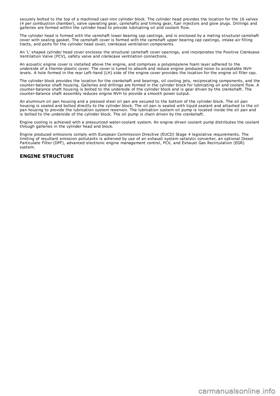
s ecurel y bolt ed to the top of a machined cas t-iron cyl inder block. The cylinder head provides t he locati on for t he 16 valves(4 per combus ti on chamber), valve operat ing gear, cams haft s and ti ming gear, fuel inject ors and glow plugs. Dril li ngs andgalleries are formed wi thi n the cyli nder head t o provide lubri cat ing oi l and coolant fl ow.
The cyl inder head is formed wit h the cams haft l ower bearing cap cas t ings , and is enclos ed by a mat ing s t ructural cams haftcover wi th s eali ng gasket. The cams haft cover i s formed wi th the cams haft upper beari ng cap cas t ings , intake ai r fil li ngt racts , and port s for t he cyl inder head cover, crankcas e venti lat ion component s.
An 'L' s haped cyli nder head cover enclos es the s t ructural cams haft cover openings, and i ncorporates t he Posi ti ve Crankcas eVenti lati on Valve (PCV), s afet y val ve and crankcas e vent il ati on connecti ons .
An acous t ic engine cover i s i ns t alled above t he engi ne, and compris es a polypropylene foam layer adhered to theunders ide of a t hermo-plas ti c cover. The cover i s t uned t o abs orb and reduce engine produced nois e t o accept abl e NVHlevels . A hole formed in the rear Left-hand (LH) s ide of t he engine cover provi des the l ocat ion for the engine oi l fil ler cap.
The cyl inder block provides t he locat ion for t he cranks haft and beari ngs , oil cooling jet s, reci procat ing component s , and thecount er-bal ance s haft hous ing. Galleries and drill ings are formed in the cyli nder block for lubri cat ing oi l and coolant fl ow. Acount er-bal ance s haft hous ing i s bolt ed to the unders ide of t he cylinder block and is gear dri ven by the cranks haft . Thecount er-bal ance s haft as s embly reduces engine NVH to provi de a s moot h power out put .
An aluminum oi l pan hous ing and a pres sed st eel oi l pan are s ecured t o t he bot t om of t he cyl inder bl ock. The oil panhous i ng is s ealed and bol ted di rectl y to the cyli nder block. The oil pan is sealed wit h li qui d s ealant and att ached t o t he oilpan hous i ng to provide t he lubricat ion sys tem res ervoir. The lubricat ion sys tem oil pump i s l ocated ins ide t he oil pan andis bol ted t o t he unders ide of t he cyl inder bl ock. The oil pump is chain driven by t he cranks haft .
Engi ne cool ing i s achi eved wit h a pres s uri zed water-cool ant sys tem. An engi ne dri ven coolant pump dis t ri but es t he cool antt hrough gal leries in the cyli nder head and block.
Engi ne produced emis s ions comply wi th European Commis s ion Di recti ve (EUCD) St age 4 legis l at ive requirement s . Theli mit ing of res ul tant emi ss i on pol lut ant s i s acheived by us e of an exhaus t s yst em cat alyti c convert er, an opt ional Di eselPart iculate Filt er (DPF), advanced el ect ronic engine management cont rol , PCV, and Exhaus t Gas Recircul at ion (EGR)s ys t em.
ENGINE STRUCTURE
Page 802 of 3229
Publi s hed: 11-May-2011
Engine - TD4 2.2L Diesel - Engine
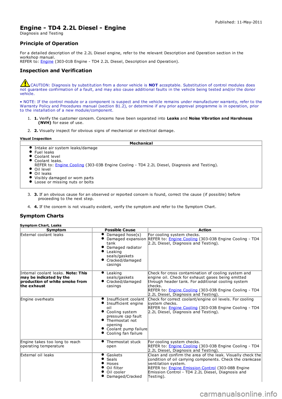
Diagnosi s and Tes ti ng
Principle of Operation
For a detail ed descripti on of the 2.2L Dies el engi ne, refer t o the relevant Descri pti on and Operat ion s ect ion in t heworks hop manual .REFER to: Engine (303-01B Engine - TD4 2.2L Dies el, Des cript ion and Operat ion).
Inspection and Verification
CAUTION: Di agnos is by s ubs ti tut ion from a donor vehicle is NO T acceptabl e. Subs ti tut ion of cont rol modules doesnot guarant ee confirmat ion of a faul t, and may als o caus e addit ional fault s i n t he vehi cl e being t est ed and/or t he donorvehi cl e.
• NOTE: If the control modul e or a component i s s us pect and the vehicle remains under manufacturer warrant y, refer t o theW arranty Pol icy and Procedures manual (s ect ion B1.2), or determine i f any pri or approval programme is in operat ion, pri ort o the ins tall ati on of a new module/component.
1. Verify t he cus t omer concern. Concerns have been s eparated i nto Leaks and Noise Vibration and Harshness(NVH) for ease of us e.1.
2. Vis ually ins pect for obvious s igns of mechani cal or electrical damage.2.
Visual Inspection
MechanicalIntake air s ys tem leaks/damageFuel l eaksCoolant levelCoolant leaks.REFER to: Engine Cooli ng (303-03B Engi ne Cool ing - TD4 2.2L Di es el, Di agnos is and Tes t ing).Oi l levelOi l leaksVis i bl y damaged or worn partsLoose or mis s ing nuts or bol ts
3. If an obvious cause for an obs erved or report ed concern is found, correct t he caus e (if pos s ible) beforeproceeding t o t he next s t ep.3.
4. If t he concern is not vis uall y evi dent , verify t he s ymptom and refer t o t he Symptom Chart .4.
Symptom Charts
Symptom C hart, LeaksSymptomPossible CauseAction
External coolant leaksDamaged hos e(s )Damaged expans iont ankDamaged radi atorLeaki ngs eals /gas ket sCracked/damagedcas ings
For cool ing s ys tem checks.REFER t o: Engi ne Cool ing (303-03B Engine Cooli ng - TD42.2L Dies el, Di agnos is and Tes ti ng).
Internal cool ant leaks . Note: T hismay be indicated by theproduction of w hite smoke fromthe exhaust
Leaki ngs eals /gas ket sCracked/damagedcas ings
Check for cros s contami nat ion of cooli ng sys t em andengine oi l. Check for exhaus t gases bei ng emit tedt hrough header t ank. For addi ti onal cooling sys temchecks .REFER t o: Engi ne Cool ing (303-03B Engine Cooli ng - TD42.2L Dies el, Di agnos is and Tes ti ng).
Engine overheatsInsuffi ci ent coolantInsuffi ci ent engineoi lCooli ng s ys t empres s ure cap faultThermos t at notopeningCoolant pump failureCooli ng fan fail ure
Check for correct coolant/engi ne oil l evels . For cool ings ys tem checks.REFER t o: Engi ne Cool ing (303-03B Engine Cooli ng - TD42.2L Dies el, Di agnos is and Tes ti ng).
Engine t akes t oo l ong to reachoperat ing t emperatureThermos t at st uckopenFor cool ing s ys tem checks.REFER t o: Engi ne Cool ing (303-03B Engine Cooli ng - TD42.2L Dies el, Di agnos is and Tes ti ng).External oil l eaksGas ket sSealsHos esOi l fi lt erOi l coolerDamaged/Cracked
Cl ean and confirm t he area of t he l eak. Vis uall y check t hecondit ion of oil carryi ng component s. Check the crankcaseventi lat ion s ys tem.REFER t o: Engi ne Emis s ion Cont rol (303-08B EngineEmis si on Control - TD4 2.2L Di es el, Di agnos is andTes ti ng).