2006 LAND ROVER FRELANDER 2 rear entertainment
[x] Cancel search: rear entertainmentPage 1904 of 3229
Publi s hed: 11-May-2011
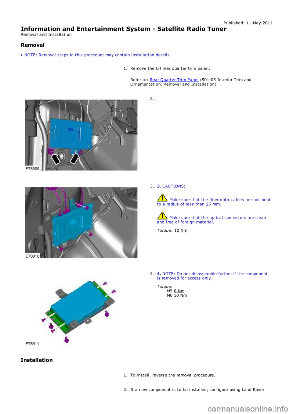
Information and Entertainment System - Satellite Radio Tuner
Removal and Inst all ati on
Removal
• NOTE: Removal s t eps in t his procedure may cont ain i nst all ati on det ail s.
Remove t he LH rear quart er trim panel .
Refer t o: Rear Quarter Tri m Panel (501-05 Int erior Tri m and
Ornament ati on, Removal and Ins tal lat ion).
1. 2.
3.
CAUTIONS: Make s ure that t he fi ber opt ic cables are not bent
t o a radius of les s t han 25 mm. Make s ure that t he opti cal connectors are cl ean
and free of foreign mat eri al.
T orque: 10 Nm 3.
4.
NOTE: Do not dis ass embl e further if t he component
i s removed for acces s onl y.
T orque: M5 6 Nm M6
10 Nm 4.
Installation To i nst all , revers e t he removal procedure.
1.
If a new component i s t o be ins t al led, configure usi ng Land Rover
2.
Page 1905 of 3229
Publi s hed: 11-May-2011
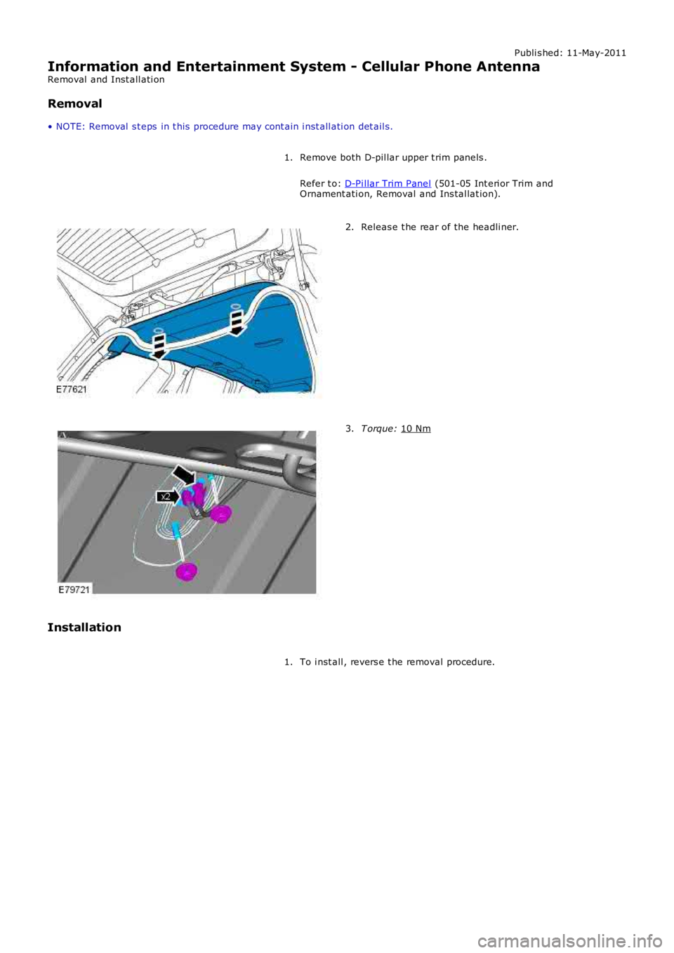
Information and Entertainment System - Cellular Phone Antenna
Removal and Inst all ati on
Removal
• NOTE: Removal s t eps in t his procedure may cont ain i nst all ati on det ail s.
Remove both D-pil lar upper t rim panels .
Refer t o: D-Pi llar Trim Panel (501-05 Int eri or Trim and
Ornament ati on, Removal and Ins tal lat ion).
1. Releas e t he rear of the headli ner.
2. T orque:
10 Nm 3.
Installation To i nst all , revers e t he removal procedure.
1.
Page 1907 of 3229
Publi s hed: 11-May-2011
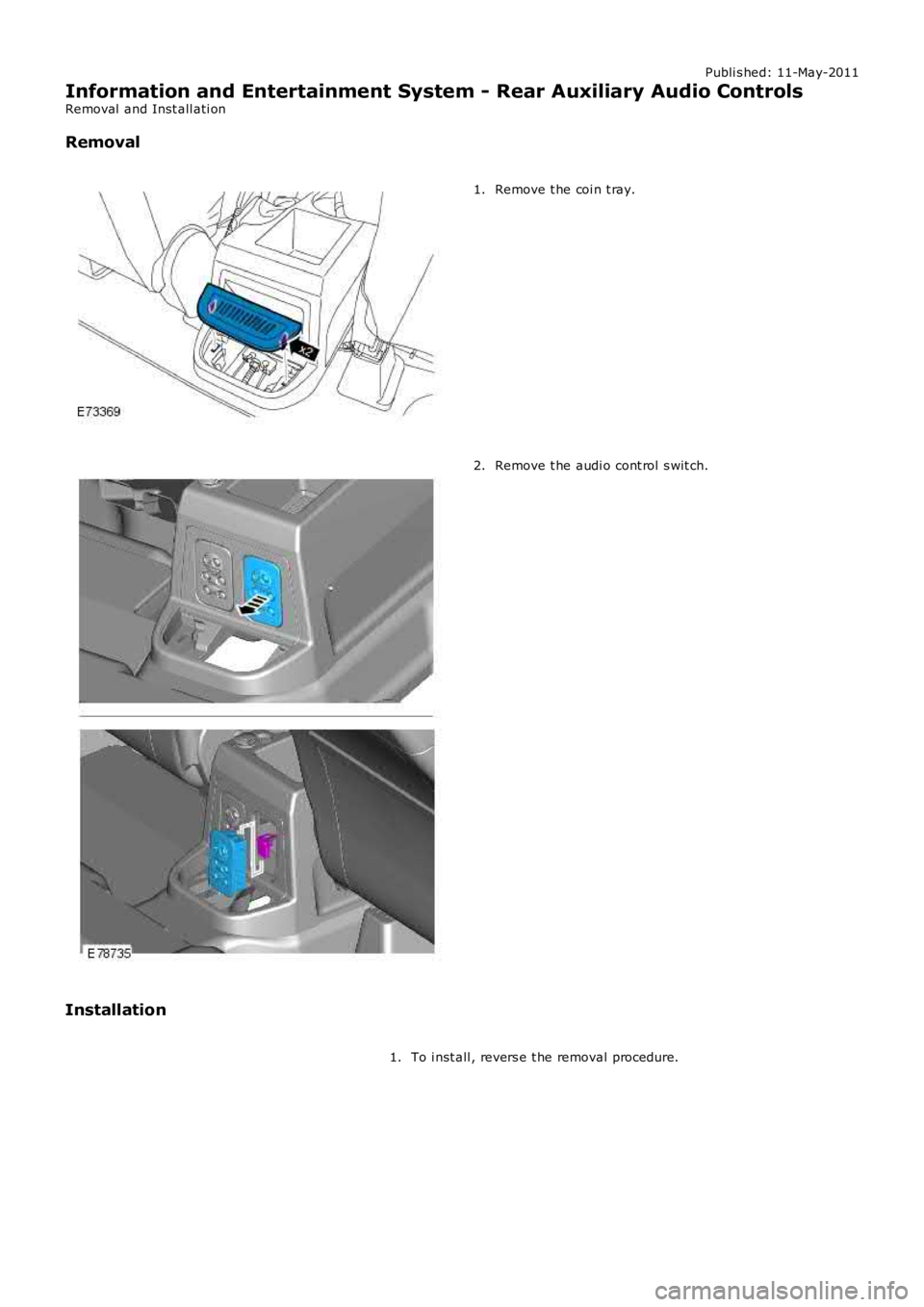
Information and Entertainment System - Rear Auxiliary Audio Controls
Removal and Inst all ati on
Removal
Remove t he coi n t ray.1.
Remove t he audi o cont rol s wit ch.2.
Installation
To i nst all , revers e t he removal procedure.1.
Page 1908 of 3229
Publi s hed: 11-May-2011
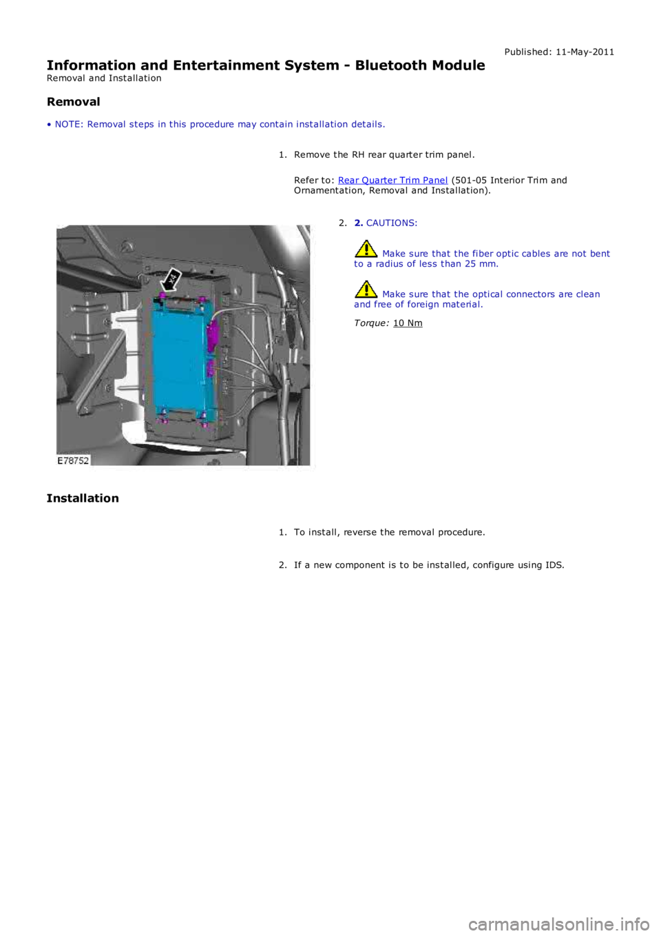
Information and Entertainment System - Bluetooth Module
Removal and Inst all ati on
Removal
• NOTE: Removal s t eps in t his procedure may cont ain i nst all ati on det ail s.
Remove t he RH rear quart er trim panel .
Refer t o: Rear Quarter Tri m Panel (501-05 Int erior Tri m and
Ornament ati on, Removal and Ins tal lat ion).
1. 2.
CAUTIONS: Make s ure that t he fi ber opt ic cables are not bent
t o a radius of les s t han 25 mm. Make s ure that t he opti cal connectors are cl ean
and free of foreign mat eri al.
T orque: 10 Nm 2.
Installation To i nst all , revers e t he removal procedure.
1.
If a new component i s t o be ins t al led, configure usi ng IDS.
2.
Page 2072 of 3229
3-Touch Screen Dis play (TAD)
4-Integrat ed Head Unit (IHU) - Hi-Li ne
5-Bl uet ooth phone module6-Ampl ifier/t uner
7-Di git al Audio Broadcas t (DAB) recei ver
8-Navigat ion computer
OVERVIEW
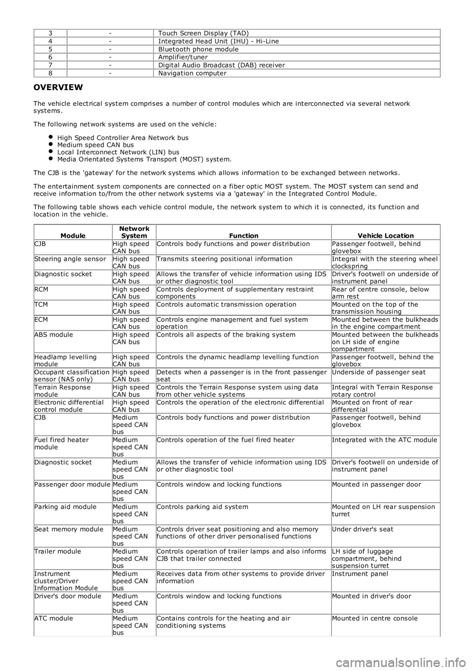
The vehi cl e elect rical s ys t em compri s es a number of control modul es which are int erconnected vi a s everal net works ys t ems .
The fol lowing net work sys tems are us ed on t he vehi cle:
High Speed Controll er Area Network busMedium speed CAN busLocal Int erconnect Network (LIN) busMedia O rient ated Sys tems Transport (MOST) s yst em.
The CJB is the 'gat eway' for the net work s yst ems whi ch allows informati on to be exchanged bet ween networks .
The entertainment s yst em components are connected on a fi ber opt ic MO ST sys t em. The MOST s ys t em can s end andreceive i nformat ion to/from t he other network s ys t ems via a 'gat eway' in the Integrat ed Control Modul e.
The fol lowing table shows each vehi cle control modul e, t he network s yst em to whi ch it i s connected, it s funct ion andlocati on in the vehicle.
ModuleNetw orkSystemFunctionVehicle Location
CJBHigh s peedCAN busControl s body functi ons and power dis t ri but ionPass enger footwell , behi ndgloveboxSt eering angle sens orHigh s peedCAN busTrans mit s s t eering pos it ional informati onInt egral wit h t he s teeri ng wheelclocks pri ngDi agnos ti c s ocketHigh s peedCAN busAll ows the trans fer of vehicle informati on usi ng IDSor other diagnos t ic t oolDri ver's footwel l on unders i de ofins trument panel
RCMHigh s peedCAN busControl s deployment of s upplementary res t raintcomponentsRear of centre cons ole, belowarm res t
TCMHigh s peedCAN busControl s automat ic t rans mi ss i on operati onMount ed on t he t op of thetransmis s ion housi ng
ECMHigh s peedCAN busControl s engine management and fuel sys t emoperati onMount ed between the bulkheadsin the engine compart ment
ABS moduleHigh s peedCAN busControl s all as pect s of the braking s yst emMount ed between the bulkheadson LH s ide of enginecompartment
Headlamp l evel li ngmoduleHigh s peedCAN busControl s t he dynami c headl amp l evell ing funct ionPass enger footwell , behi nd t heglovebox
Occupant clas si fi cat ions ensor (NAS only)High s peedCAN busDetects when a pas senger is i n t he front pas s engers eatUnders ide of pass enger seat
Terrain Res pons emoduleHigh s peedCAN busControl s t he Terrai n Res pons e s yst em us i ng dat afrom ot her vehicl e s ys t emsInt egral wit h Terrain Res pons erot ary controlElectronic different ialcont rol moduleHigh s peedCAN busControl s t he operati on of the el ect ronic di fferenti alMount ed on front of reardifferent ialCJBMedi umspeed CANbus
Control s body functi ons and power dis t ri but ionPass enger footwell , behi ndglovebox
Fuel fired heatermoduleMedi umspeed CANbus
Control s operat ion of t he fuel fi red heaterInt egrated wit h t he ATC module
Di agnos ti c s ocketMedi umspeed CANbus
All ows the trans fer of vehicle informati on usi ng IDSor other diagnos t ic t oolDri ver's footwel l on unders i de ofins trument panel
Pas senger door moduleMedi umspeed CANbus
Control s wi ndow and locki ng functi onsMount ed i n pass enger door
Parking ai d moduleMedi umspeed CANbus
Control s parking ai d s yst emMount ed on LH rear s us pensi onturret
Seat memory modul eMedi umspeed CANbus
Control s dri ver s eat posi ti oni ng and als o memoryfuncti ons of ot her driver pers onal is ed funct ionsUnder driver's s eat
Trai ler moduleMedi umspeed CANbus
Control s operat ion of t rail er lamps and als o i nformsCJB that t rai ler connect edLH s ide of l uggagecompartment , behi nds us pensi on t urret
Inst rumentclus ter/DriverInformat ion Modul e
Medi umspeed CANbus
Recei ves dat a from ot her sys t ems to provide driverinformat ionIns t rument panel
Driver's door moduleMedi umspeed CANbus
Control s wi ndow and locki ng functi onsMount ed i n dri ver's door
ATC moduleMedi umspeed CANbus
Contains controls for the heat ing and aircondi ti oni ng s ys t emsMount ed i n cent re cons ole
Page 2657 of 3229
Publ is hed: 11-May-2011
Rear End Sheet Metal Repairs - Back Panel
Removal and Installation
Removal
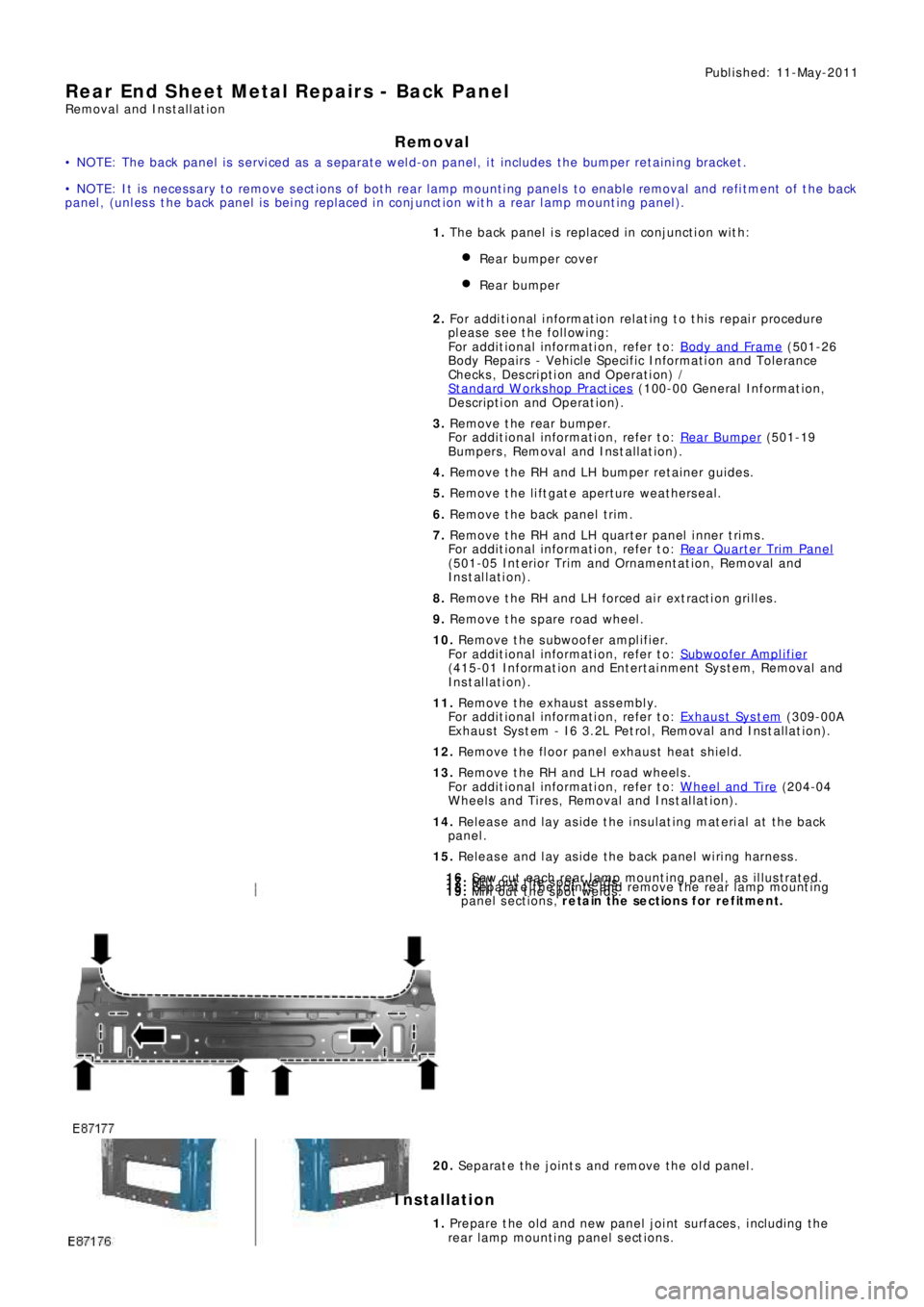
• NOTE: The back panel is serviced as a separate weld-on panel, it includes the bumper retaining bracket.
• NOTE: It is necessary to remove sections of both rear lamp mounting panels to enable removal and refitment of the back
panel , (unl es s t he back panel i s being replaced i n conjunct i on wit h a rear l amp mount ing panel ).
1. The back panel is replaced in conjunction with:
Rear bumper cover
Rear bumper
2. Fo r a d d i t i o na l i nf o rma t i o n re l a t i ng t o t hi s re p a i r p ro ce d ure
please see the following:
Fo r a d d i t i o na l i nf o rma t i o n, re f e r t o : Body and Frame
(501-26
Body Repairs - Vehicle Specific Information and Tolerance
Checks, Description and Operation) /
St a nd a rd W o rks ho p P ra ct i ce s
(100-00 Ge ne ra l I nf o rma t i o n,
Description and Operation).
3. Re move t he re a r bumpe r.
Fo r a d d i t i o na l i nf o rma t i o n, re f e r t o : Rear Bumper
(501-19
Bumpe rs , Re mo va l a nd Ins t a l l a t i on).
4. Remove the RH and LH bumper retainer guides.
5. Remove the liftgate aperture weatherseal.
6. Remove the back panel trim.
7. Remove t he RH and LH quart er panel i nner t ri ms .
Fo r a d d i t i o na l i nf o rma t i o n, re f e r t o : Rear Quarter Trim Panel
(501-05 Int eri or Trim and Ornament at i on, Removal and
Installation).
8. Remove the RH and LH forced air extraction grilles.
9. Remove the spare road wheel.
10. Remove the subwoofer amplifier.
Fo r a d d i t i o na l i nf o rma t i o n, re f e r t o : Subwoofer Amplifier
(415-01 Information and Entertainment System, Removal and
Installation).
11. Re move t he e xha us t a s s e mbl y.
Fo r a d d i t i o na l i nf o rma t i o n, re f e r t o : Exhaust Syst em
(309-00A
Exhaus t Sys t em - I6 3.2L Pet rol , Removal and Ins t all at ion).
12. Remove the floor panel exhaust heat shield.
13. Remove the RH and LH road wheels.
Fo r a d d i t i o na l i nf o rma t i o n, re f e r t o : Wheel and Tire
(204-04
Wheels and Tires, Removal and Installation).
14. Release and lay aside the insulating material at the back
panel.
15. Release and lay aside the back panel wiring harness.
16. Saw cut each rear lamp mounting panel, as illustrated.17. Mill out the spot welds.18. Separate the joints and remove the rear lamp mounting
panel sections, retain the sections for refitment.19. Mill out the spot welds.
20. Separate the joints and remove the old panel.
Installation
1. Prepare the old and new panel joint surfaces, including the
rear l amp mount i ng panel s ect ions .
Page 3025 of 3229
413-00 INSTRUMENT CLUSTER AND PANEL ILLUMINATIONFREELANDER 2 - LR2 - VIN: 000201 onwards (LHD) (01 / 01) 34
413-00 INSTRUMENT CLUSTER AND PANEL ILLUMINATION
BN,0.5BN,0.5BN,0.75BN,0.75BN,0.75
BN,0.5BN,0.75
BN,0.5BN,0.5
YE-RD,6.0RD,6.0
RD,25.0
BN,0.75
BK,35.0
BK-VT,0.75
BK-VT,1.0
BK-YE,1.5BK-GY,1.5
BK-BU,2.5
BK-YE,6.0BK-BU,6.0
BK-YE,0.5BK-GY,0.75BK-BU,2.5
BK-BU,2.5BK-YE,1.5BK-YE,2.5
BK-VT,1.5
BK-VT,0.5
C33G-7 C33H-7C22C-8 C22D-8C23E-16 C23F-16
FE17
60.0 AmpsFE18
60.0 Amps
Junction box-Battery (P147)Junction box-Central (P101)
Module (CEM) (D316)
Central Electronics
FET-IP SUPPLY
Battery (P100)12.0 Volts
wheel (D407)
Module-Steeringconsole (S350)
Switch pack-Center-Cigar lighter-Front (J112)Switch-Sun roof (S171)
C33H-8 C33G-8C22D-1 C22C-1
CAN
CAN
CANdoor (D254)
Module-Passenger-
Control (D243)
Module-Climate
control module (D371)
Information and entertainment
display (D326) Touch screen
Center Instrument panel (S425)
Switch pack-
Command Lock / Unlockwarning (S121)
Switch-Hazard-
optimisation (S380)
Switch-Terrain-
CAN
MOST
L
switch (D183)
Module-Lighting-
Audio head unit (D282)
Instrument cluster (D107)
CAN
CAN
CANdoor (D253)
Module-Driver-
Module-Rear door-LH (D405)Gearshift mechanism (D308)
LModule-Rear door-RH (D406)
LL
C2LS41-8C9PR40-2C3CA15-5C2PL13-6C3DC07C-1
S3LN17
C1BP02G-2C1BP02G-1C1BB01B-1C1BB01A-66C1DC02A-1
C1BB07G-1
BATT A
C1BP02C-54
C1BB03H-1
S2LN17
G1D108A-1
C1D134B-1
S2D134B
C2LS41-1C3DC07A-1C9PR40-4C3CA15-3
S3D127
S3D127BS3D135S9D139E
S2D139BS2D139A
G3D127-1G3D135-1G6D139-1
C2PL13-5
S2D134A
G3D134-1
Page 3051 of 3229
414-01 BATTERY, MOUNTING AND CABLES
Ground distribution
FREELANDER 2 - LR2 - VIN: 000201 onwards (LHD) (05 / 05) 63
BK-YE,0.5,2415BK-YE,0.5,1235
BK-YE,1.5,1460
BK-YE,1.5,1460
BK-YE,6.0,480
BK-YE,2.5,108
BK-YE,0.75,715BK-YE,1.5,160BK-YE,0.5,1445BK-YE,0.75,1165
BK-YE,1.5,2605
BK-YE,1.5,865
BK-YE,0.5,410BK-YE,0.75,855 (HI-LINE)BK-YE,0.5,1031BK-YE,0.75,1488BK-YE,1.0,840 (LO-LINE)
BK-YE,1.5,220
BK-YE,0.5,600
WH,2.5,1395WH,2.5,1395
BK-YE,6.0,758
BK-YE,0.5,350BK-YE,0.75,2260BK-YE,0.75,535BK-YE,0.5,2270
BK-YE,1.5,1700
WH,4.0,465
WH,2.5,1340WH,2.5,1340WH,2.5,1340WH,2.5,1340WH,1.5,1795
C33S-6 C33R-6
Switch-Sun roof (S171)control module (D117)
Roof opening paneldisplay (D326)
Touch screenElectrochromic (B179)
Mirror-
C22D-1 C22C-1
motor-Front (D258)
Control unit-Blower-gear inhibit (N182)
Solenoid-ReverseAudio head unit (D282)control module (D371)
Information and entertainmentLamp-Glove compartment (B109)Diagnostic socket (V100)
Trailer pick-up (P124)
12S
Module-Intrusion detection (T388)Sensor-Rain (T204)Mirror-Vanity-LH (B152)Rear (B104)
Lamp-Interior-Mirror-Vanity-RH (B153)Front (B100)
Lamp-Interior-frequency (RF) (T203)
Receiver-Radio-
C22C-7 C22D-7
Trailer pick-up (P124)
13 PIN
Trailer pick-up (P124)
12N
Trailer pick-up (P124)
NAS
C3RT12-1C9RW06-2
C9PR32A-10C9PR40-4C9PM05A-3C2MN08A-6
S9D139E
C2ME05A-10C2ME03B-12C3ET58-2C2LN15-2C2DB04-4C2H102-1
S2D139A
S2D139D
C1381-3
C9LN23-3
C1381-7
C9LN14B-2C9LN24-3C9LN28B-2C3PL56-2
S9D139B
S2D139B
G4AT22-1
C0499-3
S4D150C
C1382-3C0499-13C0499-11C0500-1
G4AT22X-1G6D139-1