2006 LAND ROVER FRELANDER 2 height
[x] Cancel search: heightPage 2716 of 3229
Torque: 5 NmSecure the lead in the clips.Repeat the above procedure for the other side.
LH side: Connect the ride height sensor electrical connector. 12.
Position and secure the rear shock absorbers.
Install both mass dampers.
Torque: 25 Nm
Repeat the above procedure for the other side.
13.
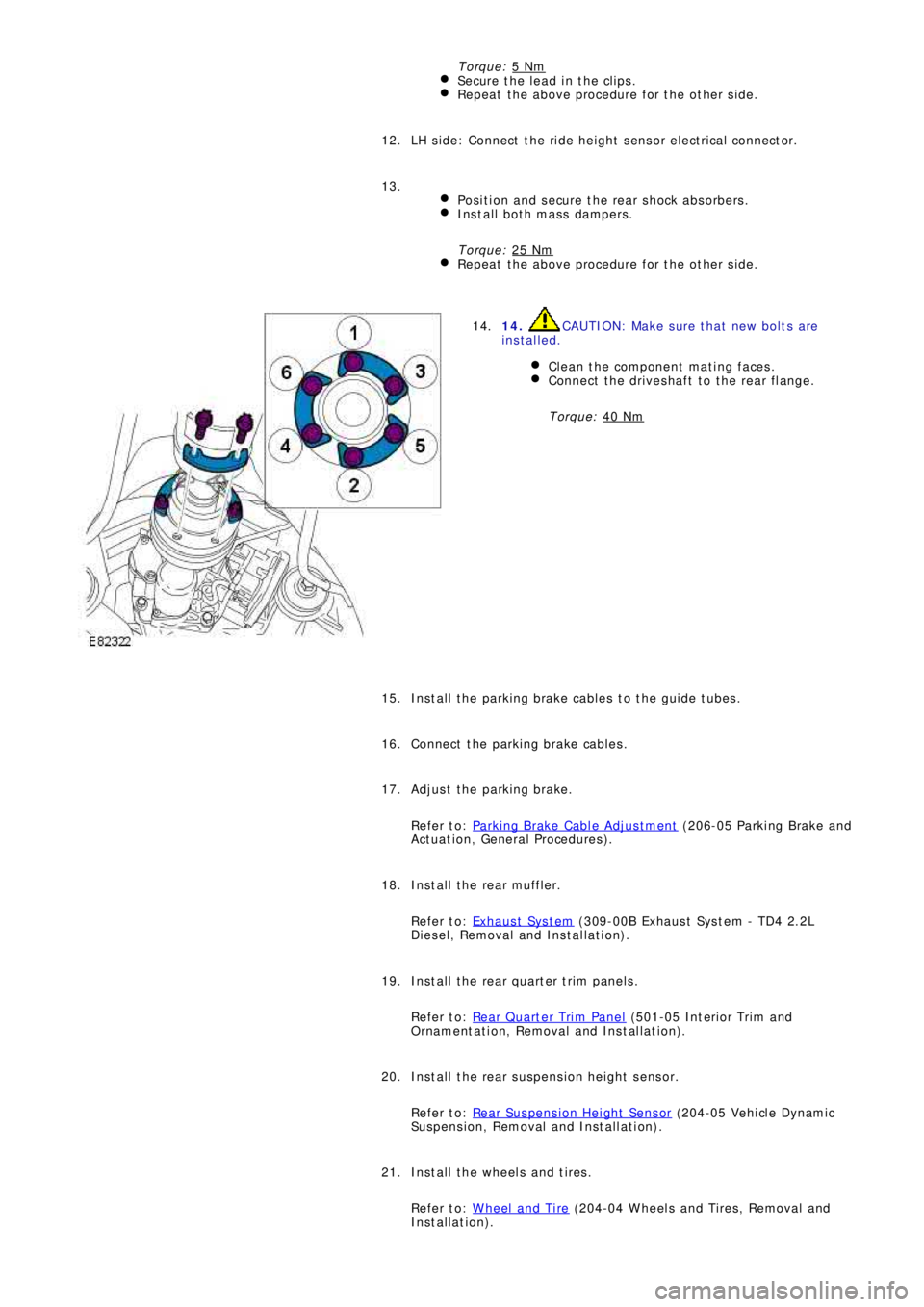
14. CAUTION: Make sure that new bolts are
installed.
Clean the component mating faces.
Connect the driveshaft to the rear flange.
Torque: 40 Nm
14.
Install the parking brake cables to the guide tubes. 15.
Connect the parking brake cables. 16.
Adjust the parking brake.
Refer to: Parking Brake Cable Adjustment
(206-05 Parki ng Brake and
Act uat i on, General Procedures ). 17.
Install the rear muffler.
Refer to: Exhaus t Sys t em
(309-00B Exhaus t Sys t em - TD4 2.2L
Diesel, Removal and Installation). 18.
Install the rear quarter trim panels.
Refer to: Rear Quarter Trim Panel
(501-05 Int eri or Tri m and
Ornament at i on, Removal and Ins t al lat i on). 19.
Install the rear suspension height sensor.
Refer to: Rear Suspension Height Sensor
(204-05 Vehi cl e Dynami c
Suspension, Removal and Installation). 20.
Install the wheels and tires.
Refer to: Wheel and Tire
(204-04 Wheels and Tires, Removal and
Installation). 21.
Page 2723 of 3229

Contents
3
R
Quick start
QUICK START ................................................... 7
Filling station information
FILLING STATION INFORMATION................... 33
Introduction
SYMBOLS GLOSSARY .................................... 35
LABEL LOCATIONS ......................................... 35
HEALTH AND SAFETY ..................................... 36
DATA RECORDING.......................................... 37
DISABILITY MODIFICATIONS ......................... 37
PARTS AND ACCESSORIES ............................ 37
Keys and remote controls
USING THE KEY .............................................. 40
GENERAL INFORMATION ON RADIO
FREQUENCIES ................................................ 40
USING THE REMOTE CONTROL ..................... 41
Locks
LOCKING AND UNLOCKING ............................ 44
Alarm
ARMING THE ALARM ..................................... 45
DISARMING THE ALARM ............................... 46
Seats
SITTING IN THE CORRECT POSITION ............ 47
MANUAL SEATS ............................................. 48
ELECTRIC SEATS ............................................ 49
HEAD RESTRAINTS ........................................ 51
REAR SEATS................................................... 51
HEATED SEATS............................................... 53
Seat belts
PRINCIPLE OF OPERATION ............................ 54
SEAT BELT REMINDER ................................... 55
FASTENING THE SEAT BELTS ........................ 56
SEAT BELT HEIGHT ADJUSTMENT................. 56
USING SEAT BELTS DURI NG PREGNANCY .... 57
Supplementary restraints system
PRINCIPLE OF OPERATION ............................ 58
AIRBAG WARNING LAMP ............................... 61
DISABLING THE PASSENGER AIRBAG ........... 62
AIRBAG SERVICE INFORMATION ................... 63
Child safety
CHILD SEATS ................................................. 64
BOOSTER CUSHIONS ..................................... 66
ISOFIX ANCHOR POINTS................................ 67
CHILD SAFETY LOCKS ................................... 69
Steering wheel
ADJUSTING THE STEERING WHEEL .............. 70
AUDIO CONTROL ........................................... 70
Lighting
LIGHTING CONTROL ...................................... 72
FRONT FOG LAMPS........................................ 72
REAR FOG LAMPS.......................................... 73
ADJUSTING THE HEADLAMPS....................... 73
HEADLAMP LEVELLING ................................. 73
HAZARD WARNING FLASHERS...................... 74
ADAPTIVE FRONT LIGHTING SYSTEM (AFS) . 74
DIRECTION INDICATORS ............................... 75
INTERIOR LAMPS .......................................... 76
APPROACH LAMPS ........................................ 76
CHANGING A BULB ........................................ 77
BULB SPECIFICATION CHART ........................ 86
Wipers and washers
WINDSCREEN WIPERS .................................. 87
RAIN SENSOR ................................................ 87
WINDSCREEN WASHERS............................... 88
HEADLAMP WASHERS................................... 88
REAR WINDOW WIPER AND WASHERS ........ 89
ADJUSTING THE WINDSCREEN WASHER JETS .
89
CHECKING THE WIPER BLADES .................... 90
CHANGING THE WIPER BLADES.................... 90
Windows and mirrors
ELECTRIC WINDOWS ..................................... 93
EXTERIOR MIRRORS ..................................... 94
ELECTRIC EXTERIOR MIRRORS .................... 95
INTERIOR MIRROR ........................................ 96
Instruments
INSTRUMENT PANEL OVERVIEW .................. 97
Information displays
TRIP COMPUTER ........................................... 99
INFORMATION MESSAGES ............................ 99
Page 2730 of 3229
10
Quick start
L
Power operated seat adjustment
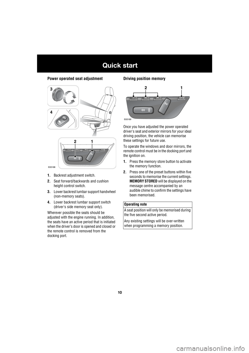
1. Backrest adjustment switch.
2. Seat forward/backwards and cushion
height control switch.
3. Lower backrest lumbar support handwheel
(non-memory seats).
4. Lower backrest lumbar support switch
(driver's side memory seat only).
Wherever possible the seats should be
adjusted with the engine running. In addition,
the seats have an active period that is initiated
when the driver’s door is opened and closed or
the remote control is removed from the
docking port.
Driving position memory
Once you have adjusted the power operated
driver's seat and exterior mirrors for your ideal
driving position, the vehicle can memorise
these settings for future use.
To operate the windows and door mirrors, the
remote control must be in the docking port and
the ignition on.
1. Press the memory store button to activate
the memory function.
2. Press one of the preset buttons within five
seconds to memorise the current settings.
MEMORY STORED will be displayed on the
message centre accompanied by an
audible chime to confirm the settings have
been memorised.
E83188
12
3
4
Operating note
A seat position will onl y be memorised during
the five second active period.
Any existing settings w ill be over-written
when programming a memory position.
E83189
12
Page 2731 of 3229
11
Quick start
R
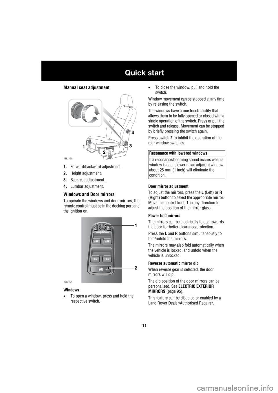
Manual seat adjustment
1. Forward/backward adjustment.
2. Height adjustment.
3. Backrest adjustment.
4. Lumbar adjustment.
Windows and Door mirrors
To operate the windows and door mirrors, the
remote control must be in the docking port and
the ignition on.
Windows
• To open a window, press and hold the
respective switch. •
To close the window, pull and hold the
switch.
Window movement can be stopped at any time
by releasing the switch.
The windows have a one touch facility that
allows them to be fully opened or closed with a
single operation of the switch. Press or pull the
switch and release. Mo vement can be stopped
by briefly pressing the switch again.
Press switch 2 to inhibit the operation of the
rear window switches.
Door mirror adjustment
To adjust the mirrors, press the L (Left) or R
(Right) button to select the appropriate mirror.
Move the control knob 1 in any direction to
adjust the position of the mirror glass.
Power fold mirrors
The mirrors can be electr ically folded towards
the door for better clearance/protection.
Press the L and R buttons simultaneously to
fold/unfold the mirrors.
The mirrors may also fold automatically when
the vehicle is locked, and unfold when the
vehicle is unlocked.
Reverse automatic mirror dip
When reverse gear is selected, the door
mirrors will dip.
The dip position of the door mirrors can be
personalised. See ELECTRIC EXTERIOR
MIRRORS (page 95).
This feature can be disabled or enabled by a
Land Rover Dealer/A uthorised Repairer.
3
2
1
E83190
4
1
2
E83191
Resonance with lowered windows
If a resonance/booming sound occurs when a
window is open, lowering an adjacent window
about 25 mm (1 inch) will eliminate the
condition.
Page 2732 of 3229
12
Quick start
L
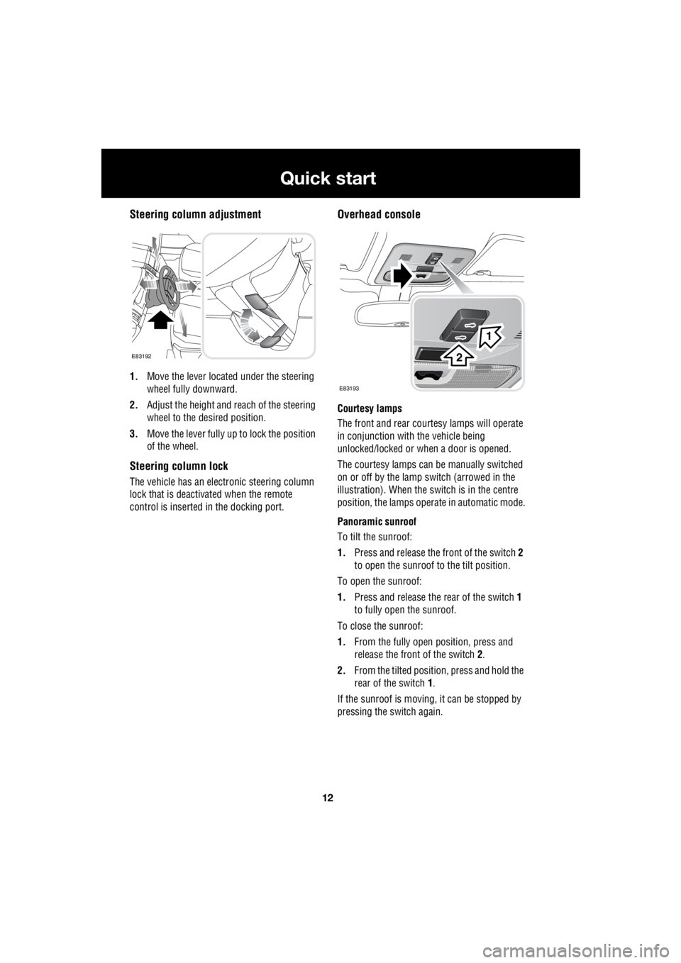
Steering column adjustment
1. Move the lever located under the steering
wheel fully downward.
2. Adjust the height and reach of the steering
wheel to the desired position.
3. Move the lever fully up to lock the position
of the wheel.
Steering column lock
The vehicle has an electronic steering column
lock that is deactivated when the remote
control is inserted in the docking port.
Overhead console
Courtesy lamps
The front and rear cour tesy lamps will operate
in conjunction with the vehicle being
unlocked/locked or when a door is opened.
The courtesy la mps can be manually switched
on or off by the lamp switch (arrowed in the
illustration). When the switch is in the centre
position, the lamps opera te in automatic mode.
Panoramic sunroof
To tilt the sunroof:
1. Press and release the front of the switch 2
to open the sunroof to the tilt position.
To open the sunroof:
1. Press and release the rear of the switch 1
to fully open the sunroof.
To close the sunroof:
1. From the fully open position, press and
release the front of the switch 2.
2. From the tilted positi on, press and hold the
rear of the switch 1.
If the sunroof is moving, it can be stopped by
pressing the switch again.
E83192
E83193
1
2
Page 2768 of 3229
Seats
48
L
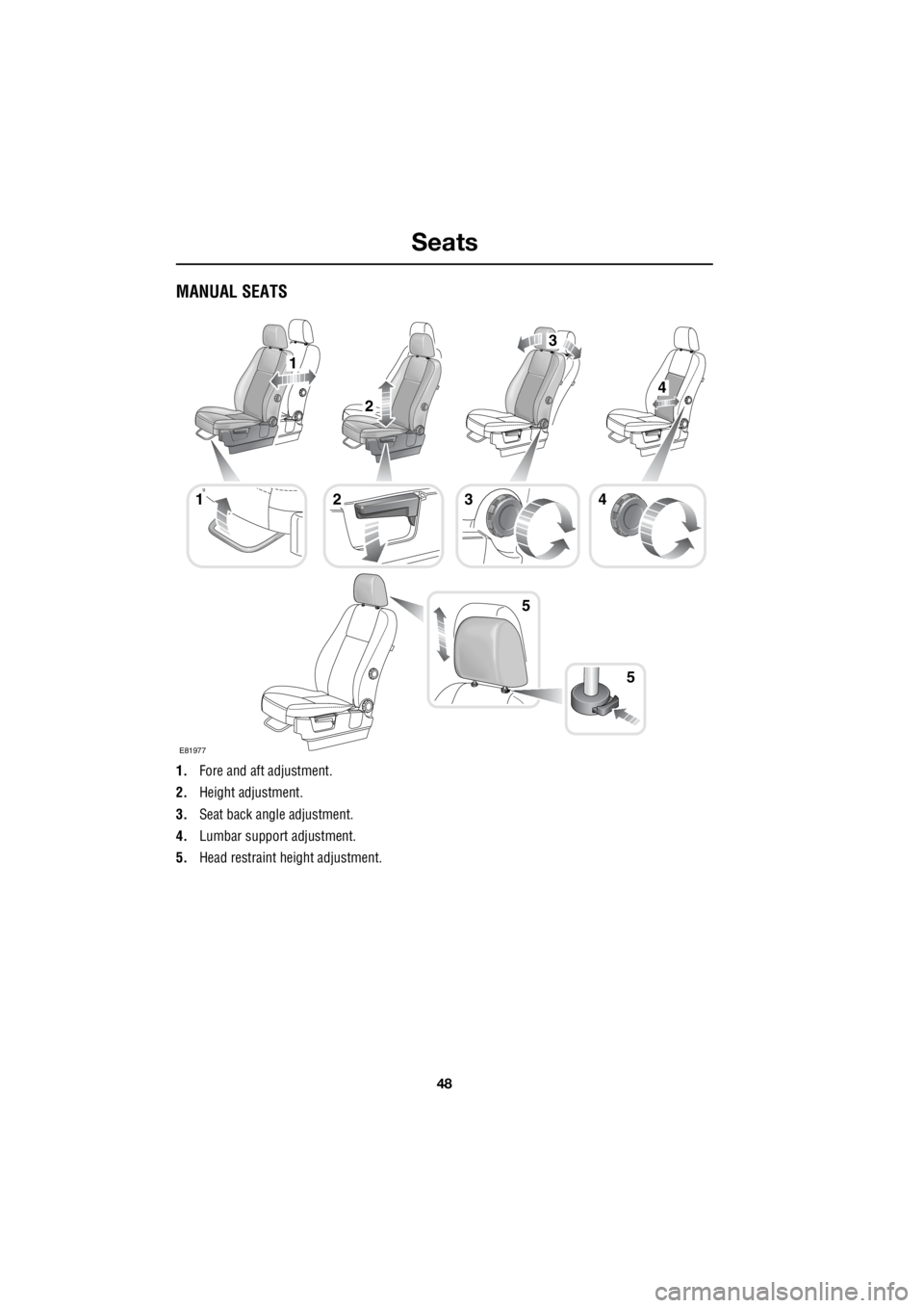
MANUAL SEATS
1. Fore and aft adjustment.
2. Height adjustment.
3. Seat back angle adjustment.
4. Lumbar support adjustment.
5. Head restraint he ight adjustment.
1
5
1
2
4
3
423
5
E81977
Page 2769 of 3229
49
Seats
R
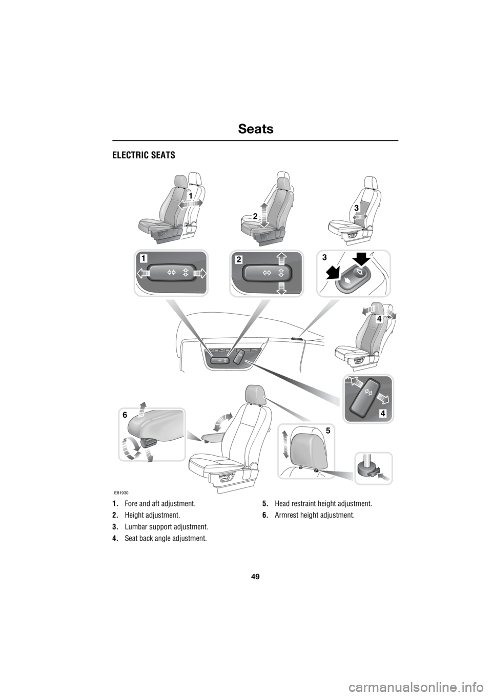
ELECTRIC SEATS
1. Fore and aft adjustment.
2. Height adjustment.
3. Lumbar support adjustment.
4. Seat back angle adjustment. 5.
Head restraint height adjustment.
6. Armrest height adjustment.
123
46
5
1
23
4
E81930
Page 2776 of 3229
Seat belts
56
L
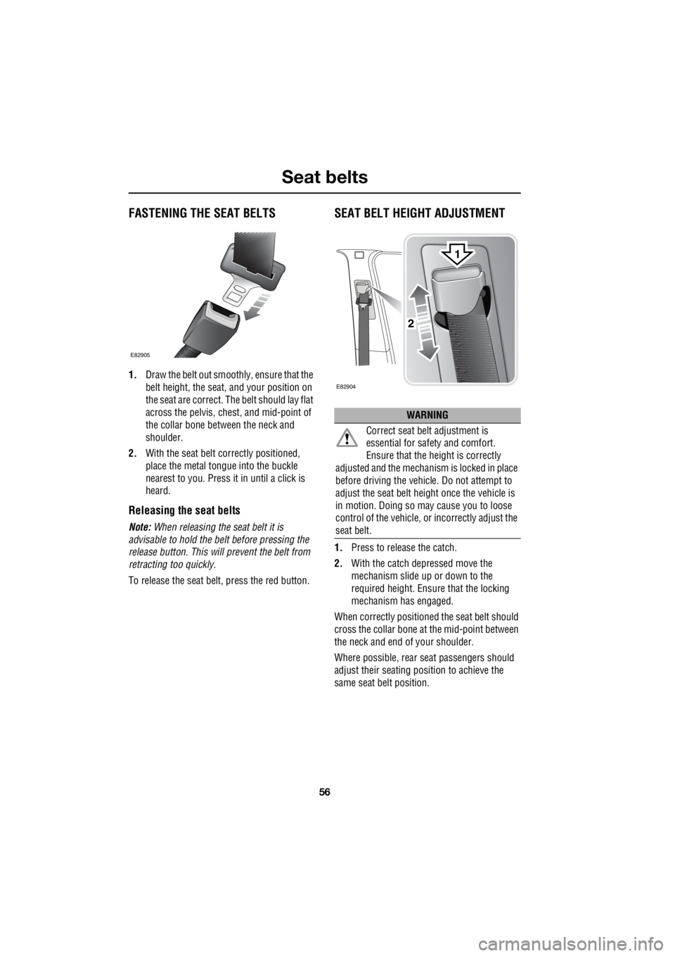
FASTENING THE SEAT BELTS
1. Draw the belt out smoothly, ensure that the
belt height, the seat, and your position on
the seat are correct. The belt should lay flat
across the pelvis, chest, and mid-point of
the collar bone between the neck and
shoulder.
2. With the seat belt correctly positioned,
place the metal tongue into the buckle
nearest to you. Press it in until a click is
heard.
Releasing the seat belts
Note: When releasing the seat belt it is
advisable to hold the belt before pressing the
release button. This will prevent the belt from
retracting too quickly.
To release the seat be lt, press the red button.
SEAT BELT HEIGHT ADJUSTMENT
1.Press to release the catch.
2. With the catch depressed move the
mechanism slide up or down to the
required height. Ensure that the locking
mechanism has engaged.
When correctly positione d the seat belt should
cross the collar bone at the mid-point between
the neck and end of your shoulder.
Where possible, rear se at passengers should
adjust their seating position to achieve the
same seat belt position.
E82905
WARNING
Correct seat belt adjustment is
essential for safe ty and comfort.
Ensure that the hei ght is correctly
adjusted and the mechanism is locked in place
before driving the vehicl e. Do not attempt to
adjust the seat belt height once the vehicle is
in motion. Doing so ma y cause you to loose
control of the vehicle, or incorrectly adjust the
seat belt.
E82904
2
1