2006 LAND ROVER FRELANDER 2 brakes
[x] Cancel search: brakesPage 520 of 3229
25-Sol enoi d-operated inlet valve (LH rear brake)
26-Sol enoi d-operated inlet valve (RH front brake)
The HCU features 3 operati ng modes:
Normal braki ng/ EBDABS brakingActi ve braking.
Normal Braking/EBD Mod e
Ini ti ally, all of t he s olenoi d-operat ed val ves are de-energi zed. Operat ing the brake pedal produces a corres pondi ngincreas e or decreas e of press ure in t he brakes , through t he open pil ot val ves and i nlet valves. If t he ABS moduledetermines t hat EBD is necess ary, i t energi zes the i nlet valves for both the rear brakes , t o i sol at e t he brakes from anyfurther increas e i n hydraulic press ure.
• NOTE: Only the rear brakes are control led by the EBD funct ion.
ABS Braking Mode
If the ABS modul e determines t hat ABS braking i s neces sary, it energizes t he inl et and out let valves of the relat ed brakeand s tarts t he hydrauli c ret urn pump. The i nl et val ve cl oses to i s ol ate the brake from pres s uri zed flui d; the out let valveopens to releas e pres s ure from the brake int o t he accumulat or, and t he ret urn pump ci rcuit . The reduced hydraul ic pres s ureall ows the wheel t o accelerate. The ABS module then operat es the i nlet and outl et val ves t o modul at e t he pres s ure i n t hebrake t o apply t he maximum braking effort wit hout locki ng the wheel . Cont rol of the val ves for each wheel takes placeindivi dual ly.
Active Braking Mode
The act ive braki ng mode i s us ed to generat e and control hydrauli c pres s ure t o t he brakes for funct ions other t han Normaland ABS braking, for example RSC, DSC, EBA, ETC, HDC.
For act ive braking, t he ABS module energi zes the pi lot valves and pri ming valves , start s t he ret urn pump and energizes allof the inlet valves. Brake fl uid, drawn from t he res ervoir t hrough the mast er cyl inder and priming valve, is press uri zed byt he ret urn pump and suppli ed to the i nlet valves. The ABS modul e t hen operat es t he inl et valves and out let val ves , asrequired, to modul at e t he pres s ure i n t he indivi dual brakes . Some noi s e may be generat ed during act ive braki ng.
Service Information
The ABS module compris es an HCU and an Elect roni c Cont rol Unit (ECU) t hat mus t not be s eparated. The ABS module andHCU as s embly i s s uppl ied as a si ngl e component and arrives i n a pre-fill ed s tat e.
• NOTE: The ABS module, HCU and the s ens or clus t er are fragil e components and mus t be dis carded if dropped ordamaged.
CONTROL DIAGRAM
• NOTE: A = Hardwi red; D = Hi gh Speed CAN bus ; N = Medi um Speed CAN bus ; U = Pri vat e CAN bus
Page 522 of 3229

12-LH front wheel s peed s ens or
13-RH rear wheel s peed sens or
14-Act ive On-Demand Coupling modul e15-ECM
16-Diagnost ic socket
17-Sens or clus ter18-Terrai n Res pons e™ control modul e
19-Trans mis s ion Cont rol Modul e (TCM) - aut omati c t rans mis s ion models onl y
20-CJB
PRINCIPLES OF OPERATION
Anti-Lock Brake System
ABS cont rol s t he s peed of all road wheel s t o ensure opti mum wheel s li p when braking at the adhesi on li mit . The wheelsare prevent ed from locki ng to ret ai n effecti ve st eeri ng cont rol of the vehicle.
The front brake pres s ures are modul ated s eparat el y for each wheel. The rear brake press ures are modulat ed by s elect low.Select low appli es the same pres sure t o both rear brakes, wi th the press ure level bei ng det ermined by t he wheel on thelower fri ct ion s urface. This maint ai ns rear s tabil it y on s pli t fricti on s urfaces .
Corner Brake Control
CBC i nfluences the brake pres sures , below and wit hin ABS thres holds , to counteract the yawing moment produced whenbraking i n a corner. CBC produces a correcti on t orque by li mi ti ng the brake pres sure on one s ide of t he vehicle.
Dynamic Stability Control
DSC us es brakes and powert rain torque control to as s is t i n maint aining the l ateral st abi lit y of t he vehi cl e. W hil e t heignit ion is energi zed t he DSC funct ion i s permanentl y enabl ed, unl es s s elect ed off us ing t he DSC s wit ch. Even i f DSC isdesel ect ed, driving maneuvers wi th ext reme yaw or lat eral accelerat ion may trigger RSC acti vi ty to as s is t t he vehi cl es tabil it y.
DSC enhances dri ving s afet y in abrupt maneuvers and in under-st eer or over-s teer s ituat ions t hat may occur in a bend. TheABS module monit ors t he yaw rat e and l ateral accel erati on of the vehicle, s t eering input , and then s elect ively appli esindivi dual brakes and s ignals for powertrain t orque adjus t ments t o reduce under-s teer or over-s teer.
In general:
In an under-s t eer s i tuati on; the i nner wheels are braked t o count eract the yaw movement t owards t he outer edgeof the bend.In an over-st eer si tuat ion; the out er wheel s are braked to prevent t he rear end of the vehicl e from pus hing t owardst he out er edge of t he bend.
The ABS module monit ors t he tracki ng s tabil it y of the vehicle usi ng inputs from t he wheel s peed s ens ors, t he s teeringangl e s ensor, and the yaw rat e and lat eral accelerat ion sens or. The t racki ng s tabil it y is compared wit h s t ored t arget dat a.W henever t he t racki ng s tabil it y devi ates from t he target dat a, t he ABS modul e int ervenes by appl yi ng the appropriat ebrakes.
The fol lowing interact ions occur i n an i nt erventi on s it uat ion:
High speed CAN s i gnal t o t he ECM, to reduce engine torque.High speed CAN s i gnal t o t he Act ive On-demand Coupl ing module, t o open t he locki ng torque of the centercoupl ing.Applicati on of braking t o t he appropri at e corner of the vehicl e.
Electronic Brake Force Distribution
EBD l imi ts the brake press ure appl ied t o t he rear wheels . W hen t he brakes are appl ied, the wei ght of t he vehicle t rans fersforwards , reduci ng t he abi li ty of t he rear wheels to t rans fer braki ng effort t o t he road s urface. This may caus e t he rearwheels t o s li p and make t he vehi cl e uns table.
EBD us es the ant i-lock braking hardware t o automat icall y opti mize t he pres s ure of t he rear brakes , bel ow t he point whereABS i s normall y i nvoked.
• NOTE: Only the rear brakes are control led by the EBD funct ion.
Electronic Traction Control
ETC att empt s to opt imize forward tract ion by reduci ng engi ne torque, or by applying t he brake of a spi nni ng wheel unt ilt racti on is regai ned.
ETC is act ivated if an i ndi vi dual wheel speed i s above that of the vehicle reference speed (pos i ti ve sl ip) and t he brakepedal i s not pres sed. The brake i s appl ied t o t he s pinning wheel, al lowing t he excess t orque t o be t rans mit t ed to thenon-s pinning wheels through t he dri ve li ne. If neces s ary, the ABS modul e als o s ends a hi gh speed CAN bus mess age t ot he ECM t o reques t a reducti on in engine torque.
W hen t he DSC funct ion i s s elected off us i ng the DSC s wit ch, t he engi ne t orque reducti on feature i s dis abl ed.
Emergency Brake Assist
EBA as si s ts t he driver in emergency braking si tuat ions by automat icall y maximi zi ng the appl ied braki ng effort . There aret wo s it uat ions when t he ABS module wil l invoke EBA:
Page 523 of 3229
W hen t he brake pedal is rapi dly press ed.W hen t he brake pedal is pres s ed hard enough t o bri ng t he front brakes i nto ABS operati on.
W hen t he brake pedal is rapi dly press ed, the ABS modul e i ncreas es t he hydraul ic press ure to al l of the brakes unt il t het hreshol d for ABS operat ion i s reached. This act ion appli es the maxi mum braking effort for the avail abl e t racti on. The ABSmodule moni tors for t he s udden appli cat ion of t he brakes , us i ng inputs from t he brake pedal s wi tch and from the press ures ens or wit hin the HCU. W it h t he brake pedal pres s ed, if t he rat e of increas e of hydraul ic press ure exceeds thepredetermined l imi t, t he ABS modul e invokes emergency braki ng.
W hen t he brake pedal is pres s ed hard enough t o bri ng t he front brakes i nto ABS operati on, t he ABS module increas es thehydraulic press ure to the rear brakes up to the ABS thres hold.
EBA operat ion cont inues unti l the driver rel eas es t he brake pedal , s uffi cientl y for t he hydraulic press ure in the HCU to dropbelow a threshold val ue s tored in t he ABS modul e.
Engine Drag-Torque Control
EDC prevents wheel s li p caus ed by any of t he fol lowing:
A s udden decreas e i n engine t orque when t he accelerator is suddenly released.The s udden engagement of t he clutch after a downs hift on manual t rans mi ss ion vehicl es .A downs hift us i ng the CommandShift functi on on automat ic t rans mi ss ion vehicl es .
W hen t he ABS module det ects t he ons et of wheel s lip wit hout t he brakes being appli ed, t he ABS module s ignal s t he ECMvia t he high speed CAN bus t o reques t a moment ary increase in engine torque.
Hill Descent Control
HDC us es engine braking and brake int ervent ion to control the vehicle speed and accel erati on duri ng low speed off-roaddescents , and in low grip on-road condit ions. General ly, equal pres s ure i s applied to al l 4 brakes , but pres s ure to individualbrakes may be modi fi ed by t he ABS and DSC funct ions to ret ain t he vehi cles s tabil it y. Sel ect ion of t he HDC funct ion i scont rol led by t he HDC s wi tch l ocat ed on t he fl oor consol e. HDC operates at vehicle speeds up t o 50 km/h (31 mph).
W ARNING: Incorrect us e of the HDC functi on may compromis e t he s tabil it y of the vehicle, resul ti ng in a dangerousand uncont roll ed hil l des cent . Pres si ng t he cl utch pedal and/or driving wit h t he trans mi s si on in 'Neutral' whil e HDC i sact ive, wi ll prevent engine braking from ass is t ing t he vehicle. The brakes wil l overheat and i nduce t he HDC fade outs trategy. In this condit ion t here will be no cont rol over t he vehi cl e duri ng a des cent .
• NOTE: W i th the HDC functi on s elect ed, HDC i s operati ve even when the clut ch pedal is pres sed or t he t rans mis s ion i s int he 'Neutral' posi ti on. It is not recommended t o drive t he vehi cl e furt her t han is abs olut el y neces s ary wi th HDC s elected,and t he cl utch pedal press ed/ or the t rans mi ss i on in 'Neut ral '.
On manual transmis s ion vehicles , HDC may be us ed i n firs t and reverse gears only. Once the vehicle is movi ng, t he clut chpedal i s to be ful ly releas ed. The vehicle i s not recommended to be dri ven wit h HDC act ive and t he transmis si on in'Neut ral'.
On aut omati c trans mi s si on vehi cl es, HDC may be us ed i n 'D' dri ve, 'R' revers e and CommandShi ft '1' only. W hen in 'D', t heTCM wi ll automat icall y s el ect t he mos t appropri ate gear. The vehicle is not recommended t o be driven wit h HDC act ive andt he trans mi s si on in 'Neutral'.
HDC i s able t o be sel ect ed at speeds up t o 80 km/h (50 mph), but wi ll only be enabled at s peeds bel ow 50 km/h (31 mph).
W hen HDC is s elect ed:
At s peeds up t o 50 km/h (31 mph), the HDC informat ion i ndi cat or lamp i s permanentl y i llumi nated i f a valid gear i ss elect ed.At s peeds bet ween 50 to 80 km/h (31 to 50 mph), t he HDC i nformat ion indicator lamp fl ashes and on vehicles wit ht he high l ine i ns t rument clus ter, a mes s age advis i ng that t he s peed i s t oo high i s dis played in the mes s age cent er.If the HDC swit ch is pres s ed whil e t he vehi cl e s peed is great er than 80 km/h (50 mph), the HDC informat ionindicat or l amp wi ll not il lumi nat e and HDC will not be s elected.If the s peed reaches 80 km/h (50 mph) or more, a warni ng chi me i s s ounded, the HDC functi on is swi tched off, t heinformat ion i ndi cat or lamp is exti ngui shed and, on vehicles wi th the hi gh li ne ins trument cl ust er, a mess ageadvi s ing t hat HDC has been swi tched off i s dis played i n the mess age center.
For addit ional informat ion, refer t o:
Ins trument Clus ter (413-01 Ins t rument Clus t er, Descripti on and Operat ion),Informat ion and Mes s age Cent er (413-08 Informati on and Mes sage Cent er, Descripti on and Operat ion).
W hen HDC is enabled, the ABS module calculat es a t arget speed and compares t his wi th the act ual vehicle s peed. The ABSmodule t hen operates the HCU in t he acti ve braking mode as required, t o achi eve and maint ain t he t arget speed.Operat ion of t he vehi cl e s toplamps during HDC is controll ed by the CJB.
Applying t he foot brake during acti ve braking may res ult i n a puls e being felt t hrough t he brake pedal.
The t arget speed vari es bet ween mi nimum and maximum values for each gear and t rans miss ion range, dependi ng on driverinputs through t he foot pedals . If the foot pedals are not operated, t he ABS module adopts a default t arget s peed:
HDC Target Speeds
T arget Speed
Automatic T ransmission GearManual T ransmission Gear
1st and DriveReverse1stReverseDefaul t10 km/h (6 mph)3.5 km/h (2.2 mph)10 km/h (6 mph)8 km/h (5 mph)
Mi ni mum6 km/h (3.7 mph)3.5 km/h (2.2 mph)7.5 km/h (4.7 mph)8 km/h (5 mph)
Maximum20 km/h (12.4 mph)3.5 km/h (2.2 mph)20 km/h (12.4 mph)8 km/h (5 mph)The t arget speed i s varied bet ween the mini mum and maxi mum values us ing the accel erator pedal, or by pres s ing t he
Page 524 of 3229
s peed control '+' and '-' but t ons (dependant on vehi cl e s peci fi cat ion). The HDC Target speed wi ll als o vary depending ont he Terrai n Respons e™ mode sel ect ed.
Duri ng changes of target s peed, the ABS modul e li mit s vehicle decelerat ion and accelerat ion t o -0.5 met ers per s econd
s quared (m/s2) (-1.64 feet per s econd squared (ft/s2)); and +0.5 m/s2 (+1.64 ft/s2) res pect ively.
To provide a s afe t rans it ion from acti ve braking t o brakes off, the ABS module i nvokes a fade out st rat egy that graduall yrel eas es t he braking effort during act ive braking. The fade out s t rat egy occurs i f any of t he fol lowi ng condit ions i s detectedduri ng act ive braki ng:
HDC i s s elected off us i ng the HDC s wit ch.Failure of a component us ed by HDC, but not crit ical t o fade out funct ion.Accelerator pedal pres s ed when t rans mis s ion i s i n neut ral .Brakes overheat .
If fade out is i nvoked becaus e of HDC de-s el ect ion or component failure, the HDC functi on is cancel led by t he ABS module.If fade out is i nvoked becaus e t he accelerator pedal i s pres s ed wit h t he t ransmis s ion i n neut ral , or because of brakeoverheat , t he HDC funct ion remains in s tandby and res umes operati on when t he accelerat or pedal is releas ed or the brakeshave cooled.
The fade out s t rategy i ncreas es t he t arget speed at a cons tant accelerati on rat e of 0.5 m/s2 (1.64 ft/s2), unti l themaximum t arget speed i s reached, or unti l no act ive braki ng is required for 0.5 second. If t he accelerat or pedal is
posi ti oned wit hin t he range t hat infl uences t arget s peed, the accelerat ion rate is increas ed t o 1.0 m/s2 (3.3 ft /s2).
W hen fade out is i nvoked becaus e of component fai lure, a warning chime is sounded and the HDC informat ion i ndi cat orlamp is ext inguis hed. The HDC warning i ndicat or lamp is t hen il lumi nat ed (on low-li ne ins trument cl ust er), or a mes s ageadvi s ing of t he fault i s dis played in the mess age cent er (on hi gh-l ine i ns t rument clus ter).
For addit ional informat ion, refer t o:
Ins trument Clus ter (413-01 Ins t rument Clus t er, Descripti on and Operat ion),Informat ion and Mes s age Cent er (413-08 Informati on and Mes sage Cent er, Descripti on and Operat ion).
W hen fade out is i nvoked becaus e of brake overheat, on vehicles wi th the hi gh-li ne ins t rument clus ter, a mes sage advis ingt hat HDC is t emporarily unavail abl e is di s pl ayed. On vehicles wit h t he low-line ins trument cl us t er, t he HDC warningindicat or l amp flas hes . At t he end of fade out, t he HDC informati on indicat or flas hes. The flas hing warni ng and informat ionindicat or l amps, and/or di spl ayed mes s age cont inue whi le HDC remai ns sel ect ed, unt il t he brakes have cooled.
For addit ional informat ion, refer t o:
Ins trument Clus ter (413-01 Ins t rument Clus t er, Descripti on and Operat ion),Informat ion and Mes s age Cent er (413-08 Informati on and Mes sage Cent er, Descripti on and Operat ion).
To monit or for brake overheat, t he ABS modul e monit ors t he amount of braking acti vi ty and, from thi s, es ti mat es thet emperature of each brake. If the es t imat ed temperature of any brake exceeds a pres et li mit , t he ABS module i nvokes t hefade out s t rategy. Aft er the fade out cycle, t he HDC funct ion i s re-enabl ed when the ABS modul e es ti mates that all of thebrake t emperatures are at l ess than 64% of the preset t emperat ure l imi t.
Roll Stability Control
The RSC funct ion us es the brakes and the engine t o at tempt t o rest ore vehicle s tabilit y, i f the vehicle is forced i nt o ahars h maneuver t hat ri sks i t ti pping over.
The ABS module monit ors dri ver i nput s and vehicle behavior usi ng various powert rai n s ignals and t he i nput s from thewheel s peed s ens ors, t he s teering angle s ens or, the roll rate sens or, yaw rate and lateral accel erat ion s ensors. Thes einputs are compared wit h modeled behavi or and, if t he vehicle behavior reaches a given ris k level, t he ABS module cut st he engi ne power, or brakes one or more wheels suffi ci ent ly to al low the vehicle to regain s t abi li ty and hel p the driverremai n i n cont rol .
W hi le t he i gni ti on is energi zed, RSC i s permanentl y enabl ed even if t he DSC functi on is sel ect ed off.
Terrain Response™ System Integration
The Terrai n Res pons e™ funct ion integrat es t he ABS and other vehicle s ys tem cont rol modules t o as si s t the vehicle whendri vi ng off-road or during di fficult s urface condit ions . Terrai n Respons e is act ivated when the rotary cont rol s wit ch is s et t oa Terrain Res ponse special program.
W hen a Terrai n Respons e s peci al program i s acti vat ed, t he ABS module along wi th ot her vehicle s ys t em control modul eswil l operate in accordance wi th programmed software maps . The s oftware maps al low t he ABS s ys tem to functi on wit h at hreshol d that wi ll as si s t the s elected Terrai n Respons e s pecial program.For addit ional informat ion, refer t o: Ride and Handli ng Opti mizat ion (204-06 Ride and Handli ng Opt imi zat ion, Descripti onand Operat ion).
Page 1281 of 3229
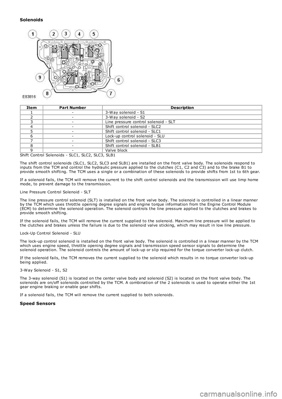
Solenoids
ItemPart NumberDescription
1-3-W ay s olenoi d - S1
2-3-W ay s olenoi d - S23-Line press ure cont rol s ol enoi d - SLT
4-Shift cont rol s ol enoi d - SLC2
5-Shift cont rol s ol enoi d - SLC16-Lock-up cont rol s olenoi d - SLU
7-Shift cont rol s ol enoi d - SLC3
8-Shift cont rol s ol enoi d - SLB19-Valve bl ock
Shift Cont rol Solenoids - SLC1, SLC2, SLC3, SLB1
The s hift control sol enoi ds (SLC1, SLC2, SLC3 and SLB1) are ins tal led on t he front valve body. The s olenoids respond t oinputs from t he TCM and control the hydrauli c pres s ure appli ed to the clut ches (C1, C2 and C3) and to the brake B1 t oprovide s moot h s hifti ng. The TCM us es a si ngl e or a combinat ion of t hes e s olenoids to provi de shi ft s from 1s t t o 6t h gear.
If a s ol enoi d fai ls , t he TCM wi ll remove t he current t o t he s hift cont rol s ol enoi ds and the trans mi s si on wil l use limp homemode, to prevent damage t o t he transmis s ion.
Line Pres s ure Cont rol Solenoid - SLT
The li ne pres s ure control s olenoid (SLT) is i nst all ed on t he front val ve body. The sol enoi d i s cont roll ed in a l inear mannerby t he TCM which us es t hrott le openi ng degree s ignals and engine t orque i nformat ion from t he Engi ne Control Module(ECM) t o det ermi ne the sol enoid operati on. The s olenoid controls t he l ine pres s ure appli ed t o t he cl utches and brakes toprovide s moot h s hifti ng.
If the s olenoid fail s, t he TCM will remove the current s uppl ied t o t he s ol enoi d. Maxi mum l ine press ure wil l be appl ied t ot he cl utches and brakes unl ess the fail ure i s due t o the sol enoi d val ve s ti cki ng, whi ch may res ult i n low li ne pres s ure.
Lock-Up Cont rol Solenoid - SLU
The lock-up control sol enoid is i nst all ed on t he front val ve body. The s ol enoi d i s cont roll ed in a l inear manner by t he TCMwhich us es engi ne s peed, t hrott le openi ng degree s ignals and t rans mis s ion s peed s ensor s ignals t o det ermi ne thes olenoi d operat ion. The sol enoi d cont rol s the amount of l ock-up or s l ip requi red for the t orque converter l ock-up cl utch.
If the s olenoid fail s, t he TCM removes the current s uppli ed t o t he sol enoi d which resul ts i n no t orque converter l ock-upbeing appli ed.
3-W ay Solenoi d - S1, S2
The 3-way sol enoid (S1) i s located on t he center valve body and s ol enoi d (S2) i s located on the front valve body. Thes olenoi ds are on/off s olenoids control led by the TCM. A combi nat ion of t he 2 s olenoids i s us ed to operat e ei ther the 1s tgear engine braki ng or enabl e gear s hift s.
If a s ol enoi d fai ls , t he TCM wi ll remove t he current s uppli ed to bot h s olenoids .
Speed Sensors
Page 1290 of 3229
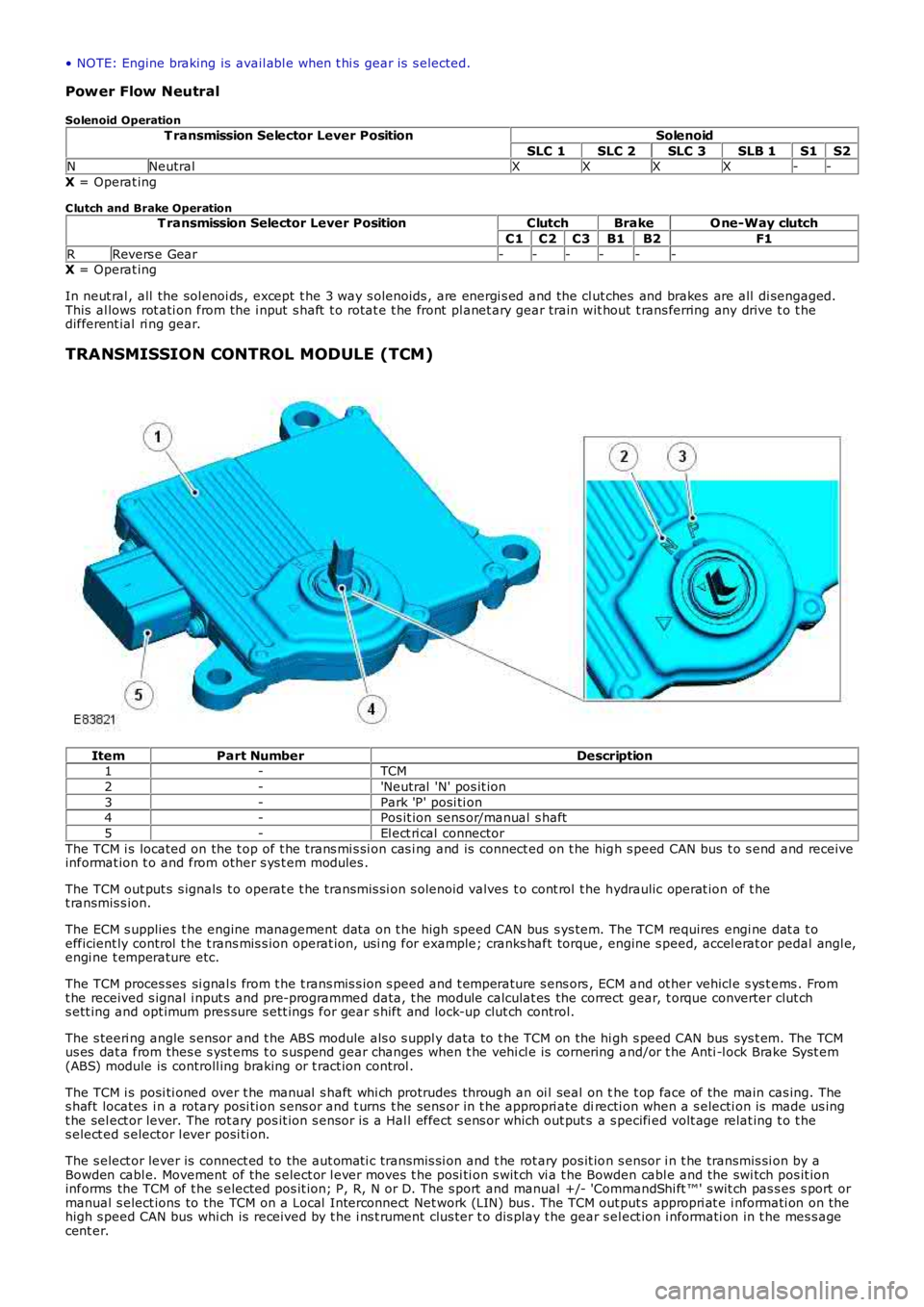
• NOTE: Engine braking is avail abl e when t hi s gear is s elected.
Power Flow Neutral
Solenoid Operation
T ransmission Selector Lever PositionSolenoid
SLC 1SLC 2SLC 3SLB 1S1S2NNeutralXXXX--
X = Operat ing
C lutch and Brake OperationT ransmission Selector Lever PositionClutchBrakeO ne-Way clutch
C1C2C3B1B2F1
RRevers e Gear------X = Operat ing
In neut ral , all the sol enoi ds , except t he 3 way s olenoids , are energi s ed and the cl ut ches and brakes are all di sengaged.This al lows rot ati on from the i nput s haft t o rotat e t he front pl anet ary gear train wit hout t rans ferring any drive t o t hedifferent ial ri ng gear.
TRANSMISSION CONTROL MODULE (TCM)
ItemPart NumberDescription1-TCM
2-'Neutral 'N' pos it ion
3-Park 'P' posi ti on4-Pos it ion sens or/manual s haft
5-El ect ri cal connector
The TCM i s located on the t op of t he trans mi s si on cas i ng and is connect ed on t he high s peed CAN bus t o s end and receiveinformat ion t o and from other s ys t em modules .
The TCM out put s s ignals t o operat e t he transmis si on s olenoid valves t o cont rol t he hydraulic operat ion of t het ransmis s ion.
The ECM s upplies t he engine management dat a on t he high speed CAN bus s ys tem. The TCM requires engi ne dat a t oefficient ly control t he t rans mis s ion operat ion, usi ng for example; cranks haft torque, engine s peed, accel erat or pedal angl e,engi ne t emperature etc.
The TCM proces ses si gnal s from t he t rans mis s ion s peed and t emperature s ens ors , ECM and ot her vehicl e s ys t ems . Fromt he received s ignal i nput s and pre-programmed data, t he module calculat es the correct gear, t orque converter clut chs ett ing and opt imum pres sure s ett ings for gear s hift and lock-up clut ch control.
The s teeri ng angle s ensor and t he ABS module als o s uppl y data to t he TCM on the hi gh s peed CAN bus sys t em. The TCMus es dat a from thes e s yst ems t o s us pend gear changes when t he vehi cl e is cornering and/or t he Anti -l ock Brake Syst em(ABS) module is controll ing braking or t ract ion control .
The TCM i s posi ti oned over t he manual s haft whi ch protrudes through an oi l seal on the t op face of the main cas ing. Thes haft locates i n a rotary posi ti on s ens or and t urns t he sens or in t he appropri ate directi on when a s electi on is made us ingt he sel ect or lever. The rot ary pos it ion s ens or i s a Hal l effect s ens or which out put s a s pecifi ed volt age relat ing t o t hes elect ed s elector l ever posi ti on.
The s elect or lever is connect ed to the aut omati c transmis si on and t he rot ary pos it ion s ensor i n t he transmis si on by aBowden cabl e. Movement of the s elect or l ever moves t he posi ti on s wit ch vi a t he Bowden cabl e and the swi tch pos it ioninforms the TCM of t he s elected pos it ion; P, R, N or D. The s port and manual +/- 'CommandShi ft ™' s wit ch pas s es s port ormanual s elect ions to the TCM on a Local Interconnect Net work (LIN) bus . The TCM out put s appropri at e i nformati on on thehigh s peed CAN bus whi ch is received by t he i ns t rument clus ter t o dis play t he gear sel ect ion i nformati on in t he mes s agecent er.
Page 1294 of 3229
W hen movi ng from a st andst il l, ups hi ft s can be pre-s el ect ed by making '+' s el ect ions wi th the s elect or l ever for thenumber of ups hifts requi red. The TCM t hen performs t he reques ted number of upshi ft s when appropri at e s hift points arereached. For exampl e; when moving off in 1s t gear, if 3 '+' s elect ions are made i n quick s ucces si on, t he TCM willautomat ically ups hift t hrough the gears to 4t h gear as t he vehi cl e accelerates , wit hout any furt her s electi ons bei ng made.
Cooling
Cooling mode is act ivated when t he TCM det ect s exces s ively hi gh trans mi s si on fl uid or engine coolant temperatures . W hent hi s mode i s act ive torque converter l ock-up is acti vat ed earl ier t o mi ni mi ze a further ris e in fl uid and/or engine coolantt emperature and ass i st flui d cool ing.
Hill Descent Control (HDC)
The HDC mode as s is t s t he ABS module i n cont rol li ng the downhil l speed of t he vehi cl e. W hen HDC i s acti ve, t he TCMs elect s t he mos t appropri at e gear for t he descent to maxi mi ze engi ne braking.
Maximum engi ne braking i s applied us i ng a s hift map which i nit iat es later ups hift s and earl y downshi ft s .
Cruise
W hen s peed cont rol i s act ivated, t he TCM receives a speed control acti ve mes s age on the hi gh s peed CAN bus . The TCMact ivat es a s peed cont rol map whi ch minimizes up and down s hifts .
Crui se mode is act ive when s peed cont rol is sel ect ed on and t he transmis s ion i s in drive 'D', s port 'S', HDC or Terrai nRespons e Gras s /gravel /s now program. Unique cruis e maps overri de the current mode t o provide a smoot h driving feel andmode resel ect ion.
Limp Home
If a transmis s ion faul t is det ect ed by t he TCM, the TCM adopt s a l imp home s trategy and a mes s age 'TRANSMISSIONFAULT LIMITED GEARS AVAILABLE' i s dis played in the mes s age cent er. If the fault has an effect on engi ne emis s ions , theMIL in the i nst rument clus t er wi ll als o be il luminat ed.
In li mp home mode, P, R and N functi ons operate normall y (i f the fault al lows t hes e s elect ions) and t he TCM locks t het ransmis s ion i n 3rd gear t o all ow t he dri ver t o t ake the vehicle to a Land Rover deal er or approved repai rer. Torqueconvert er lock-up i s dis abled and reverse-lock-out wil l not funct ion.
If the vehicle is s t opped and s ubsequentl y res tarted in t he li mp home mode condi ti on, t he TCM operat es normall y unti l thefaul t which caus ed t he condi ti on is det ect ed agai n.
Coast
Coast mode provides earli er downs hifts during coast ing dependant on out put shaft decelerat ion rate to improve driveabili tyand refinement by avoi ding negati ve to pos it ive driveli ne torque revers als t rans mi ssion during t he downshi ft s .
Fast Off Recognition
Fast off recogni ti on is act ivated when t he TCM det ect s t hat t he dri ver has releas ed the accel erat or pedal qui ckl y. This isdetected by the TCM monit oring for a high level of negat ive pedal angl e from ECM s ignals on t he high speed CAN bus . Ift hi s condi ti on is det ect ed, t he TCM hol ds the current gear rati o to allow the driver t o compl ete the manoeuvre wi thout t heneed for a downs hift. The mode can remain acti ve for a predet ermined lengt h of ti me or i f the driving s t yl e remainspass i ve.
Fast off recogni ti on mode as si s ts vehicle st abili ty and is us ed i n conjunct ion a lateral accel erat ion i nput duri ng corneri ng tomaint ain t he current gear unti l the corner is negot iated.
Uphill and Trailer
Uphill and t rai ler mode can be acti ve when the trans mi s si on is operat ing in normal, s port or Terrai n Res pons e modes .W hen t he vehicle i s pull ing a t rai ler or dri vi ng up an i ncl ine, the TCM det ects t he i ncreas ed res i st ance by monit oring enginet orque and s peed s i gnal s received from the ECM on the hi gh s peed CAN bus and als o t rans mis s ion out put s haft s peeds ens or s ignals . Uphi ll and t rai ler mode wi ll provide downs hift s t o prevent a drop in t rans mi ss i on torque out put andmaint ain driving force.
Downhill
Downhill mode can be act ive when t he t ransmis s ion i s operati ng in normal, s port or Terrain Res pons e modes . W hen t hevehi cl e i s descendi ng an i ncl ine t he TCM detect s a reducti on in res is t ance by moni toring engine t orque and s peed si gnal sreceived from the ECM on t he high s peed CAN bus and als o t rans mis s ion out put shaft speed s ensor s ignals . Downhill modeas si st s engine braki ng by s elect ing an appropriat e gear reduci ng the load required on t he brakes .
Wide Throttle
W i de open thrott le mode operates for part thrott le ups hifts and ki ck-down ups hifts . It provides cons i st ent wide opent hrott le ups hift performance under all driving condit ions. The full engine s peed range is used i n all driving modes ; normal ,s port, hi ll modes and Commands hi ft . Compens at ion i s used for delays (hydrauli c and electroni c) in gear change reques t togear change s tart to provi de s mooth changes and correct shi ft point correct ion.
Terrain Response
The Terrai n Res pons e s ys tem has a unique s et of shi ft maps for each of t he Terrai n Res pons e programs . Thes e programsoverri de exis ti ng modes; for exampl e when HDC is acti ve and the 'Sand', 'Mud and Ruts ' or 'Grass /Gravel/Snow' programsare sel ect ed, a specific Terrain Res ponse map is used, not the HDC mode s hift map detai led previ ous ly.
Page 1295 of 3229
Reverse Lock-Out
If the s elector l ever is moved from N to R and t he vehi cl e i s travel li ng forwards , revers e s electi on is prevent ed if t hevehi cl e s peed is 11 km/h (6.8 mph) or more. W hen revers e lock-out is act ivated, t he cl utch (C3) is released wit houtenergizing sol enoid (SLC3), preventi ng t he transmis si on from sel ect ing reverse gear.
TRANSMISSION FAULT STATUS
If the TCM det ect s a fault wi th the t rans mi ss ion sys tem, it wi ll enter a defaul t (l imp home) mode to prevent furt herdamage to the trans mi ss i on and allow the vehicl e to be dri ven. If pos s ibl e revers e gear wil l be avai lable and al s o 3rd gearonly.
W hen a fault i s detected a high s peed CAN mes s age is s ent from the TCM and is recei ved by the i nst rument clus ter. Theins t rument clus ter il lumi nat es t he MIL (i f required) and di spl ays an appl icabl e mes sage in t he mes s age cent er.For addit ional informat ion, refer t o: Informat ion and Mes s age Cent er (413-08 Informat ion and Mes s age Cent er, Des cript ionand Operat ion).
Some t rans mis s ion fault s may not il lumi nat e t he MIL or dis play a fault mes s age, but t he driver may not ice a reduct ion i ns hift quali ty.
ENGINE SPEED AND TORQUE MONITORING
The ECM const antl y s uppl ies t he TCM wi th informati on on engine s peed and torque through mes s ages on the CAN bus. TheTCM us es t hi s informat ion t o calculat e the correct and appropriat e t imi ng of shi ft changes .
If the mes s ages are not received by t he ECM, the TCM wil l impl ement a back-up st rat egy to prot ect t he transmis s ion fromdamage and all ow t he vehi cl e t o be dri ven.
In the event of an engi ne s peed or t orque s i gnal fai lure, t he t rans mis s ion wi ll adopt the el ect ri cal li mp home mode wit ht he trans mi s si on operati ng in a fixed gear.
TOWING FOR RECOVERY
W ARNING: Ens ure that t he remot e hands et remains docked whi ls t the vehicl e is bei ng towed. Removing t he remot ehands et wil l engage t he s teering l ock, which wi ll prevent the vehicle from s t eering correct ly.
If the engine cannot be run whi ls t the vehicl e is bei ng towed, t here wi ll be no power ass i st ance for the st eeri ng or brakes .This wi ll res ult in great er effort being requi red t o s t eer or s low the vehicle, and great ly i ncreas ed s t oppi ng dis tances.
CAUTION: The vehicle s hould only be towed wit h four wheels on the ground. Towing wi th two wheel s on t he groundwil l res ult i n s erious damage t o t he t ransmis s ion.
The vehi cl e s houl d only be towed for a maximum of 80 km (50 miles ), at a maximum s peed of 80 km/h (50 mph). Towi ngfor a greater dis t ance, or at a higher speed may res ul t in serious damage t o t he trans mi s si on.
• NOTE: The recommended recovery met hod is by trailer or recovery vehicle.
Secure t he towi ng att achment from the recovery vehicl e to the front t owing eye.
Ins ert the remote hands et in t he s tart cont rol module and swi tch on the i gni ti on by pres s ing t he s tart/s top but ton once.
• NOTE: Leavi ng the ignit ion s wit ched on for extended peri ods will cause the bat tery t o drain.
Apply t he foot brake, and move t he s el ect or lever to the neutral 'N' pos i ti on. W it h t he foot brake s ti ll appl ied, rel eas e t hepark brake. If elect rical power t o the sel ect or is not avai lable, t he emergency releas e l ever on t he s elect or lever can beus ed to releas e t he int erlock s olenoid.
The vehi cl e can be t owed a maximum of 80 km (50 mil es ) at a maxi mum speed of 80 km/h (50 mph).
Park t he vehicle on firm, l evel ground. Appl y the park brake and move t he s elector lever t o the park 'P' posi ti on.
Swit ch off t he ignit ion and remove t he remot e handset .
CAUTION: The vehicle cannot be towed i n a revers e direct ion.