2006 LAND ROVER FRELANDER 2 headlamp
[x] Cancel search: headlampPage 186 of 3229
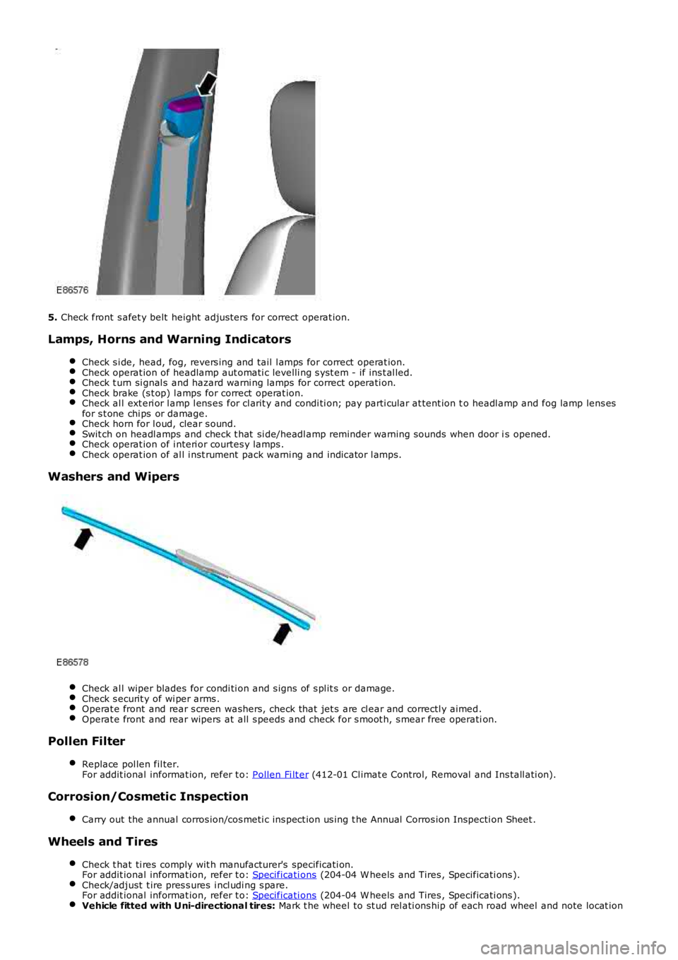
5.
Check front s afet y belt height adjus ters for correct operat ion.
Lamps, Horns and Warning Indicators Check s i de, head, fog, revers ing and tail l amps for correct operat ion. Check operat ion of headlamp aut omati c levelli ng s yst em - if ins t al led.
Check t urn si gnal s and hazard warni ng lamps for correct operati on.
Check brake (s t op) l amps for correct operat ion.
Check al l ext eri or l amp l ens es for cl arit y and condi ti on; pay parti cular at tent ion t
o headl amp and fog lamp lens es
for s t one chi ps or damage. Check horn for l oud, clear s ound.
Swit ch on headl amps and check t hat si de/headl amp reminder warning s ounds when door i
s opened.Check operat ion of i nteri or courtes y lamps .
Check operat ion of al l i nst rument pack warni ng and indicator l amps.
Washers and Wipers
Check al l wiper blades for condi ti on and s igns of s pl it s or damage.
Check s ecurit y of wi per arms .
Operat e front and rear s creen washers, check that jet s are cl ear and correctl y aimed
.Operat e front and rear wipers at all s peeds and check for s moot h, s mear free operati
on.Pollen Filter
Replace pol len fil ter.
For addit ional informat ion, refer t o: Pollen Fi lt er (412-01 Cl imat e Control, Removal and Ins tall ati on).
Corrosion/Cosmetic Inspection
Carry out the annual corros ion/cos meti c ins pect ion us ing t he Annual Corros ion Inspec ti on Sheet .Wheels and Tires
Check t hat ti res comply wit h manufacturer's specificati on.
For addit ional informat ion, refer t o: Specificati ons (204-04 W heels and Tires , Specificati ons ).
Check/adjust t ire pres s ures i ncl udi ng s pare.
For addit ional informat ion, refer t o: Specificati ons (204-04 W heels and Tires , Specificati ons ).
Vehicle fitted with Uni-directional tires:
Mark t he wheel to st ud rel ati ons hip of each road wheel and note locat ion
Page 291 of 3229
Publi s hed: 11-May-2011
Vehicle Dynamic Suspension - Rear Suspension Height Sensor
Removal and Inst all ati on
Removal
• NOTE: This s ens or i s only fit ted to vehicles wit h Xenon headlamps and is i nst all ed on the LH s ide of t he vehi cl e.
• NOTE: Removal s t eps in t his procedure may cont ain i nst all ati on det ail s.
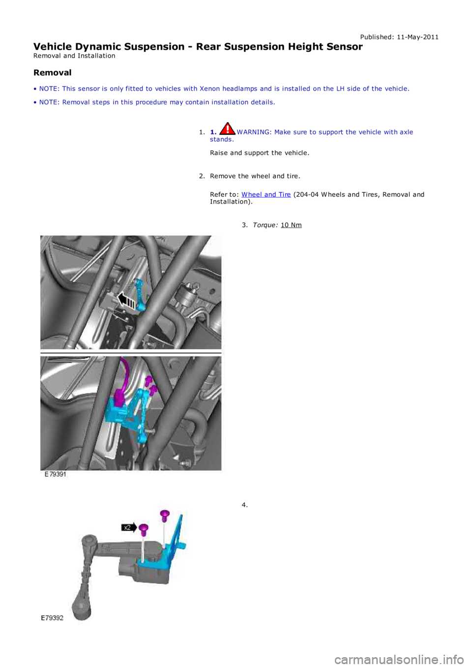
1. W ARNING: Make sure t o s upport the vehicle wit h axle
s tands .
Rais e and s upport t he vehi cl e.
1.
Remove t he wheel and t ire.
Refer t o: W heel and Ti re (204-04 W heel s and Tires, Removal and
Inst all at ion).
2. T orque:
10 Nm 3.
4.
Page 561 of 3229
Publi s hed: 11-May-2011
Power Steering - Power Steering Fluid Cooler
Removal and Inst all ati on
Removal
1. W ARNING: Do not work on or under a vehi cle s upported onl yby a jack. Al ways support t he vehi cl e on s afet y s tands .
Rais e and s upport t he vehi cl e.
1.
Remove t he front wheel s and ti res .
Refer t o: W heel and Ti re (204-04 W heel s and Tires, Removal andInst all at ion).
2.
Remove t he front bumper.
Refer t o: Front Bumper (501-19 Bumpers , Removal and Ins tall ati on).
3.
Remove t he RH headlamp as s embly.
Refer t o: Headl amp As sembl y (417-01 Ext eri or Li ght ing, Removaland Inst all at ion).
4.
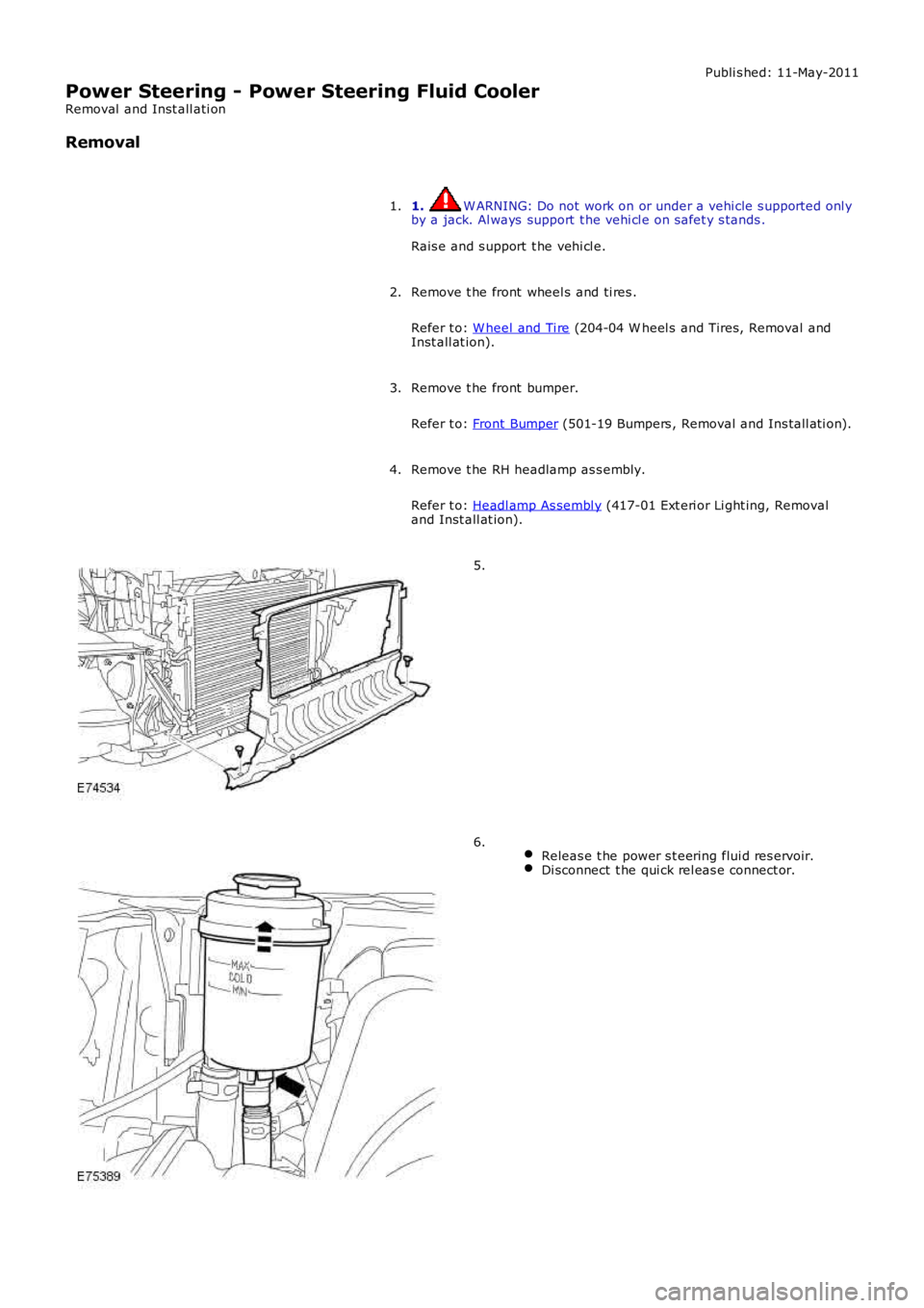
5.
Releas e t he power s t eering flui d res ervoir.Di sconnect t he qui ck rel eas e connect or.
6.
Page 587 of 3229
11-Int egrated audio modul e
12-Int egrated control modul e
PRINCIPLES OF OPERATION
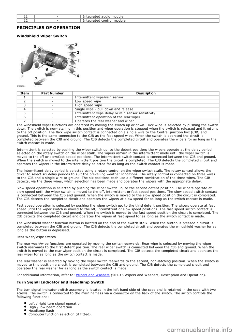
Windshield Wiper Switch
ItemPart NumberDescription
1-Intermit tent wi pe/rai n s ens or
2-Low s peed wipe3-Hi gh s peed wi pe
4-Singl e wipe - pul l down and releas e
5-Intermit tent wi pe del ay or rai n s ens or s ens it ivi ty6-Intermit tent operat ion of t he rear wiper
7-Operat es t he rear was her and wi per
The winds hield wiper functi ons are operat ed by moving t he s wit ch up or down. Fl ick wi pe is s elected by pus hing the s wi tchdown. The swi tch i s non-l at chi ng in thi s posi ti on and wiper operati on is st opped when the swi tch i s rel eas ed and i t ret urnst o the off posi ti on. The fli ck wipe s wi tch contact is connect ed on a s ingl e wire t o t he Cent ral junct ion box (CJB) andground. Thi s is the s ame connect ion t o t he CJB as t he fas t s peed wipe. W hen t he s witch is operat ed t he ci rcuit i scompleted bet ween the CJB and ground. The CJB detects the complet ed circui t and operat es t he wipers for as l ong as thes wit ch cont act i s made.
Int ermit tent is sel ect ed by pushi ng the wiper swi tch up, t o t he det ent pos i ti on; t he wi pers operate at the del ay periods elect ed on t he rot ary swi tch on the wi per st alk. The wipers remai n in the i ntermit tent mode unt il t he wiper s wit ch ismoved t o the off or s low/fas t speed pos it ions. The i ntermit tent s wit ch cont act is connected bet ween t he CJB and ground.W hen t he s wit ch is moved to the i ntermit tent posi ti on t he ci rcuit i s completed. The CJB detects the complet ed circuit andoperates t he wi pers i n the intermit t ent delay sel ect ed for as l ong as the s wi tch contact is made.
The int ermi tt ent del ay period is s elected us i ng a rot ary control on the wiper s wit ch st alk. The rot ary control al lows t hedri ver t o s elect s ix delay periods to s ui t the prevai li ng weather condit ions . The rot ary control i s connected on three wirest o the CJB and a s ingle wire to ground. The s i x pos i ti ons each us e a di fferent combinat ion of t he t hree wi res . The CJBdetects , via the t hree wi res , which s electi on has been made and operates t he wi pers wi th the appropri ate del ay.
Slow speed operat ion i s s el ect ed by pus hi ng t he wiper s wit ch up, t o t he s econd det ent pos it ion. The wipers operate ats low speed unti l the wiper swi tch i s moved t o t he off, intermit t ent or fast s peed posi ti ons . The s low s peed s wi tch contactis connect ed between t he CJB and ground. W hen t he s wit ch is moved t o t he s low speed pos it ion t he circuit is complet ed.The CJB detects t he complet ed ci rcuit and operat es the wipers at s l ow s peed for as long as the s wi tch cont act is made.
Fast s peed operati on is sel ect ed by pushi ng the wiper swit ch up, t o t he thi rd det ent pos it ion. The wi pers operate at fas ts peed unt il t he wiper s wit ch is moved to t he off, int ermi tt ent or sl ow s peed pos i ti ons . The fas t s peed s wit ch cont act i sconnected bet ween the CJB and ground. W hen t he s wit ch is moved to the fast speed posit ion t he circuit i s complet ed. TheCJB detects t he complet ed ci rcuit and operat es the wipers at fas t speed for as long as t he s wit ch cont act i s made.
The winds hield washer functi on butt on is locat ed on t he end of t he swit ch st alk. W hen t he butt on is pres sed a circuit i scompleted bet ween the CJB and ground. The CJB detects the complet ed circui t and operat es t he winds hield washer for aslong as t he butt on i s depress ed.
Rear W as h/W i pe Swit ch
The rear was h/wi pe functi ons are operat ed by moving t he s wit ch rearwards . Rear wi pe is sel ect ed by moving t he wi pers wit ch rearwards t o the fi rs t detent posi ti on. The rear wiper swit ch is connected bet ween t he CJB and ground. W hen thes wit ch is moved t o t he rear wi per pos it ion t he circui t is complet ed. The CJB det ect s t he compl eted circui t and operates t herear wi per for as long as t he s wit ch cont act i s made.
The rear was her i s s elected by movi ng the wiper s wit ch rearwards to the s econd, non-l atching pos it ion. W hen t he s wit ch ismoved t o thi s posi ti on a circui t is compl et ed between t he CJB and ground. The CJB det ect s t he completed ci rcuit andoperates t he rear was her for as l ong as the s wi tch contact is made.
For addit ional informat ion, refer t o: W i pers and W as hers (501-16 W ipers and W as hers , Des cri pti on and Operati on).
Turn Signal Indicator and Headlamp Switch
The t urn s ignal indicator s wit ch as sembl y is locat ed i n the left hand s ide of t he case and is retai ned in t he case wit h t wos crews . The swi tch i s connected t o t he mai n harnes s via a connect or on the back of the s wit ch. The s wit ch cont rol s thefol lowing funct ions :
Left / right turn s ignal operati onHigh / low beam operati onHeadl amp flas hComputer functi on s electi on (i f fi tt ed).
Page 588 of 3229
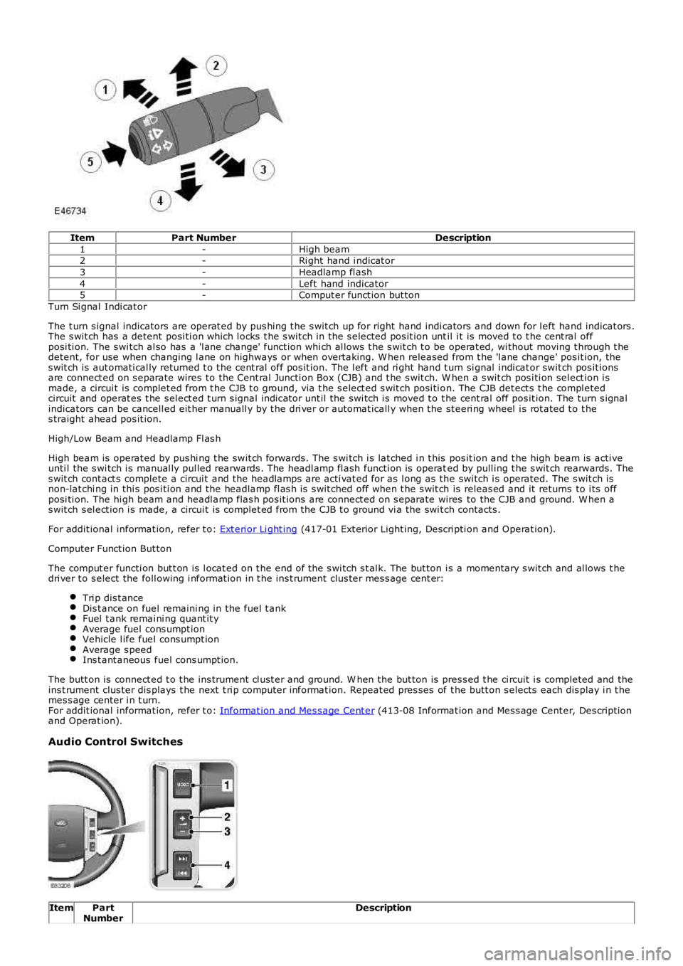
ItemPart NumberDescription
1-High beam2-Ri ght hand i ndicat or
3-Headlamp fl ash
4-Left hand indicator5-Comput er funct ion but ton
Turn Si gnal Indi cat or
The t urn s ignal indicators are operat ed by pus hing t he s wit ch up for right hand indicators and down for l eft hand indicat ors .The s wit ch has a detent posi ti on which l ocks t he s wit ch in the s elected pos it ion until i t is moved t o t he cent ral offposi ti on. The s wi tch al so has a 'l ane change' funct ion whi ch al lows t he s wit ch t o be operat ed, wi thout moving t hrough t hedetent, for use when changing l ane on highways or when overtaking. W hen released from t he 'l ane change' pos it ion, thes wit ch is aut omati cal ly returned t o t he cent ral off pos it ion. The l eft and ri ght hand t urn si gnal i ndi cat or swit ch pos it ionsare connect ed on s eparate wires to the Cent ral Juncti on Box (CJB) and t he s wit ch. W hen a s wit ch pos i ti on sel ect ion i smade, a circui t is complet ed from t he CJB t o ground, vi a t he s elect ed s wit ch posi ti on. The CJB det ect s t he compl etedcircuit and operat es t he s el ect ed t urn s ignal indicator unt il the swi tch i s moved t o t he cent ral off pos it ion. The turn s ignalindicat ors can be cancell ed eit her manuall y by t he dri ver or automat icall y when t he st eeri ng wheel i s rot ated t o t hes traight ahead pos it ion.
High/Low Beam and Headlamp Fl as h
High beam is operat ed by pus hi ng t he swit ch forwards. The s wi tch i s lat ched i n t his pos it ion and t he high beam is acti veunti l the s wi tch i s manual ly pul led rearwards . The headl amp fl ash functi on is operated by pull ing t he s wit ch rearwards. Thes wit ch cont act s complete a circui t and the headlamps are acti vat ed for as l ong as the swi tch i s operated. The s wit ch isnon-lat chi ng in thi s pos i ti on and the headlamp fl as h is s wit ched off when t he s wit ch is releas ed and it returns to i ts offposi ti on. The hi gh beam and headl amp flas h pos it ions are connect ed on s eparate wires to the CJB and ground. W hen as wit ch s el ect ion i s made, a circui t is complet ed from the CJB t o ground vi a the swi tch contacts .
For addit ional informat ion, refer t o: Ext eri or Li ght ing (417-01 Ext erior Light ing, Descri pti on and Operat ion).
Computer Funct ion But ton
The comput er functi on but t on is l ocat ed on t he end of the s wi tch s t al k. The but ton is a momentary s wit ch and al lows t hedri ver t o s elect the foll owing i nformat ion in t he ins t rument clus ter mes s age cent er:
Tri p dis t anceDis t ance on fuel remaini ng in the fuel t ankFuel t ank remai ni ng quant it yAverage fuel cons umpt ionVehicle l ife fuel cons umpt ionAverage s peedIns t ant aneous fuel cons umpt ion.
The butt on is connect ed t o t he ins trument cl ust er and ground. W hen the but ton is pres s ed t he ci rcuit i s completed and theins t rument clus ter dis plays t he next t ri p computer informat ion. Repeat ed pres ses of t he butt on s elects each dis play i n t hemes s age center i n t urn.For addit ional informat ion, refer t o: Informat ion and Mes s age Cent er (413-08 Informat ion and Mes s age Cent er, Des cript ionand Operat ion).
Audio Control Switches
ItemPartNumberDescription
Page 1771 of 3229
Vehicle i n power mode 6 (all vehi cles except NAS vehicles )Vehicle i n power mode 6 for 75 s econds (NAS vehicl es onl y)Vehicle s peed is greater t han 6 mph (10 kph)Dri vers s afet y belt not s ecured in i ts buckleLarge pas senger det ect ed i n front pas s enger s eat wit h an uns ecured safety bel t.
The warni ng indicator wi ll flas h at a frequency of 2 Hz while accompani ed by a chime from the i nst rument clus ter for 10s econds. Thi s is foll owed by a 10 s econd period where the warning i ndicat or is permanent ly ill uminat ed and the s ounder i ss il ent . Thi s 10 s econd cycle wi ll be repeat ed for a maxi mum of 190 seconds or any of t he condit ions l is t ed above cease toexis t.
Supplemental Restraint System Warning Indicator
The Suppl ement al Rest rai nt Sys tem (SRS) warning i ndi cat or is i lluminated on recei pt of a medium s peed CAN bus si gnalfrom the CJB. The si gnal originat es in t he RCM whi ch monit ors t he condi ti on of the SRS and ill uminat es the red warni ngindicat or accordingly.
The SRS warni ng indicator i s il lumi nat ed by t he RCM for a 6 s econd bul b check when the vehicle firs t ent ers power mode 6.If a fault is detect ed wit h t he indicator, the ins trument cl us t er returns a medi um speed CAN bus s ignal vi a t he CJB to theRCM and a Diagnos t ic Troubl e Code (DTC) i s s tored in the RCM's memory. The mes s age 'SrS' wi ll als o be di spl ayed i n t heodometer.For addit ional informat ion, refer t o: Informat ion and Mes s age Cent er (413-08 Informat ion and Mes s age Cent er, Des cript ionand Operat ion).
Left and Right Hand Turn Signal Indicators
The green l eft and right hand turn s ignal i ndicat ors are i ll uminated on recei pt of medium speed CAN bus s i gnals from t heCJB. The CJB provi des a CAN bus s ignal wit h one of t he foll owing values :
0 - LH st eeri ng col umn mul ti -funct ion s wit ch in the central pos it ion1 - LH st eeri ng col umn mul ti -funct ion s wit ch in the LH turn posi ti on2 - LH st eeri ng col umn mul ti -funct ion s wit ch in the RH turn pos it ion3 - Hazard fl as hers reques t ed.
If the vehicle is i n power mode 6 t he ins trument cl ust er wil l fl as h the appropri ate turn s ignal i ndicat or if a medium speedCAN bus s ignal is recei ved wit h a value of 1 or 2. Medi um s peed CAN bus s ignals wi th a value of 3 wi ll acti vat e both theLH and RH turn s ignal i ndicat ors si mult aneous ly i rrespecti ve of power mode.
W hen acti vat ed, the l eft and right hand turn s ignal indicators wil l be accompanied by 'ti ck t ock' chimes from t he ins trumentclus ter s ounder.
Brake Warning Indicator
EBA and EBD warnings are trans mi tt ed t o t he CJB from t he ABS module over t he high s peed CAN bus . Thes e s ignals arerel ayed t o t he i ns t rument clus ter on t he medium s peed CAN bus and wil l act ivate the brake warning i ndicat or when t hevehi cl e i s in power mode 6. If an EBA warni ng is request ed, the i ndi cat or wil l ill uminat e in an amber color. If an EBDwarni ng is reques t ed, t he indi cat or will i ll uminate in a red color.
Low brake flui d level warnings are als o t rans mit t ed to the i nst rument clus t er from the CJB on the medi um s peed CAN bus .The s ignal origi nat es in the ABS modul e which recei ves a hardwired input from the brake flui d level s ens or. If a l ow brakefl uid warning i s reques ted, the indicator wil l il lumi nat e i n a red col or when the vehicle is i n power mode 6.
The brake warni ng indi cat or i s als o s ubject t o a 3 second bul b check when the vehicle firs t ent ers power mode 6. Theindicat or wi ll i lluminate in a amber color for 1.5 s econds t hen a red col or for 1.5 s econds .
High Eng ine Coolant Temperature Warning Ind icator
The red hi gh Engine Coolant Temperature (ECT) warning i ndi cat or is control led by the engine t emperat ure gage s oft ware(see above).
Headlamp High Beam Indicator
The blue headlamp hi gh beam i ndi cat or is i ll uminated on recei pt of a medium s peed CAN bus si gnal from the CJB. Thes ignal origi nat es in the l ight s wit ch module and i s t ransmit ted t o t he CJB over t he LIN bus. The i nst rument clus t er will onlyil lumi nat e t he headl amp high beam indicator when t he vehicle i s in power mode 6 and t he LH s teeri ng column mul ti -functi on s wit ch is moved t o t he high beam pos i ti on.
Tire Pressure Monitoring System Indicator
The Tire Pres s ure Moni tori ng Syst em (TPMS) indicator i s cont rol led by t he ins t rument clus ter on receipt of medium s peedCAN bus s ignals from t he CJB. The s ignal ori gi nates i n t he TPMS module. The indicator i s il lumi nat ed in an amber col or fora 3 second bulb check by the TPMS modul e when t he vehi cl e enters power mode 6. If t he indicator remains i lluminated orfl ashes after t he engi ne is st art ed or when dri vi ng, the TPMS has developed a faul t. The t ire pres s ures s houl d bemonit ored manuall y unti l the fault is recti fi ed.For addit ional informat ion, refer t o: W heels and Ti res (204-04 W heels and Tires , Des cript ion and Operat ion).
Anti-lock Brake System Warning Indicator
The Anti -l ock Brake Sys t em (ABS) warning i ndicat or is controll ed by the ABS module whi ch trans mi ts a high s peed CAN busmes s age to t he CJB. The CJB relays t he mes sage t o t he i ns t rument clus ter over the medi um s peed CAN bus . The warningindicat or i s il lumi nat ed i n an amber col or for 3 s econds for a bulb check by the ABS modul e when t he vehi cl e enters powermode 6. If the warning i ndi cat or remains ill uminat ed or ill uminat es when drivi ng, an ABS fault has occurred and t he ABSfuncti on wil l not be avai lable.
Duri ng the bul b check, if t he warni ng indicator comes on for 0.5 s econd, t hen goes off for 0.5 second and is then
Page 1821 of 3229
APPENDIX A BATTERY TEST PROCESS
It is recommended t hat this tes t is conduct ed at leas t 24 hours after t he vehi cl e engine has been run or t he batt erycharged to avoi d the need of s urface charge removal or i f thi s t ime cons traint is unaccept abl e due t o circums t ances , thenconduct the charge s t ri p removal process .
Part 1 - Surface Charge Removal
• NOTE: Before carryi ng out a batt ery t est you must ens ure t hat there is no bat t ery s urface charge present .
• NOTE: The batt ery may be t es t ed eit her on a bench or on t he vehicle.
In the cas e of on-vehicle tes ti ng, t he batt ery must be is olated from t he vehi cl e by removal of t he bat t ery negati ve(-) cable from the bat tery t ermi nal before t he measurement is t aken unl ess the vehicle has a transi t rel ay fi tt ed oris in t rans it mode.
A vehicle which has had it s batt ery charged or been dri ven in a 24 hour period before t he tes t , must have i ts s urfacecharge removed us ing one of t he fol lowi ng methods :
1. If 24 hours have pas s ed s ince the las t ti me t he engine was run or the bat tery charged, proceed t o `Part 2 - Bat teryTest '.
2. Turn on t he i gni ti on. Swi tch on t he headlamps on hi gh beam for a mini mum 3 minut es .
3. Swit ch off t he headl amps . For vehi cl es tes t ed aft er t he t rans it relay has been removed, di s connect t he batt ery byremoval of the negati ve (-) cabl e. Vehi cl es wit h a trans i t relay fit t ed or wit h a l ow current t rans port mode enabled do notneed to have t he batt ery di s connect ed.
4. W ait a maximum of 5 mi nut es before recordi ng tes t res ult s for any bat tery measurements .
Part 2 - Battery Test
• NOTE: The batt ery s urface charge mus t be removed before t his t est i n accordance with the procedure in Part 1 above.Ensure t hat t he batt ery terminal connect ors are clean. W hen connecti ng t he Midt ronics t est ing equipment , connect the REDclip to the pos it ive (+) batt ery terminal fi rs t, and t hen connect the BLACK cl ip t o t he negat ive (-) bat tery t ermi nal . Rockt he cl ips backward and forward to ens ure a good connecti on to the bat tery.
• NOTE: Mi dt roni cs 393, 394. 493 and 494 t es ters mus t not be us ed t o t est AGM batt eri es as thes e t est ers are not capableof correctl y t es t ing AGM batt eries and can gi ve an incorrect resul t. For AGM batt ery tes ti ng us e the EXP1080 t es t er or t heGR1 Di agnos ti cs charger.
CAUTION: DO NOT connect t he t es t er to any ot her ci rcuit or chas s is poi nt ot her than t he batt ery negati ve terminal.
1. Att ach the Midtronics tes t er t o t he batt ery.
2. Fol low the i nst ruct ions on t he tes t er t o t est the bat tery. Ens ure t he correct batt ery type and s ize i s s elect ed.
3. Perform the acti on based on the t es ter res ult s (s ee table bel ow).
4. Ent er the readings and t es t code obtained on the Bat tery Report Form (Appendi x B) or equi val ent whi ch records as ami ni mum the t echni ci an's name, Vehi cl e Ident ificati on Number (VIN), Dat e of check, Midtronics code and Bat t ery Volt agefrom the Mi dtroni cs tes ter.
At t he end of the t est , t he bat t ery negati ve (-) cabl e s houl d be re-att ached to t he batt ery terminal.
T EST ER RESULT SACT ION
GOOD BATTERYReturn t o s ervice.
GOOD RE-CHARGEFully charge bat tery and ret urn to servi ce.CHARGE AND RE-TESTFully charge bat tery. Remove s urface charge. Re-tes t batt ery. If s ame res ult repl ace bat tery.
REPLACE BATTERY OR BADCELL BATTERYVeri fy s urface charge removed. Dis connect bat tery from vehicle and re-tes t. If res ult repeat saft er surface charge removal , replace batt ery. DO NOT RECHARGE.
UNABLE TO DO TESTDis connect batt ery from vehi cl e and re-t es t .
APPENDIX B : BATTERY REPORT FORM - IN SERVICE BATTERIES ONLY
• NOTE: Fields marked wi th * are mandat ory and mus t be complet ed.
General InformationYES /NO YES /NO
Cus tomer Name: Dealer/Retai ler Code:*
Repair Order Number:*Batt ery Dat e Code:* Repair Order Dat e:*Number of Ti mes Bat teryCharged:*
Repair Order Dat e: Technici ans Name:*
Vehicle Identi fi cat ion Number (VIN):*Technici ans Si gnat ure:*
Gi ve a detail ed descripti on of the sympt oms experienced by the cus tomer (att ach a s eparate sheet if necess ary)-
-
--
-
-
Page 1833 of 3229
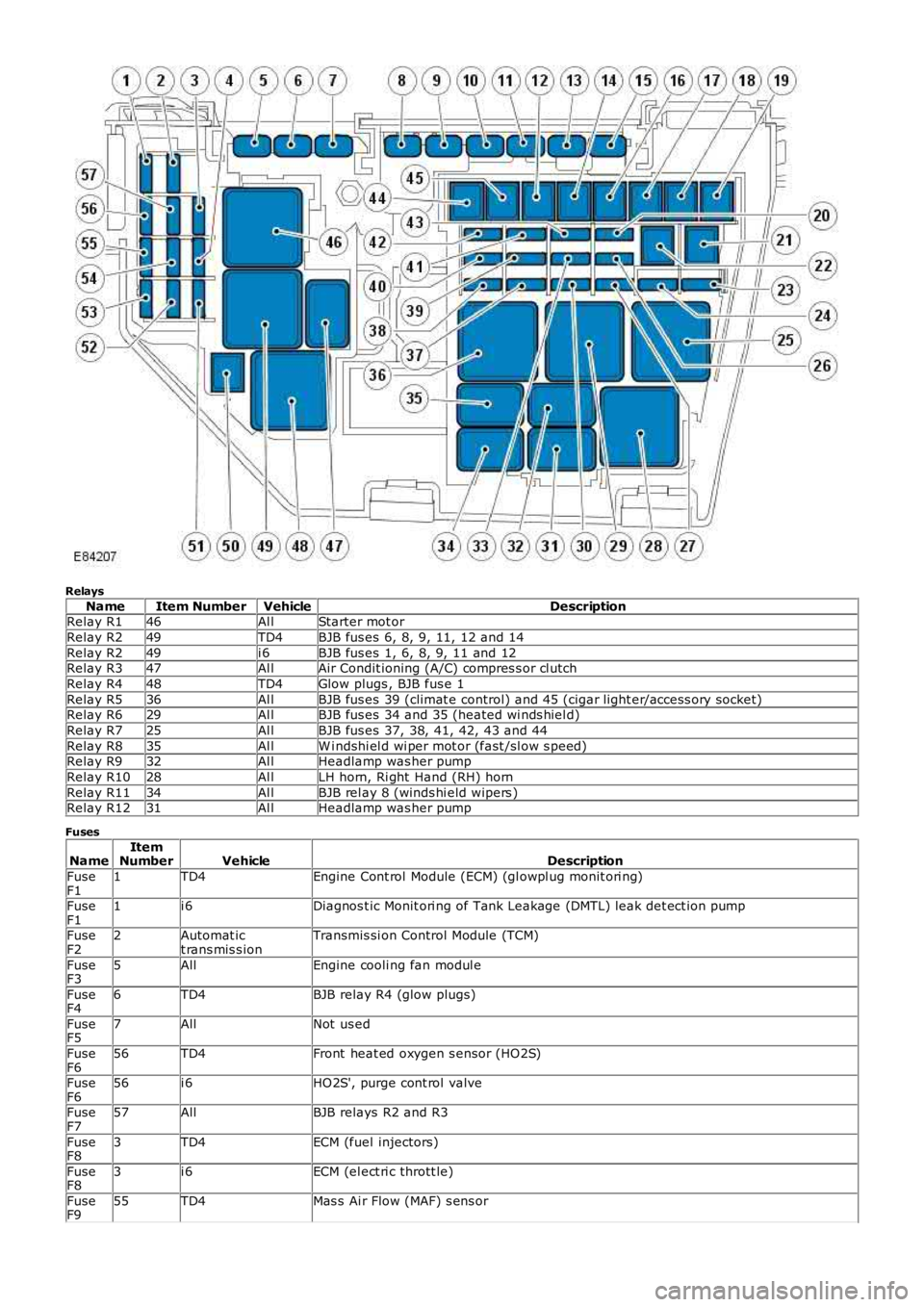
Relays
NameItem NumberVehicleDescriptionRelay R146Al lStarter mot or
Relay R249TD4BJB fus es 6, 8, 9, 11, 12 and 14
Relay R249i 6BJB fus es 1, 6, 8, 9, 11 and 12Relay R347Al lAir Condit ioning (A/C) compres s or cl utch
Relay R448TD4Glow plugs , BJB fus e 1
Relay R536Al lBJB fus es 39 (climat e control) and 45 (cigar light er/access ory socket)Relay R629Al lBJB fus es 34 and 35 (heated wi nds hiel d)
Relay R725Al lBJB fus es 37, 38, 41, 42, 43 and 44
Relay R835Al lW i ndshi el d wi per mot or (fast /sl ow s peed)Relay R932Al lHeadlamp was her pump
Relay R1028Al lLH horn, Ri ght Hand (RH) horn
Relay R1134Al lBJB rel ay 8 (winds hi eld wipers )Relay R1231Al lHeadlamp was her pump
Fuses
NameItemNumberVehicleDescription
FuseF11TD4Engine Cont rol Module (ECM) (gl owpl ug monit ori ng)
FuseF11i 6Diagnos t ic Monit ori ng of Tank Leakage (DMTL) leak det ect ion pump
FuseF22Automat ict rans mis s ionTransmis si on Control Module (TCM)
FuseF35AllEngine cooli ng fan modul e
FuseF46TD4BJB relay R4 (glow plugs)
FuseF57AllNot us ed
FuseF656TD4Front heat ed oxygen s ensor (HO2S)
FuseF656i 6HO2S', purge cont rol valve
FuseF757AllBJB relays R2 and R3
FuseF83TD4ECM (fuel injectors)
FuseF83i 6ECM (el ect ri c thrott le)
FuseF955TD4Mas s Ai r Flow (MAF) s ens or