2006 LAND ROVER FRELANDER 2 check oil
[x] Cancel search: check oilPage 328 of 3229
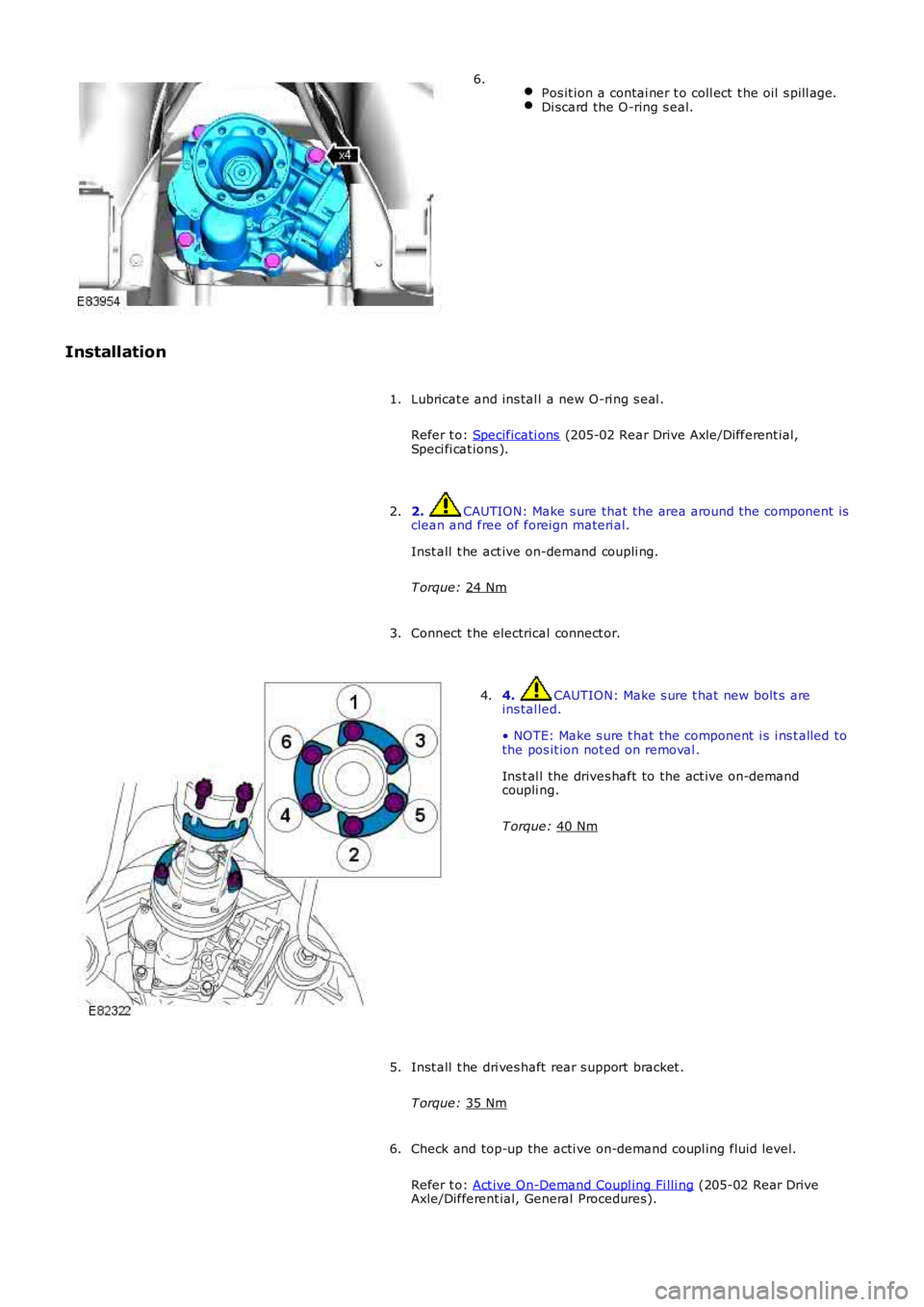
Pos it ion a contai ner t o coll ect t he oil s pill age. Di scard the O-ring s eal.6.
Installation Lubricat e and ins tal l a new O-ri ng s eal .
Refer t o: Specificati ons (205-02 Rear Drive Axle/Different ial,
Speci fi cat ions ).
1.
2. CAUTION: Make s ure that the area around t he component is
clean and free of foreign materi al.
Inst all t he act ive on-demand coupli ng.
T orque: 24 Nm 2.
Connect t he electrical connect or.
3. 4. CAUTION: Make s ure t hat new bolt s are
ins tal led.
• NOTE: Make s ure t hat the component i s i ns t alled to
the pos it ion not ed on removal .
Ins t al l the drives haft to the act ive on-demand
coupli ng.
T orque: 40 Nm 4.
Inst all t he dri ves haft rear s upport bracket .
T orque: 35 Nm 5.
Check and top-up the acti ve on-demand coupl ing fluid level.
Refer t o: Act ive On-Demand Coupl ing Fi lli ng (205-02 Rear Drive
Axle/Different ial, General Procedures).
6.
Page 351 of 3229
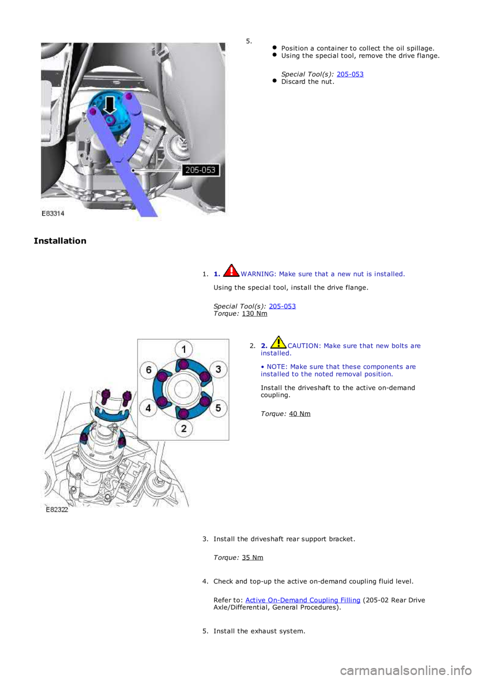
Pos it ion a contai ner t o coll ect t he oil s pill age. Us ing t he s peci al t ool, remove the drive flange.
Speci al Tool (s ): 205-053 Di scard the nut .5.
Installation 1. W ARNING: Make sure t hat a new nut is i nst all ed.
Us ing t he s peci al t ool, i ns t all the drive flange.
Speci al Tool (s ): 205-053 T orque:
130 Nm 1.
2. CAUTION: Make s ure t hat new bolt s are
ins tal led.
• NOTE: Make s ure t hat thes e component s are
ins tal led t o t he noted removal pos it ion.
Ins t al l the drives haft to the act ive on-demand
coupli ng.
T orque: 40 Nm 2.
Inst all t he dri ves haft rear s upport bracket .
T orque: 35 Nm 3.
Check and top-up the acti ve on-demand coupl ing fluid level.
Refer t o: Act ive On-Demand Coupl ing Fi lli ng (205-02 Rear Drive
Axle/Different ial, General Procedures).
4.
Inst all t he exhaus t sys t em.
5.
Page 359 of 3229
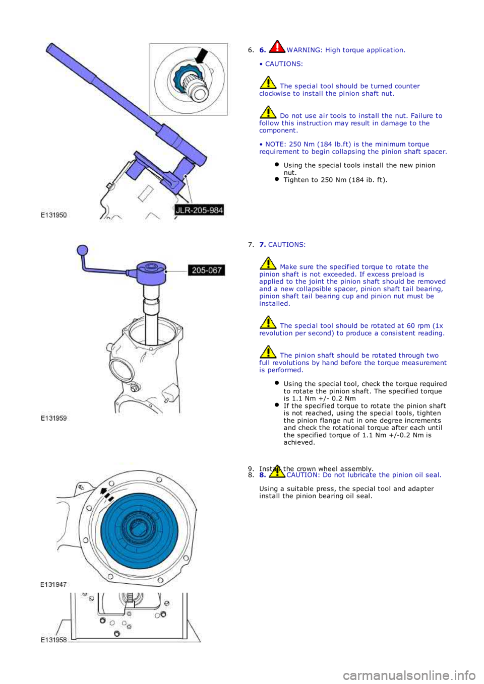
6. W ARNING: High t orque applicat ion.
• CAUTIONS:
The s peci al tool s hould be t urned count erclockwis e t o ins t al l the pi nion s haft nut.
Do not us e ai r tools to i nst all t he nut. Fail ure t ofol low thi s ins truct ion may res ult i n damage t o thecomponent .
• NOTE: 250 Nm (184 lb.ft) i s t he mi ni mum torquerequi rement to begi n collaps ing t he pini on s haft s pacer.
Us ing t he s peci al t ools i nst all t he new pini onnut.Tight en to 250 Nm (184 ib. ft).
6.
7. CAUTIONS:
Make s ure the specified t orque t o rot ate thepini on s haft is not exceeded. If exces s prel oad isapplied to the joint t he pinion s haft s hould be removedand a new col lapsi ble s pacer, pinion shaft tail beari ng,pini on s haft tai l bearing cup and pinion nut mus t bei ns t alled.
The s peci al tool s hould be rot ated at 60 rpm (1xrevolut ion per s econd) t o produce a cons i st ent reading.
The pi ni on s haft s houl d be rotat ed through t woful l revolut ions by hand before the t orque meas urementi s performed.
Us ing t he s peci al t ool, check t he t orque requiredt o rot ate the pi nion s haft . The specified t orquei s 1.1 Nm +/- 0.2 NmIf the s pecifi ed t orque t o rot ate the pi ni on s hafti s not reached, usi ng t he s pecial t ool s, t ight ent he pinion flange nut in one degree increment sand check t he rot ati onal t orque after each unt ilt he s pecified t orque of 1.1 Nm +/-0.2 Nm i sachi eved.
7.
8. CAUTION: Do not l ubricate the pi ni on oil s eal.
Us ing a s ui table pres s, t he s peci al t ool and adapt eri ns t all the pi nion beari ng oil s eal .
8.Inst all t he crown wheel ass embly.9.
Page 362 of 3229
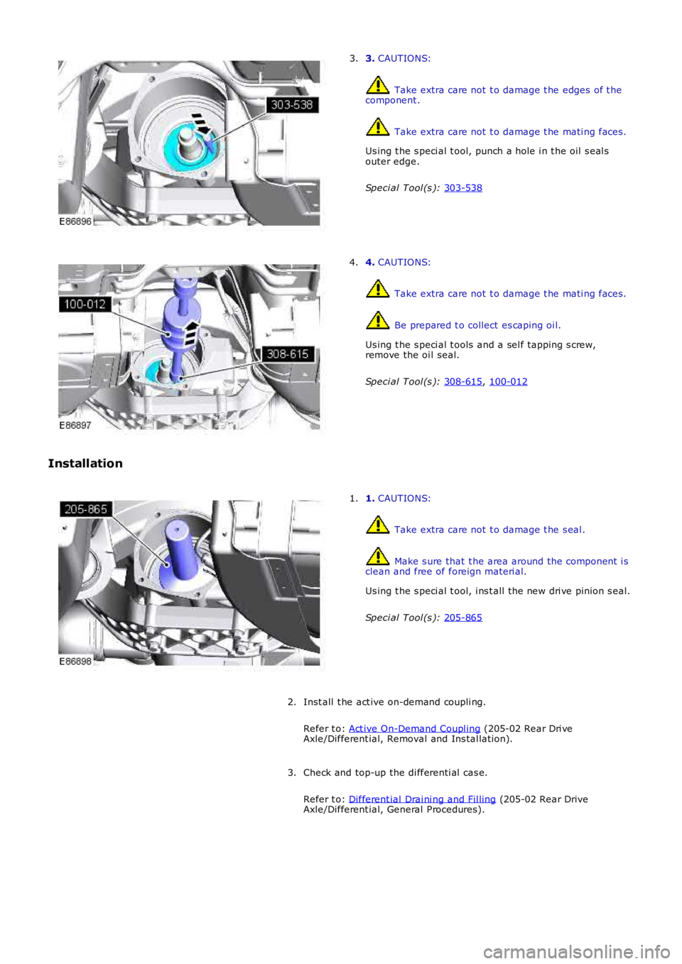
3.
CAUTIONS: Take extra care not t o damage t he edges of t he
component . Take extra care not t o damage t he mati ng faces .
Us ing t he s peci al t ool, punch a hole i n t he oil s eal s
outer edge.
Speci al Tool (s ): 303-538 3.
4.
CAUTIONS: Take extra care not t o damage t he mati ng faces .
Be prepared t o collect es caping oi l.
Us ing t he s peci al t ools and a sel f tapping s crew,
remove the oi l seal.
Speci al Tool (s ): 308-615 ,
100-012 4.
Installation 1.
CAUTIONS: Take extra care not t o damage t he s eal .
Make s ure that t he area around the component i s
clean and free of foreign materi al.
Us ing t he s peci al t ool, i ns t all the new dri ve pinion s eal.
Speci al Tool (s ): 205-865 1.
Inst all t he act ive on-demand coupli ng.
Refer t o: Act ive On-Demand Coupl ing (205-02 Rear Dri ve
Axle/Different ial, Removal and Ins tal lati on).
2.
Check and top-up the di fferenti al cas e.
Refer t o: Different ial Drai ni ng and Fil ling (205-02 Rear Drive
Axle/Different ial, General Procedures).
3.
Page 375 of 3229
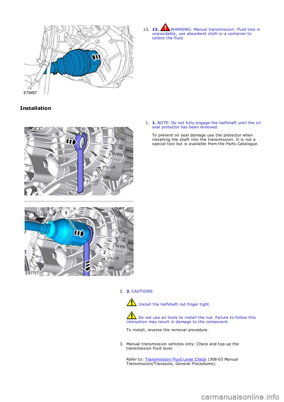
13. W ARNING: Manual transmis s ion: Fl uid l oss isunavoi dabl e, us e abs orbent cl oth or a cont ai ner t ocollect t he fl uid.
13.
Installation
1. NOTE: Do not ful ly engage the hal fs haft unti l the oi ls eal protector has been removed.
To prevent oil s eal damage us e t he prot ect or wheni ns t alli ng t he shaft int o the trans mi s si on. It is not as peci al t ool but i s avai lable from t he Part s Catal ogue.
1.
2. CAUTIONS:
Ins tall t he halfshaft nut finger ti ght .
Do not us e ai r tools to i nst all t he nut. Fail ure t o follow thi si ns t ructi on may resul t in damage t o t he component.
To i nst all , revers e t he removal procedure.
2.
Manual t rans mi ss i on vehi cl es onl y: Check and t op-up t het rans mis s ion flui d level.
Refer t o: Transmis s ion Flui d Level Check (308-03 ManualTrans mi ss ion/Transaxle, General Procedures).
3.
Page 603 of 3229
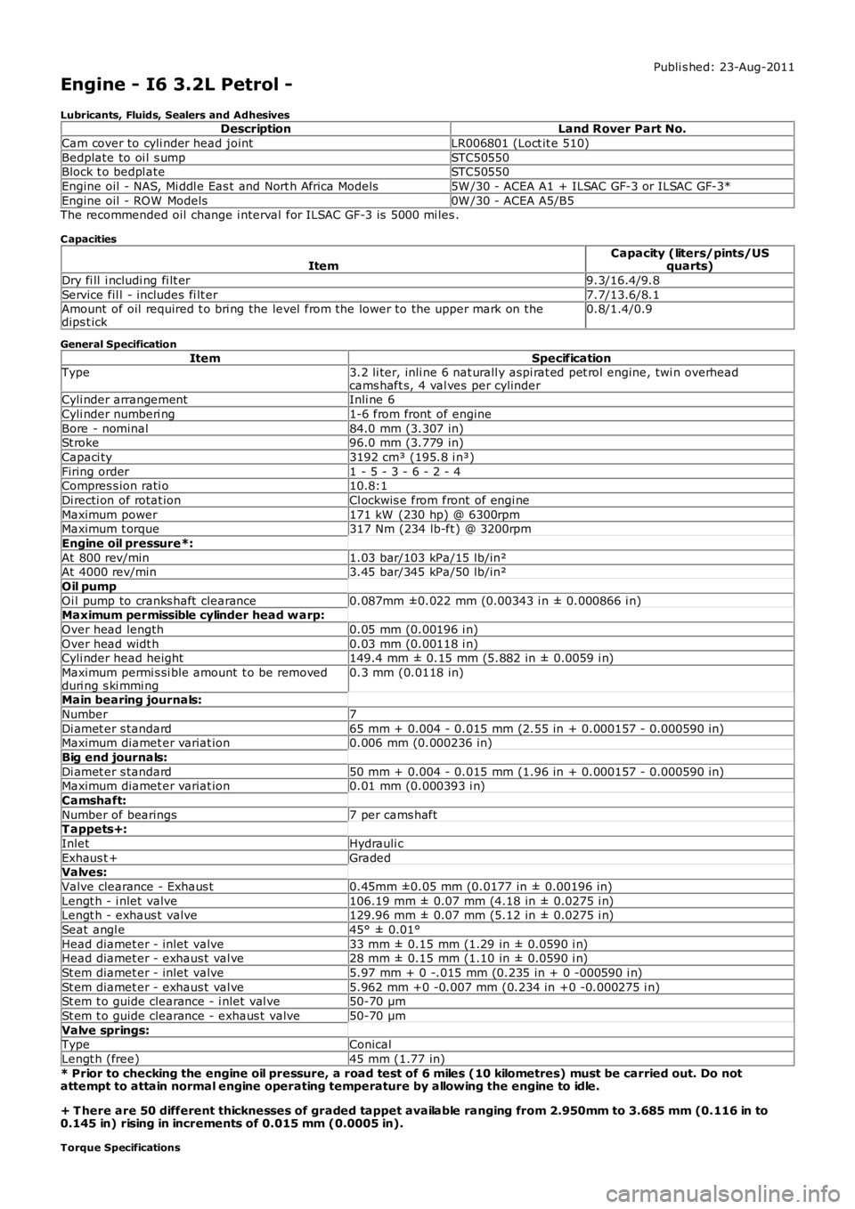
Publi s hed: 23-Aug-2011
Engine - I6 3.2L Petrol -
Lubricants, Fluids, Sealers and AdhesivesDescriptionLand Rover Part No.
Cam cover to cyli nder head jointLR006801 (Loct it e 510)
Bedplate to oi l s umpSTC50550Block t o bedpl ateSTC50550
Engine oil - NAS, Mi ddl e Eas t and Nort h Africa Models5W /30 - ACEA A1 + ILSAC GF-3 or ILSAC GF-3*
Engine oil - ROW Models0W /30 - ACEA A5/B5The recommended oil change i nterval for ILSAC GF-3 is 5000 mi les .
C apacities
ItemCapacity (liters/pints/USquarts)
Dry fi ll i ncludi ng fi lt er9.3/16.4/9.8
Service fil l - includes fi lt er7.7/13.6/8.1Amount of oil required t o bri ng the level from the lower to the upper mark on thedips t ick0.8/1.4/0.9
General Specification
ItemSpecificationType3.2 li ter, inli ne 6 nat urall y aspi rat ed pet rol engine, twi n overheadcams haft s, 4 val ves per cylinderCyli nder arrangementInli ne 6
Cyli nder numberi ng1-6 from front of engine
Bore - nominal84.0 mm (3.307 in)St roke96.0 mm (3.779 in)
Capaci ty3192 cm³ (195.8 i n³)
Firing order1 - 5 - 3 - 6 - 2 - 4Compres s ion rati o10.8:1
Di recti on of rotat ionCl ockwis e from front of engi ne
Maximum power171 kW (230 hp) @ 6300rpmMaximum t orque317 Nm (234 lb-ft ) @ 3200rpm
Engine oil pressure*:
At 800 rev/min1.03 bar/103 kPa/15 lb/in²At 4000 rev/min3.45 bar/345 kPa/50 lb/in²
Oil pump
Oi l pump to cranks haft clearance0.087mm ±0.022 mm (0.00343 i n ± 0.000866 i n)Maximum permissible cylinder head w arp:
Over head length0.05 mm (0.00196 i n)
Over head widt h0.03 mm (0.00118 i n)Cyli nder head height149.4 mm ± 0.15 mm (5.882 in ± 0.0059 i n)
Maximum permi s si ble amount t o be removedduri ng s ki mmi ng0.3 mm (0.0118 in)
Main bearing journals:
Number7
Di amet er s tandard65 mm + 0.004 - 0.015 mm (2.55 in + 0.000157 - 0.000590 in)Maximum diamet er variat ion0.006 mm (0.000236 in)
Big end journals:
Di amet er s tandard50 mm + 0.004 - 0.015 mm (1.96 in + 0.000157 - 0.000590 in)Maximum diamet er variat ion0.01 mm (0.000393 i n)
Camshaft:
Number of bearings7 per cams haftT appets+:
InletHydrauli c
Exhaus t +GradedValves:
Valve clearance - Exhaus t0.45mm ±0.05 mm (0.0177 in ± 0.00196 in)
Lengt h - i nlet valve106.19 mm ± 0.07 mm (4.18 in ± 0.0275 i n)Lengt h - exhaus t valve129.96 mm ± 0.07 mm (5.12 in ± 0.0275 i n)
Seat angl e45° ± 0.01°
Head diamet er - inlet valve33 mm ± 0.15 mm (1.29 in ± 0.0590 i n)Head diamet er - exhaus t val ve28 mm ± 0.15 mm (1.10 in ± 0.0590 i n)
St em diamet er - inlet valve5.97 mm + 0 -.015 mm (0.235 in + 0 -000590 i n)
St em diamet er - exhaus t val ve5.962 mm +0 -0.007 mm (0.234 in +0 -0.000275 i n)St em t o guide clearance - i nlet val ve50-70 µm
St em t o guide clearance - exhaus t valve50-70 µm
Valve springs:TypeConical
Lengt h (free)45 mm (1.77 in)
* Prior to checking the engine oil pressure, a road test of 6 miles (10 kilometres) must be carried out. Do notattempt to attain normal engine operating temperature by allowing the engine to idle.
+ T here are 50 different thicknesses of graded tappet available ranging from 2.950mm to 3.685 mm (0.116 in to0.145 in) rising in increments of 0.015 mm (0.0005 in).
Torque Specifications
Page 647 of 3229
SymptomAction
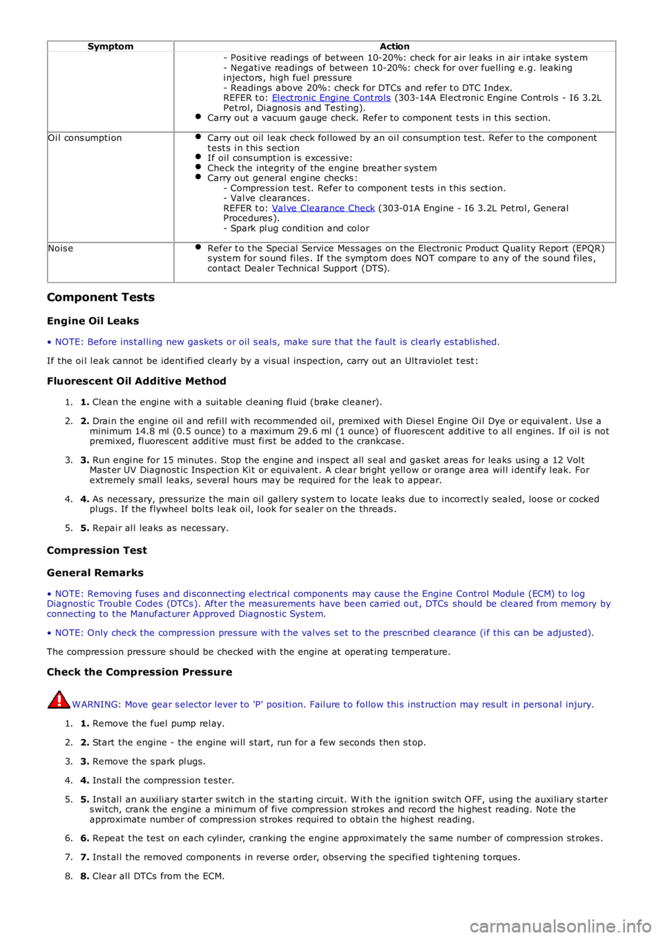
- Pos it ive readi ngs of bet ween 10-20%: check for air leaks i n air i nt ake s ys t em- Negati ve readings of between 10-20%: check for over fuell ing e.g. leaki ngi njectors , high fuel pres sure- Readings above 20%: check for DTCs and refer t o DTC Index.REFER t o: El ect ronic Engi ne Cont rol s (303-14A El ect roni c Engi ne Cont rol s - I6 3.2LPet rol, Di agnos is and Tes ti ng).Carry out a vacuum gauge check. Refer to component t es ts i n t his s ecti on.
Oi l cons umpti onCarry out oil l eak check fol lowed by an oi l cons umpt ion tes t. Refer t o t he componentt est s i n t hi s s ect ionIf oil cons umpt ion i s exces si ve:Check the integrit y of the engine breat her sys t emCarry out general engi ne checks :- Compress ion tes t. Refer t o component t es ts i n t his s ect ion.- Val ve cl earances .REFER t o: Val ve Clearance Check (303-01A Engine - I6 3.2L Pet rol , GeneralProcedures ).- Spark pl ug condi ti on and col or
Nois eRefer t o t he Speci al Servi ce Mess ages on t he Electroni c Product Q ual it y Report (EPQR)s ys tem for s ound fi les . If t he s ympt om does NOT compare t o any of the s ound files ,contact Deal er Technical Support (DTS).
Component Tests
Engine Oil Leaks
• NOTE: Before ins t al li ng new gasket s or oil s eal s, make sure t hat t he faul t is cl early es t abl is hed.
If the oi l l eak cannot be ident ifi ed clearl y by a vi sual ins pect ion, carry out an Ult raviolet t est :
Fluorescent Oil Additive Method
1. Clean t he engi ne wit h a sui table cl eani ng fl uid (brake cleaner).1.
2. Drai n the engi ne oil and refil l wit h recommended oil , premixed wi th Dies el Engine Oil Dye or equi val ent . Us e aminimum 14.8 ml (0.5 ounce) t o a maxi mum 29.6 ml (1 ounce) of fl uores cent addit ive to all engines. If oil i s notpremixed, fl uorescent addi ti ve mus t fi rs t be added to the crankcas e.
2.
3. Run engi ne for 15 minutes . Stop the engine and i nspect all s eal and gas ket areas for leaks us ing a 12 Vol tMas t er UV Diagnost ic Ins pect ion Ki t or equivalent . A clear bri ght yell ow or orange area wil l i dent ify l eak. Forext remely smal l leaks, s everal hours may be required for t he leak t o appear.
3.
4. As neces s ary, pres surize t he main oil gallery s yst em t o l ocat e leaks due t o incorrect ly sealed, loos e or cockedpl ugs . If the flywheel bol ts l eak oil, l ook for s ealer on t he threads .4.
5. Repai r al l leaks as neces s ary.5.
Compression Test
General Remarks
• NOTE: Removing fuses and di sconnect ing elect rical components may caus e t he Engine Control Modul e (ECM) t o l ogDiagnost ic Troubl e Codes (DTCs ). Aft er t he meas urements have been carried out , DTCs should be cl eared from memory byconnecti ng to the Manufact urer Approved Diagnos t ic Sys tem.
• NOTE: Only check the compress ion pres sure wit h t he valves s et to the pres cri bed clearance (i f thi s can be adjus ted).
The compres si on pres s ure s hould be checked wi th the engine at operat ing temperat ure.
Check the Comp ression Pressure
W ARNING: Move gear s elector lever to 'P' pos i ti on. Fail ure t o follow thi s ins t ructi on may res ult i n pers onal injury.
1. Remove the fuel pump rel ay.1.
2. Start the engine - the engine wi ll s t art, run for a few seconds then s t op.2.
3. Remove the s park pl ugs.3.
4. Ins t al l the compres s ion t es ter.4.
5. Ins t al l an auxi li ary s tarter s wit ch in the st art ing circui t. W it h t he ignit ion swi tch O FF, us ing t he auxi li ary s t arters wi tch, crank the engine a mi ni mum of five compres s ion st rokes and record the hi ghest reading. Not e theapproximat e number of compress i on s trokes requi red t o obt ai n t he highest readi ng.
5.
6. Repeat t he tes t on each cyl inder, cranking t he engine approximat ely t he s ame number of compress i on st rokes .6.
7. Ins t al l the removed components in reverse order, obs erving t he s peci fi ed ti ght ening t orques.7.
8. Clear all DTCs from the ECM.8.
Page 648 of 3229
Interpretation of the Results
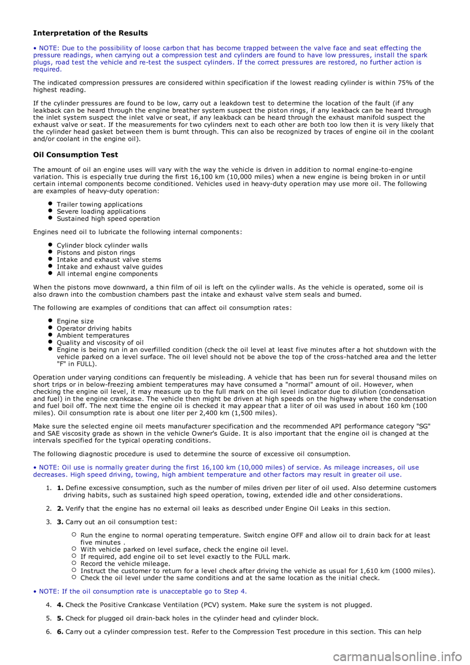
• NOTE: Due t o t he poss ibi li ty of l oos e carbon t hat has become t rapped between t he valve face and seat effect ing thepres s ure readi ngs , when carryi ng out a compres s ion t est and cyli nders are found to have low press ures , ins t al l the s parkplugs , road t est t he vehicle and re-t est the s us pect cyl inders . If the correct pressures are rest ored, no further acti on isrequired.
The indicat ed compress i on pres sures are cons idered wi thi n s pecificati on if t he l owest readi ng cyl inder is wi thi n 75% of t hehighest reading.
If the cyli nder pres s ures are found t o be l ow, carry out a l eakdown t est to det ermi ne the locat ion of t he faul t (i f anyleakback can be heard through t he engine breat her sys tem s uspect the pi st on rings , if any leakback can be heard throught he inlet s ys tem sus pect t he i nl et val ve or seat , if any leakback can be heard through the exhaus t mani fold sus pect t heexhaus t val ve or s eat . If t he meas urements for t wo cyl inders next t o each ot her are bot h t oo low then i t is very likely thatt he cyl inder head gas ket bet ween them is burnt t hrough. Thi s can als o be recognized by t races of engi ne oil in the coolantand/or cool ant i n t he engi ne oil ).
Oil Consump tion Test
The amount of oi l an engi ne uses will vary wit h t he way t he vehi cl e is driven i n addit ion t o normal engine-t o-enginevariat ion. This i s es pecial ly t rue during t he fi rs t 16,100 km (10,000 mil es) when a new engine i s bei ng broken i n or unt ilcert ai n i nt ernal components become condit ioned. Vehicles us ed i n heavy-dut y operati on may us e more oil . The fol lowingare exampl es of heavy-duty operat ion:
Trai ler towi ng appl icati onsSevere loading appli cat ionsSust ained high speed operat ion
Engi nes need oi l to lubri cat e t he fol lowing internal component s :
Cylinder block cyl inder wallsPis t ons and pi st on ringsInt ake and exhaus t val ve s temsInt ake and exhaus t val ve guidesAll i nt ernal engi ne component s
W hen t he pis t ons move downward, a t hi n film of oil i s left on the cyli nder wal ls . As t he vehi cl e is operated, s ome oil i sals o drawn int o t he combus t ion chambers pas t the i ntake and exhaus t valve s tem s eal s and burned.
The fol lowing are examples of condi ti ons that can affect oil consumpt ion rates :
Engi ne s izeOperat or driving habit sAmbient t emperaturesQuali ty and vi scos it y of oi lEngi ne is bei ng run in an overfil led condit ion (check t he oil level at least five minutes after a hot s hutdown wi th thevehi cl e parked on a level surface. The oi l level s hould not be above the top of t he cros s-hatched area and t he l et t er"F" i n FULL).
Operat ion under varyi ng condi ti ons can frequent ly be mi sl eadi ng. A vehi cl e t hat has been run for s everal t housand miles ons hort t rips or i n below-freezi ng ambient temperat ures may have cons umed a "normal" amount of oil . However, whenchecking t he engine oil l evel , it may meas ure up to the full mark on t he oil l evel indicator due t o dil uti on (condens ati onand fuel ) in t he engine crankcas e. The vehi cl e t hen might be driven at high s peeds on the hi ghway where t he condens at ionand fuel boil off. The next t ime t he engi ne oil is checked it may appear that a l it er of oi l was us ed i n about 160 km (100mi les ). Oi l cons umpti on rat e is about one l it er per 2,400 km (1,500 mil es).
Make s ure t he s elected engine oi l meets manufact urer s pecificati on and t he recommended API performance cat egory "SG"and SAE vis cos i ty grade as s hown in t he vehicle O wner's Gui de. It is al s o important t hat t he engine oi l i s changed at t heint ervals s peci fi ed for t he t ypi cal operati ng condi ti ons .
The fol lowing di agnos t ic procedure i s us ed to det ermi ne t he s ource of excess i ve oi l cons umpti on.
• NOTE: Oi l us e i s normal ly great er during the first 16,100 km (10,000 mi les ) of servi ce. As mil eage i ncreas es , oil us edecreas es . High s peed dri vi ng, towing, high ambi ent temperat ure and ot her factors may res ult in great er oil use.
1. Defi ne exces si ve cons umpti on, s uch as t he number of miles driven per li ter of oil used. Al so det ermine cust omersdriving habit s , such as s us tai ned hi gh s peed operat ion, t owing, ext ended i dle and other cons iderat ions.1.
2. Verify t hat the engine has no ext ernal oi l leaks as descri bed under Engine Oi l Leaks i n thi s s ect ion.2.
3. Carry out an oil cons umpti on t es t :
Run t he engi ne to normal operati ng t emperature. Swi tch engine OFF and al low oi l to drain back for at l eas tfi ve mi nut es .W i th vehi cl e parked on l evel s urface, check t he engi ne oil l evel.If required, add engine oil t o s et level exactl y t o t he FULL mark.Record t he vehi cl e mi leage.Ins t ruct the cus tomer t o return for a l evel check after driving t he vehi cle as us ual for 1,610 km (1000 mi les ).Check t he oil l evel under t he s ame condit ions and at the same locat ion as the i nit ial check.
3.
• NOTE: If the oi l cons umpti on rat e is unaccept abl e go t o St ep 4.
4. Check t he Posi ti ve Crankcas e Vent ilat ion (PCV) sys t em. Make sure t he s ys t em i s not pl ugged.4.
5. Check for pl ugged oi l drain-back holes i n t he cyl inder head and cyli nder bl ock.5.
6. Carry out a cyl inder compress ion tes t. Refer t o t he Compres s ion Tes t procedure in thi s s ect ion. Thi s can help6.