2006 LAND ROVER FRELANDER 2 roof
[x] Cancel search: roofPage 1911 of 3229
Publi s hed: 11-May-2011
Antenna - Antenna
Des cript ion and Operat ion
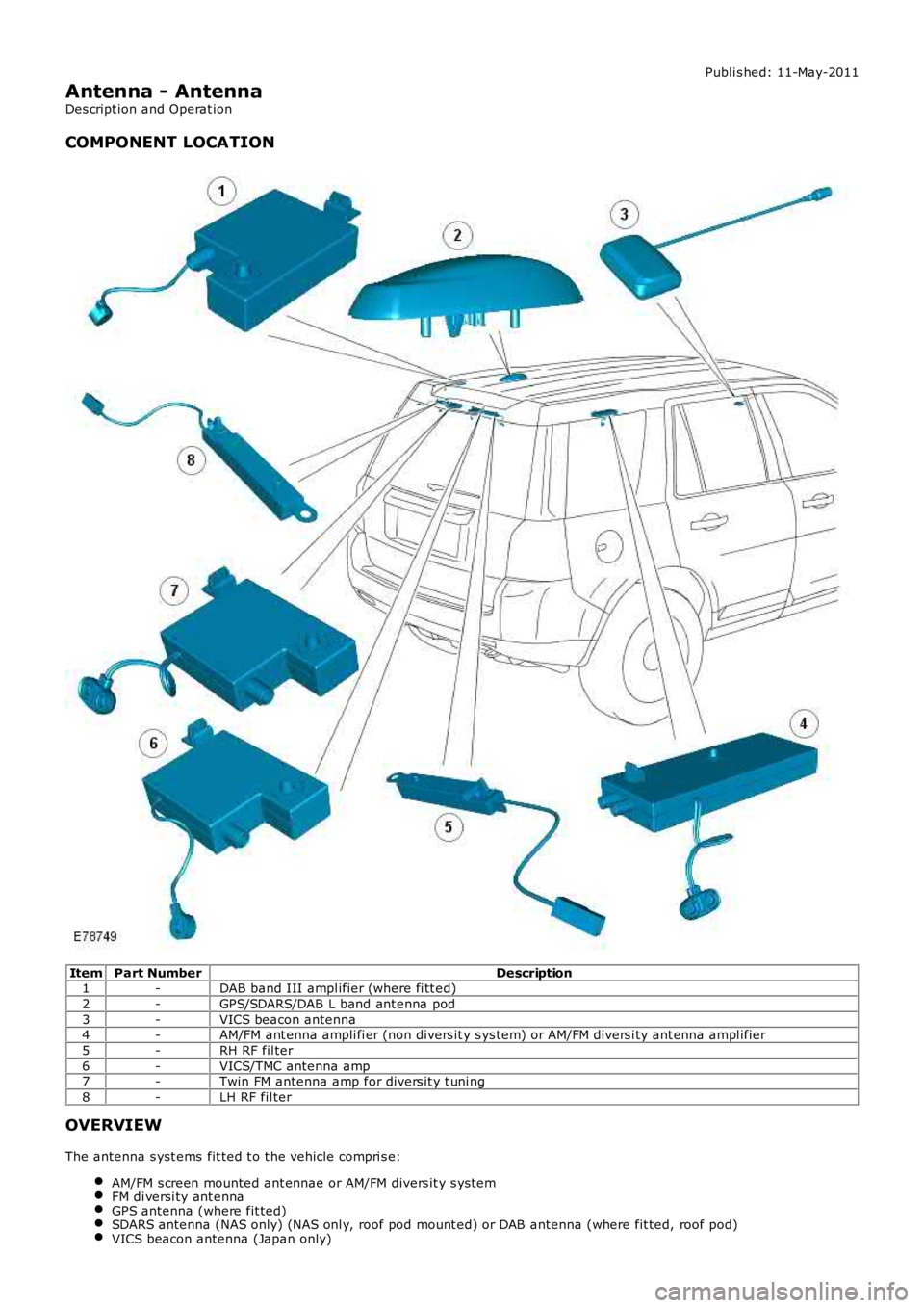
COMPONENT LOCATION
ItemPart NumberDescription1-DAB band III ampl ifier (where fi tt ed)
2-GPS/SDARS/DAB L band ant enna pod
3-VICS beacon antenna4-AM/FM ant enna ampli fi er (non divers it y s ys tem) or AM/FM divers i ty ant enna ampl ifier
5-RH RF fil ter
6-VICS/TMC antenna amp7-Twin FM antenna amp for divers it y t uni ng
8-LH RF fil ter
OVERVIEW
The antenna s yst ems fit ted t o t he vehicle compri s e:
AM/FM s creen mounted ant ennae or AM/FM divers it y s ys temFM di versi ty ant ennaGPS antenna (where fit ted)SDARS antenna (NAS only) (NAS onl y, roof pod mount ed) or DAB antenna (where fit ted, roof pod)VICS beacon antenna (Japan only)
Page 1912 of 3229

Digi tal Audio Broadcast ing (DAB) s yst em ant enna (s ide screen or roof pod mount ed depending on sys t em)
The AM/FM antenna is et ched ont o t he RH s i de window gl as s . The antenna has an ampli fi er locat ed jus t above thewindow. This ampl ifier wil l vary upon the ent ert ainment and informat ion s yst em fi tt ed to the vehicle. Hi gh li ne s ys t emswil l have a larger ampl ifier for divers i ty t uning.
The rear wi ndow incorporat es 2 FM ant ennae and a VICS/TMC ant enna etched onto t he glas s . The 2 FM ant ennae are us edin the di vers it y tuning sys tem along wi th the res pecti ve antenna ampli fi ers .
The LH s ide window antenna i s used for DAB band III s i gnal recepti on.
• NOTE: The t el ephone control modul e incorporat es a Bl uet ooth ant enna. This i s int egral to the modul e and as s uch is nots erviceabl e.
CONTROL DIAGRAM
• NOTE: A = Hardwi red; P = MOST; T = CoAxial
Page 1922 of 3229
The automat ic headlamp s ys tem uses a li ght s ens or and t he CJB, which are connect ed via the LIN bus t o cont rol t heheadl amp funct ional it y.
A l ight s ens or is incorporated in t he rai n/l ight s ens or located on the i nsi de of the windshi el d, bel ow t he rear view mirror.The wiper s yst em al s o uses the rain/l ight s ens or for aut omati c wiper operati on.For addit ional informat ion, refer t o: W i pers and W as hers (501-16 W ipers and W as hers , Des cri pti on and Operati on).
The li ght sens or meas ures the ambi ent l ight around t he vehi cl e i n a vert ical direct ion and als o the angular li ght l evel fromt he front of t he vehi cle. The rai n/li ght sens or us es vehicle s peed s ignals , wiper s wit ch posi ti on and the park posi ti on of thefront wipers to control the s ys tem.
The automat ic headlamp operat ion us es ambient l ight levels whi ch are moni tored by phot odiodes incorporat ed in t herai n/l ight sens or. The rain/l ight s ens or s ends a li ght s on/off request t o t he CJB on t he LIN bus , which res ponds bys wit chi ng on t he low beam headl amps, front s ide l amps, l icense plate lamps and rear t ail l amps. The aut omat ic headlampsare act ivated under the foll owing condi ti ons :
Twil ightDarknessRainTunnel sUnderground or mult is t ori ed car parks .
Operat ion of t he aut omat ic headl amps requires t he ignit ion t o be on (power mode 6), the l ighti ng cont rol rot ary swi tch t obe i n the 'AUTO' pos it ion and a li ght s on reques t s ignal from t he li ght sens or.
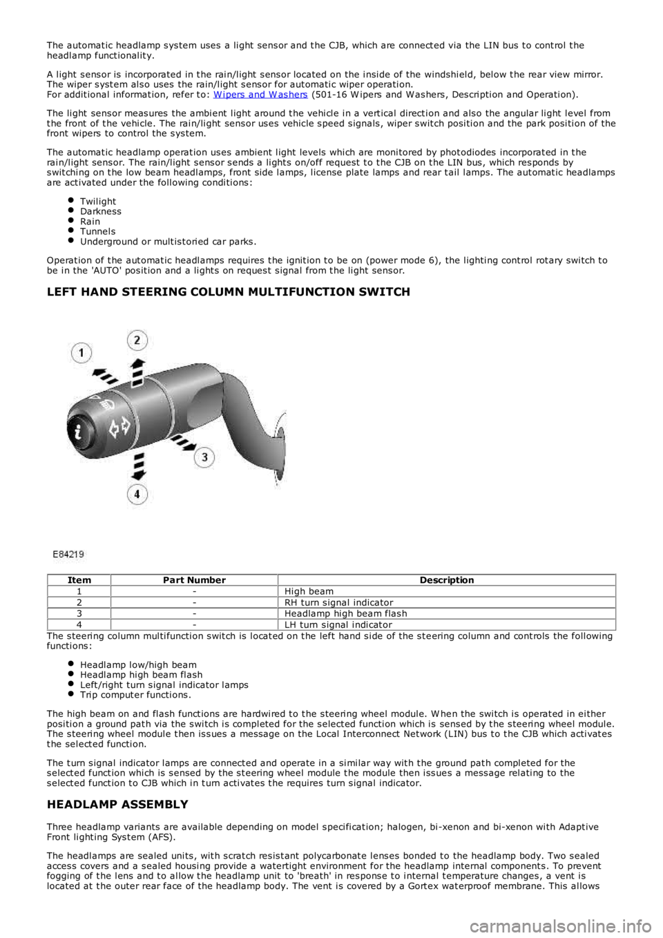
LEFT HAND STEERING COLUMN MULTIFUNCTION SWITCH
ItemPart NumberDescription
1-Hi gh beam
2-RH turn s ignal indicator3-Headlamp hi gh beam flas h
4-LH turn s ignal i ndi cat or
The s teeri ng column mul ti functi on s wit ch is l ocat ed on t he left hand s i de of the s t eering column and cont rols the foll owingfuncti ons :
Headl amp l ow/high beamHeadl amp hi gh beam fl ashLeft /right turn s ignal indicator l ampsTri p comput er functi ons .
The high beam on and fl ash funct ions are hardwi red t o t he s teeri ng wheel modul e. W hen the swi tch i s operat ed in ei therposi ti on a ground pat h via the s wi tch i s compl eted for the s elect ed functi on which is sens ed by t he s teeri ng wheel modul e.The s teeri ng wheel modul e t hen is s ues a mes sage on the Local Interconnect Net work (LIN) bus t o t he CJB which acti vat est he sel ect ed functi on.
The t urn s ignal indicator l amps are connect ed and operate in a si mi lar way wit h t he ground pat h compl eted for thes elect ed funct ion whi ch is s ensed by the s t eering wheel module t he module then i ss ues a mess age rel ati ng to thes elect ed funct ion t o CJB which i n t urn acti vat es t he requires turn s ignal indicator.
HEADLAMP ASSEMBLY
Three headlamp variants are available depending on model s peci fi cat ion; halogen, bi -xenon and bi-xenon wi th Adapt iveFront li ght ing Sys t em (AFS).
The headl amps are sealed uni ts , wit h s crat ch res is t ant polycarbonat e l ens es bonded to the headlamp body. Two s ealedacces s covers and a s ealed housi ng provide a waterti ght environment for the headlamp internal component s . To preventfogging of t he l ens and t o al low t he headlamp unit to 'breath' in res pons e t o i nternal t emperature changes , a vent i slocated at t he outer rear face of the headlamp body. The vent i s covered by a Gort ex wat erproof membrane. This al lows
Page 1953 of 3229
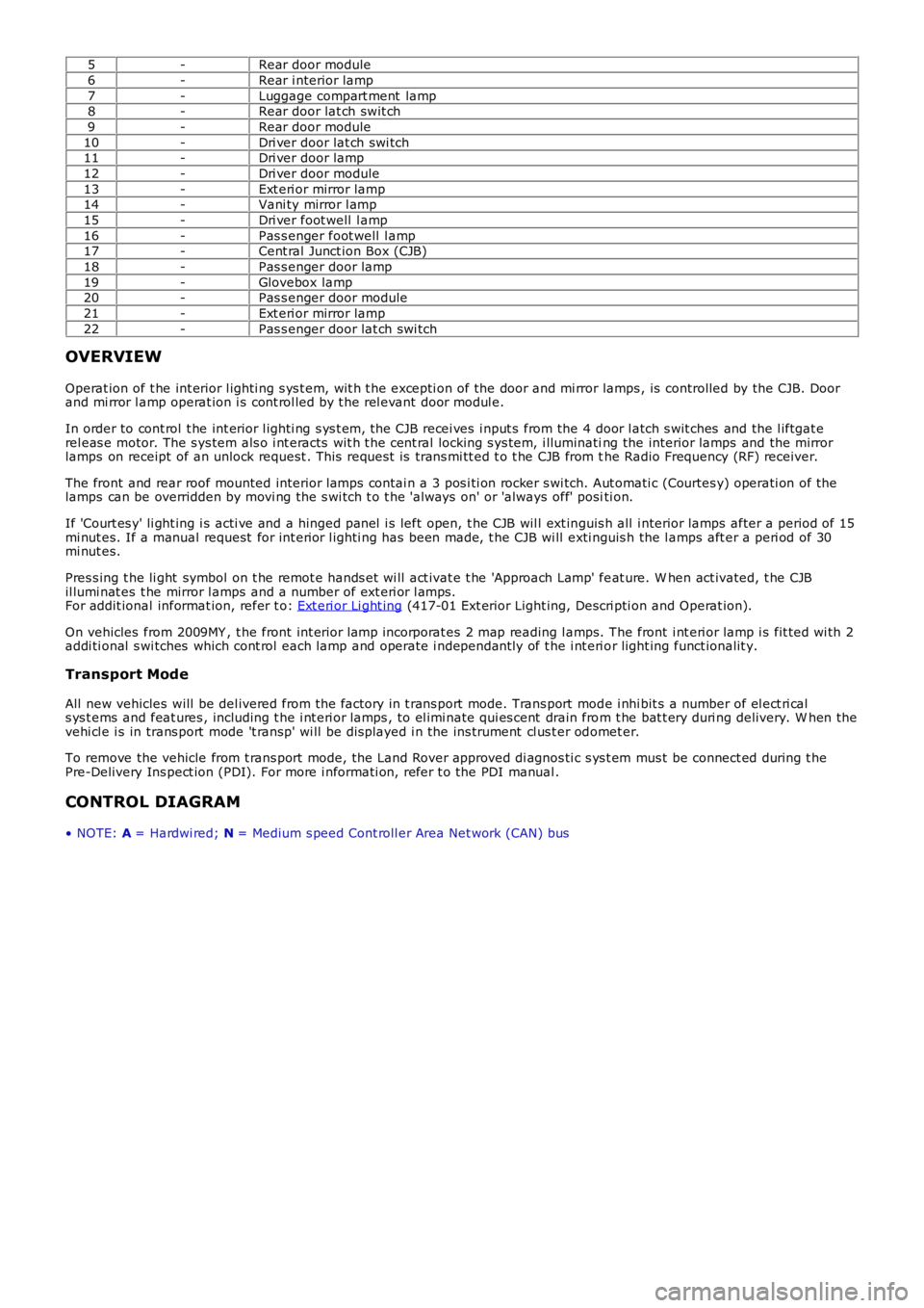
5-Rear door module
6-Rear i nterior lamp
7-Luggage compart ment lamp8-Rear door lat ch swit ch
9-Rear door module
10-Dri ver door lat ch swi tch11-Dri ver door lamp
12-Dri ver door module
13-Ext eri or mirror lamp14-Vani ty mirror l amp
15-Dri ver foot well l amp
16-Pas s enger foot well l amp17-Cent ral Junct ion Box (CJB)
18-Pas s enger door lamp
19-Glovebox lamp20-Pas s enger door module
21-Ext eri or mirror lamp
22-Pas s enger door lat ch swi tch
OVERVIEW
Operat ion of t he int erior l ighti ng s ys t em, wit h t he excepti on of the door and mi rror lamps , is controlled by the CJB. Doorand mi rror l amp operat ion i s cont rol led by t he rel evant door modul e.
In order to cont rol t he int erior l ighti ng s ys t em, the CJB recei ves i nput s from the 4 door l atch s wit ches and the l iftgat erel eas e motor. The s ys tem als o i nt eracts wit h t he cent ral locking s ys tem, i lluminating the interior lamps and the mirrorlamps on receipt of an unlock request . This reques t is trans mi tt ed t o t he CJB from the Radio Frequency (RF) receiver.
The front and rear roof mounted interior lamps contai n a 3 pos i ti on rocker s wi tch. Aut omati c (Courtes y) operati on of thelamps can be overridden by movi ng the s wi tch t o t he 'al ways on' or 'always off' positi on.
If 'Court es y' li ght ing i s acti ve and a hinged panel i s left open, t he CJB wil l ext inguis h all i nterior lamps after a period of 15mi nut es. If a manual request for int erior l ighti ng has been made, t he CJB wi ll exti nguis h the l amps aft er a peri od of 30mi nut es.
Pres s ing t he li ght symbol on t he remot e hands et wi ll act ivat e t he 'Approach Lamp' feat ure. W hen act ivated, t he CJBil lumi nat es t he mirror l amps and a number of ext eri or l amps.For addit ional informat ion, refer t o: Ext eri or Li ght ing (417-01 Ext erior Light ing, Descri pti on and Operat ion).
On vehicles from 2009MY , t he front int erior l amp incorporat es 2 map reading l amps. The front i nt eri or lamp i s fit ted wi th 2addi ti onal s wi tches which cont rol each lamp and operate i ndependant ly of t he i nt eri or light ing funct ionalit y.
Transport Mode
All new vehicles will be del ivered from the factory in t rans port mode. Trans port mode i nhi bit s a number of el ect ri cals ys t ems and feat ures , including t he i nt eri or lamps , to el imi nate qui es cent drain from t he bat t ery duri ng delivery. W hen thevehi cl e i s in trans port mode 't ransp' wi ll be dis played i n the ins trument cl us t er odomet er.
To remove the vehicle from t rans port mode, the Land Rover approved di agnos ti c s ys t em mus t be connect ed during t hePre-Delivery Ins pect ion (PDI). For more i nformati on, refer t o the PDI manual .
CONTROL DIAGRAM
• NOTE: A = Hardwi red; N = Medium s peed Cont roll er Area Net work (CAN) bus
Page 1956 of 3229
Publi s hed: 11-May-2011
Interior Lighting - Interior Lighting
Diagnosi s and Tes ti ng
Principles of Operation
For a detail ed descripti on of the interior li ght ing sys tem, refer t o t he rel evant Des cript ion and Operat ion s ecti on in theworks hop manual .REFER to: Interior Lighti ng (417-02 Int erior Light ing, Descri pti on and Operat ion).
Inspection and Verification
CAUTION: Di agnos is by s ubs ti tut ion from a donor vehicle is NO T acceptabl e. Subs ti tut ion of cont rol modules doesnot guarant ee confirmat ion of a faul t, and may als o caus e addit ional fault s i n t he vehi cl e being t est ed and/or t he donorvehi cl e.
1. Verify t he cus t omer concern.1.
2. Vis ually ins pect for obvious s igns of mechani cal or electrical damage.2.
Visual InspectionMechanicalElectrical
BulbsFus es/rel ays (refer to electrical gui de)W iring harnes sCorrect engagement of elect rical connect orsLoos e or corroded connecti ons
3. If an obvious cause for an obs erved or report ed concern is found, correct t he caus e (if pos s ible) beforeproceeding t o t he next s t ep.3.
4. If t he caus e is not vis ually evi dent , check for Di agnos ti c Trouble Codes (DTCs) and refer t o t he DTC Index.4.
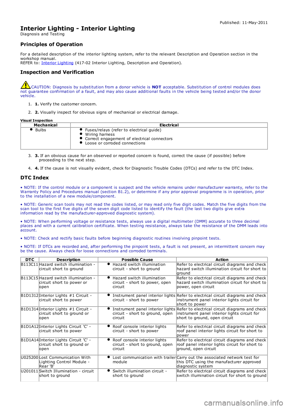
DTC Index
• NOTE: If the control modul e or a component i s s us pect and the vehicle remains under manufacturer warrant y, refer t o theW arranty Pol icy and Procedures manual (s ect ion B1.2), or determine i f any pri or approval programme is in operat ion, pri ort o the ins tall ati on of a new module/component.
• NOTE: Generic scan t ool s may not read the codes li st ed, or may read only fi ve digit codes . Mat ch the five di git s from t hes can tool to the firs t fi ve di git s of the seven digi t code l is ted to ident ify t he faul t (t he las t t wo digi ts gi ve ext rainformat ion read by the manufact urer-approved diagnost ic s ys tem).
• NOTE: W hen performing volt age or res is t ance t est s , always use a digi tal mult imeter (DMM) accurat e t o t hree deci malplaces and wit h a current cal ibrat ion cert ificate. W hen tes ti ng res i st ance, always take the res is tance of the DMM l eads i ntoaccount.
• NOTE: Check and recti fy bas ic faul ts before beginni ng diagnos t ic rout ines i nvol vi ng pinpoint t es t s.
• NOTE: If DTCs are recorded and, aft er performi ng the pi npoi nt tes ts , a fault is not present , an int ermi tt ent concern maybe t he caus e. Always check for loose connect ions and corroded terminals .
DT CDescriptionPossible CauseActionB113C11Hazard swit ch ill uminat ion -ci rcuit s hort t o groundHazard s wi tch i lluminati oncircui t - s hort to groundRefer t o elect rical circuit di agrams and checkhazard s wi tch i llumi nati on ci rcuit for short toground
B113C15Hazard swit ch ill uminat ion -ci rcuit s hort t o power oropen
Hazard s wi tch i lluminati oncircui t - s hort to power, opencircui t
Refer t o elect rical circuit di agrams and checkhazard s wi tch i llumi nati on ci rcuit for short topower, open circui t
B1D1312Interior Lights #1 Circui t -ci rcuit s hort t o powerInst rument panel i nterior li ght scircui t - s hort to powerRefer t o elect rical circuit di agrams and checki ns t rument panel i nterior li ght s circui t fors hort t o power
B1D1314Interior Lights #1 Circui t -ci rcuit s hort t o ground oropen
Inst rument panel i nterior li ght scircui t - s hort to ground, opencircui t
Refer t o elect rical circuit di agrams and checki ns t rument panel i nterior li ght s circui t fors hort t o ground, open ci rcuit
B1D1A12Interior Lights Circuit 'C' -ci rcuit s hort t o powerRoof cons ole i nterior li ght scircui t - s hort to powerRefer t o elect rical circuit di agrams and checkroof panel interior li ghts circui t for s hort t opowerB1D1A14Interior Lights Circuit 'C' -ci rcuit s hort t o ground oropen
Roof cons ole i nterior li ght scircui t - s hort to ground, opencircui t
Refer t o elect rical circuit di agrams and checkroof panel interior li ghts circui t for s hort t oground, open ci rcuit
U025200Los t Communicati on W i thLi ght ing Cont rol Modul e -Rear 'B'
Lost communi cat ion wi th trailermoduleCarry out t he ass ociated net work t es t fort his DTC us i ng the manufact urer approveddiagnos ti c sys t em
U201011Swi tch Ill uminat ion - circui ts hort t o groundSwit ch il lumi nat ion ci rcuit -s hort t o groundRefer t o elect rical circuit di agrams and checks wit ch il lumi nat ion ci rcuit for short to ground
Page 2048 of 3229
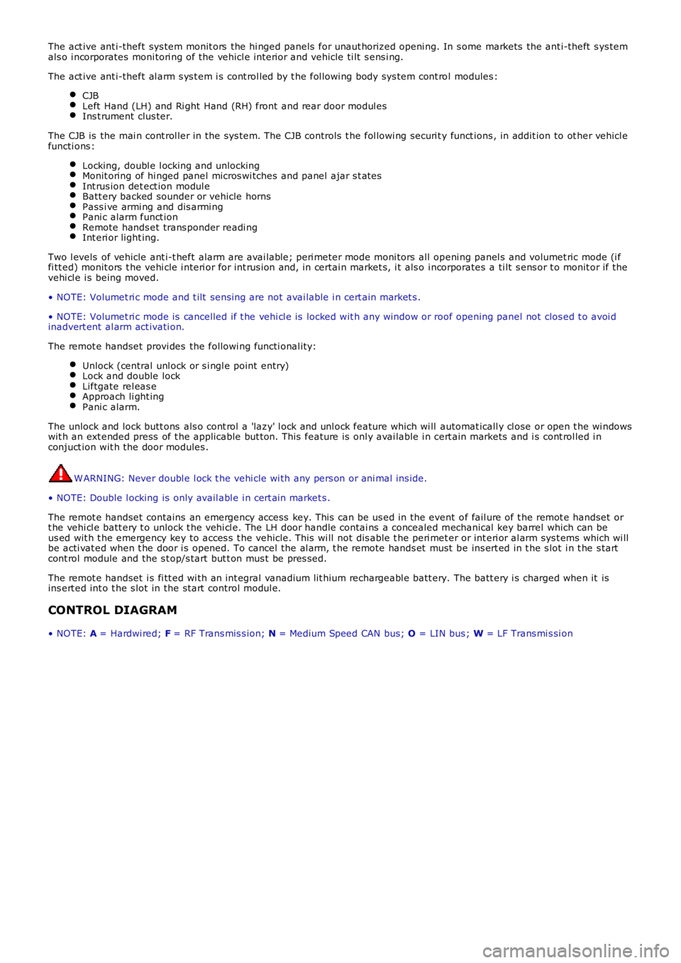
The act ive ant i-theft sys tem monit ors the hi nged panels for unaut horized openi ng. In s ome markets the ant i-theft s ys temals o i ncorporates moni tori ng of the vehicl e int erior and vehicle ti lt s ens i ng.
The act ive ant i-theft al arm s ys t em i s cont rol led by t he fol lowi ng body sys tem cont rol modules :
CJBLeft Hand (LH) and Ri ght Hand (RH) front and rear door modul esIns t rument clus ter.
The CJB is the mai n cont rol ler in the sys tem. The CJB controls t he fol lowi ng securi ty funct ions , in addit ion to ot her vehicl efuncti ons :
Locking, doubl e l ocking and unlockingMonit oring of hi nged panel micros wi tches and panel ajar s t at esInt rus ion det ect ion modul eBatt ery backed sounder or vehicle hornsPass i ve armi ng and dis armi ngPani c alarm funct ionRemote hands et trans ponder readi ngInt eri or light ing.
Two l evels of vehicle ant i-t heft alarm are avai lable; peri meter mode moni tors all openi ng panel s and volumet ric mode (i ffi tt ed) monit ors t he vehi cle i nteri or for int rus ion and, in certai n market s, i t als o i ncorporates a ti lt s ens or t o monit or if t hevehi cl e i s being moved.
• NOTE: Volumet ri c mode and t ilt sens ing are not avai lable i n cert ain market s .
• NOTE: Volumet ri c mode is cancelled if t he vehi cl e is locked wit h any window or roof opening panel not clos ed t o avoi dinadvert ent al arm act ivati on.
The remot e handset provi des the followi ng functi onal it y:
Unlock (central unl ock or s i ngl e point entry)Lock and double lockLiftgate rel eas eApproach li ght ingPani c alarm.
The unlock and lock butt ons als o cont rol a 'lazy' l ock and unl ock feature which wi ll automat icall y cl ose or open t he wi ndowswit h an ext ended press of t he applicable but ton. This feature is onl y avai lable i n cert ain markets and i s cont rol led i nconjuct ion wit h the door modules .
W ARNING: Never doubl e l ock t he vehi cle wi th any pers on or ani mal ins ide.
• NOTE: Double l ocking is only avail abl e i n cert ai n market s .
The remot e handset contains an emergency access key. This can be us ed in the event of fail ure of t he remot e handset ort he vehi cl e batt ery t o unlock t he vehi cl e. The LH door handle contai ns a concealed mechanical key barrel which can beus ed wit h t he emergency key to acces s t he vehicle. This wi ll not dis able t he peri meter or int eri or al arm sys t ems which wi llbe acti vat ed when t he door i s opened. To cancel the al arm, t he remote hands et must be ins ert ed in t he s lot i n t he s tartcont rol module and the s t op/s tart but t on mus t be pres sed.
The remot e handset i s fi tt ed wi th an int egral vanadium lit hium rechargeabl e batt ery. The batt ery i s charged when it isins ert ed int o t he s lot in the st art control modul e.
CONTROL DIAGRAM
• NOTE: A = Hardwi red; F = RF Trans mis s ion; N = Medium Speed CAN bus; O = LIN bus ; W = LF Trans mi s si on
Page 2098 of 3229
Publi s hed: 11-May-2011
Body Closures - Liftgate Alignment
General Procedures
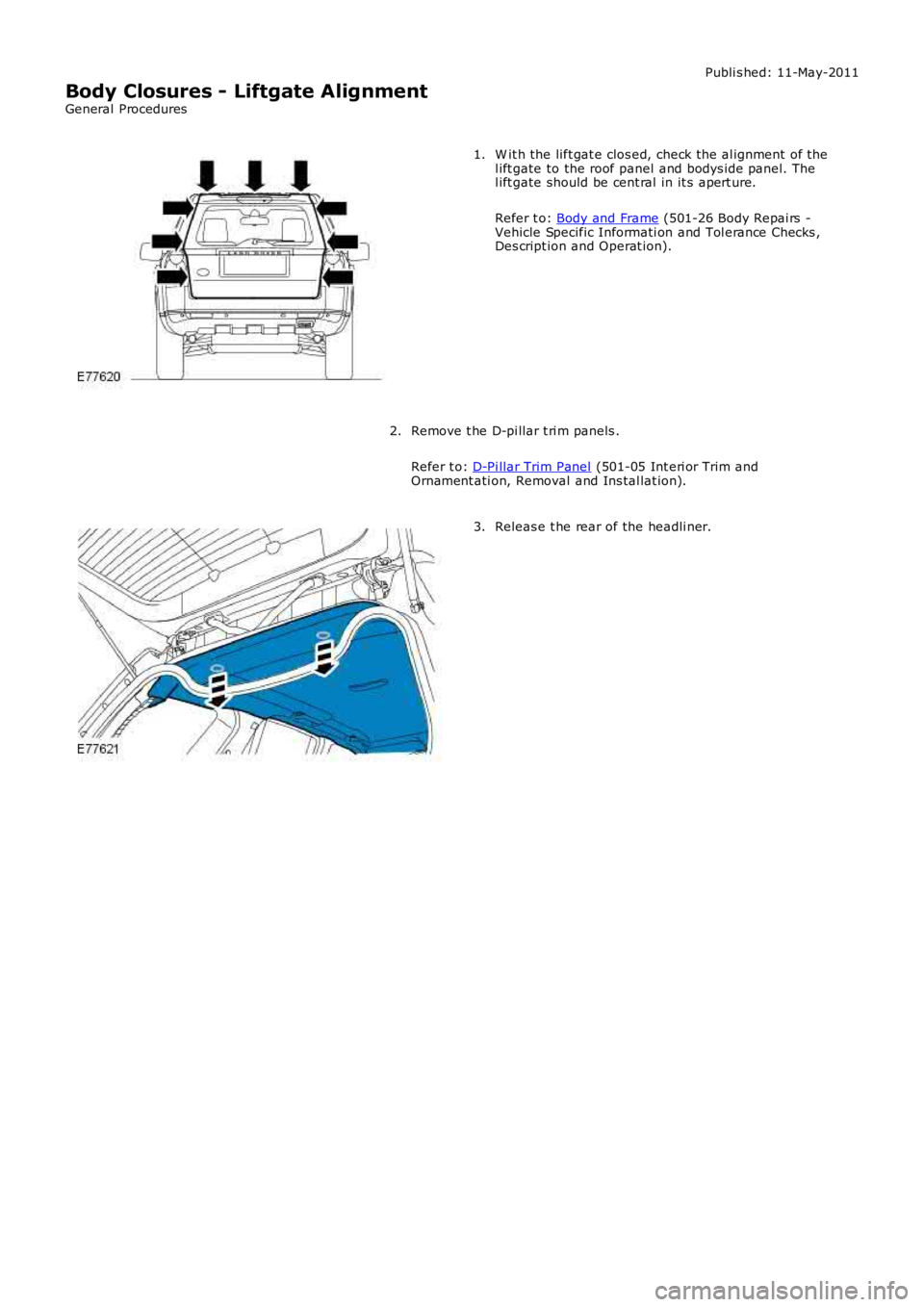
W it h the lift gat e clos ed, check the al ignment of thel ift gate to the roof panel and bodys ide panel. Thel ift gate should be cent ral in it s apert ure.
Refer t o: Body and Frame (501-26 Body Repai rs -Vehicle Specific Informati on and Tol erance Checks ,Des cript ion and Operat ion).
1.
Remove t he D-pi llar t ri m panels .
Refer t o: D-Pi llar Trim Panel (501-05 Int eri or Trim andOrnament ati on, Removal and Ins tal lat ion).
2.
Releas e t he rear of the headli ner.3.
Page 2106 of 3229
At tach t he li ft gat e wi ri ng harness .
3.
Connect t he li ft gat e wi ri ng harnes s electrical connect ors .
4.
W it h the lift gat e clos ed, check the al ignment of the l iftgat e to the
roof panel and bodys ide panel . The li ft gat e s hould be central in i ts
apert ure.
5.
Loosen, but do not remove t he li ft gat e hi nge bol ts .
6.
Pos it ion t he li ft gat e central to t he apert ure.
7.
Tight en the liftgat e hinge bolt s .
T orque: 24 Nm 8.
At tach t he rear of the headli ner.
9.
Inst all t he LH D-pi ll ar upper trim panel .
Refer t o: D-Pi llar Trim Panel (501-05 Int eri or Trim and
Ornament ati on, Removal and Ins tal lat ion).
10.
Check for correct operati on of the lift gat e, and if neces s ary adjus t
t he li ft gat e s t ri ker.
11.