2006 LAND ROVER FRELANDER 2 steering wheel
[x] Cancel search: steering wheelPage 570 of 3229
Publi s hed: 11-May-2011
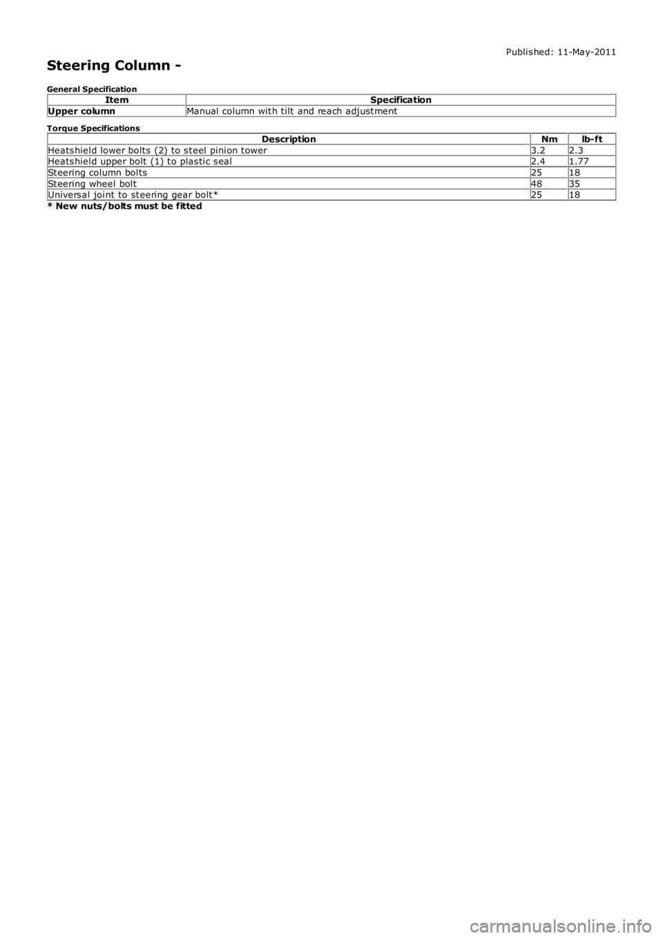
Steering Column -
General SpecificationItemSpecification
Upper columnManual column wit h t ilt and reach adjust ment
Torque Specifications
DescriptionNmlb-ft
Heats hiel d lower bolt s (2) to s t eel pi ni on t ower3.22.3Heats hiel d upper bolt (1) t o plas ti c s eal2.41.77
St eering column bol ts2518
St eering wheel bol t4835Univers al joi nt to st eering gear bolt *2518
* New nuts/bolts must be fitted
Page 571 of 3229
Publi s hed: 11-May-2011
Steering Column - Steering Column
Des cript ion and Operat ion
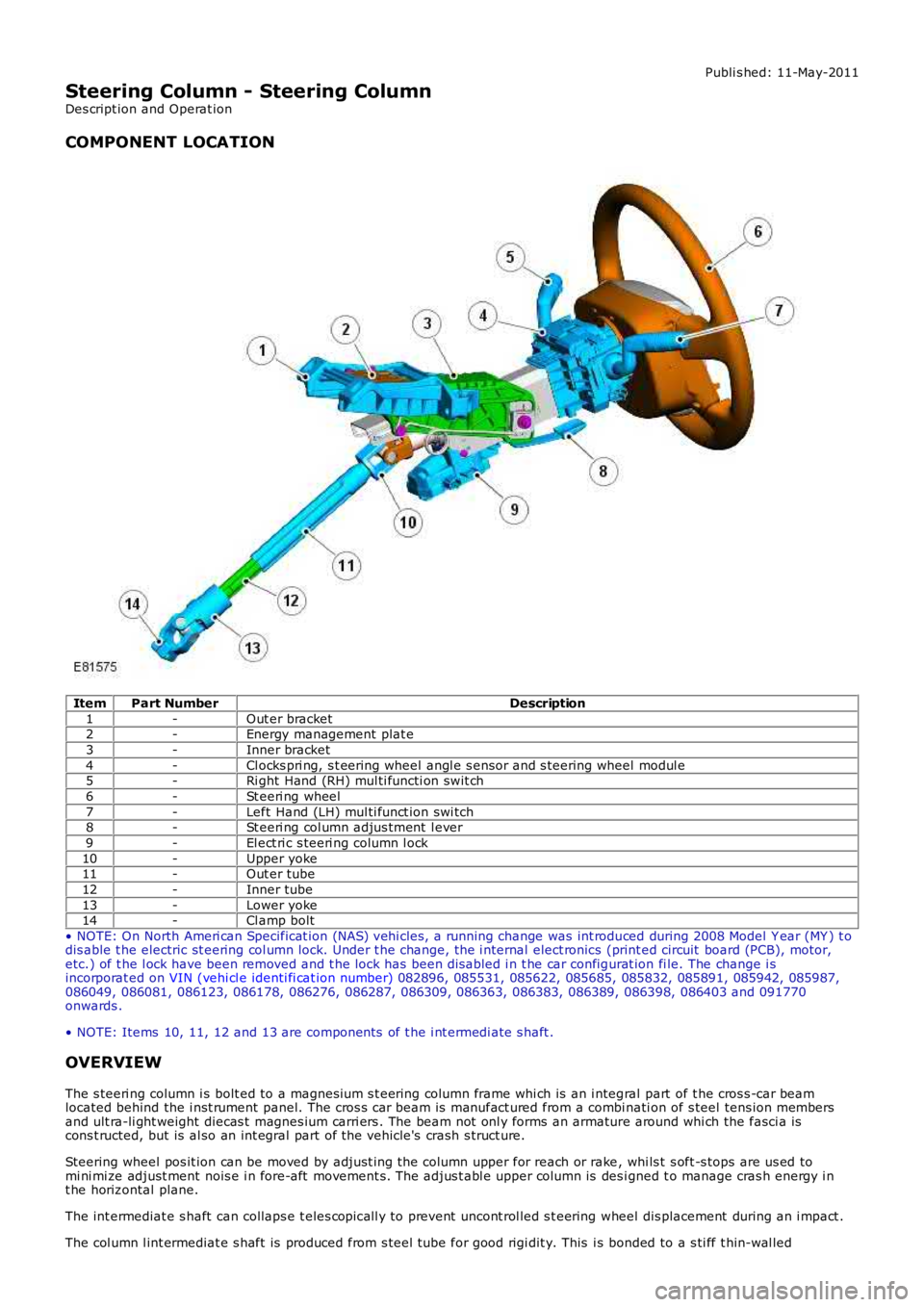
COMPONENT LOCATION
ItemPart NumberDescription
1-Out er bracket2-Energy management plat e
3-Inner bracket
4-Cl ocks pri ng, s t eering wheel angl e s ensor and s teering wheel modul e5-Ri ght Hand (RH) mul ti functi on swit ch
6-St eeri ng wheel
7-Left Hand (LH) mul ti funct ion swi tch8-St eeri ng col umn adjus tment l ever
9-El ect ri c s teeri ng column l ock
10-Upper yoke11-Out er tube
12-Inner tube
13-Lower yoke14-Cl amp bolt
• NOTE: On North Ameri can Specificat ion (NAS) vehi cles , a running change was int roduced during 2008 Model Y ear (MY ) t odis able t he electric st eering col umn lock. Under t he change, the i nternal elect ronics (print ed circuit board (PCB), motor,etc.) of t he l ock have been removed and t he lock has been dis abled i n t he car configurat ion fi le. The change i sincorporat ed on VIN (vehi cl e identi fi cat ion number) 082896, 085531, 085622, 085685, 085832, 085891, 085942, 085987,086049, 086081, 086123, 086178, 086276, 086287, 086309, 086363, 086383, 086389, 086398, 086403 and 091770onwards .
• NOTE: Items 10, 11, 12 and 13 are components of t he i nt ermedi ate s haft .
OVERVIEW
The s teeri ng column i s bolt ed to a magnesi um s t eering column frame whi ch is an i ntegral part of t he cros s -car beamlocated behind the i nst rument panel. The cros s car beam is manufact ured from a combinati on of s teel tens ion membersand ult ra-li ght weight diecas t magnes ium carri ers . The beam not onl y forms an armature around whi ch the fasci a iscons t ructed, but is al so an int egral part of the vehicle's crash s truct ure.
Steering wheel pos it ion can be moved by adjust ing the column upper for reach or rake, whi ls t s oft -s tops are us ed tomi ni mi ze adjust ment nois e i n fore-aft movement s. The adjus t abl e upper column is des igned t o manage cras h energy i nt he horizontal plane.
The int ermediat e s haft can collaps e t eles copicall y to prevent uncont rol led s t eering wheel dis placement during an i mpact .
The col umn l int ermediat e s haft is produced from s teel tube for good rigi dit y. This is bonded to a s ti ff t hin-wal led
Page 572 of 3229
elas tomer t o i sol at e road nois e.
IMPACT PROTECTION
In a s eri ous impact, t he s teeri ng column i s desi gned to manage two si mult aneous event s ; the intermediat e s haft mus tis olat e t he s teeri ng wheel from any movement of t he s t eering rack (i f the angle of the s teering wheel changes it wi ll affectt he way in which t he airbag deploys t owards t he dri ver).
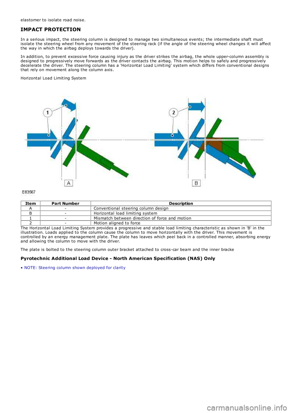
In addi ti on, t o prevent exces s ive force caus ing injury as t he dri ver s trikes t he airbag, t he whole upper-col umn as s embl y i sdesi gned to progres si vel y move forwards as the driver cont act s t he airbag. This mot ion hel ps to safely and progress ivelydecel erate the driver. The s t eering column has a 'Horizont al Load Li mit ing' s ys t em whi ch di ffers from conventi onal des ignst hat rely on movement along t he column axis .
Hori zont al Load Limit ing Sys tem
ItemPart NumberDescriptionA-Convent ional s teeri ng col umn des ign
B-Horizontal load l imi ti ng s yst em
1-Mis match bet ween direct ion of force and moti on2-Mot ion al igned t o force
The Hori zont al Load Limit ing Sys tem provides a progress i ve and st able l oad li mit ing characteris ti c as s hown in 'B' in theil lus trati on. Loads appl ied t o t he column cause the column to move hori zont al ly wit h the driver. Thi s movement i scont rol led by an energy management plat e. The pl ate has l eaves whi ch peel back in a cont roll ed manner, absorbing energyand all owing t he col umn t o move wi th the driver.
The plat e is bol ted t o t he s teering column out er bracket at tached to cross -car beam and t he i nner bracke
Pyrotechnic Additional Load Device - North American Specification (NAS) Only
• NOTE: Steering column shown deployed for clarit y
Page 575 of 3229
Publi s hed: 11-May-2011
Steering Column - Steering Wheel
Removal and Inst all ati on
Removal
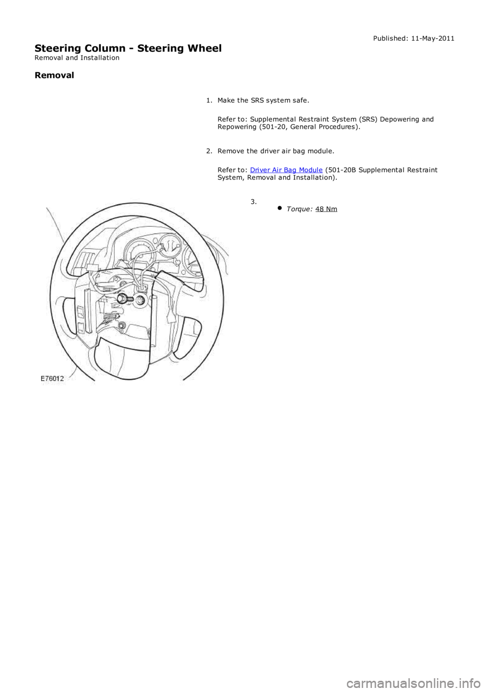
Make t he SRS s ys t em s afe.
Refer t o: Supplement al Res t raint Sys tem (SRS) Depowering and
Repowering (501-20, General Procedures ).
1.
Remove t he dri ver air bag modul e.
Refer t o: Dri ver Ai r Bag Modul e (501-20B Supplement al Res t raint
Syst em, Removal and Ins tall ati on).
2.
T orque: 48 Nm 3.
Page 585 of 3229

Publi s hed: 11-May-2011
Steering Column Switches - Steering Column Switches
Des cript ion and Operat ion
COMPONENT LOCATION
ItemPart NumberDescription
1-Speed cont rol s wit ches2-St eering column cas e containi ng the mult ifunct ion s wit ches and cl ocks pring
3-Audio control swit ches
OVERVIEW
The winds hield wiper s wit ch is l ocat ed in the right -hand-s ide of t he cas e and retai ned wit h 2 s crews . The s wit ch isconnected t o t he mai n harness vi a a connect or at the back of the s wi tch. The s wit ch cont rols the followi ng functi ons :
W i nds hiel d wi per i nt ermit tent s low and fas t speedW i nds hiel d wi per fli ck wipeW i nds hiel d was h/wi peRear was h/wipeInt ermit tent delay s electi on.
The t urn s ignal indicator s wit ch is locat ed i n t he left -hand-si de of the cas e and ret ained wi th 2 s crews . The swi tch i sconnected t o t he mai n harness vi a a connect or on the back of t he swit ch. The s wit ch cont rol s the foll owing funct ions:
Left / right turn s ignal operati onHigh / low beam operati onHeadl amp flas hTri p comput er functi on s el ect ion (i f fit t ed).
The t rip but t on allows the driver to cycle t hough an opti on menu and als o reset t ri p cycl e mi leage cal cul ati ons . The t ripcomput er informat ion i s dis played in the i nst rument clus ter mes s age cent er (high line ins trument cl us t er onl y).
Steering wheel mount ed s wit ches on the right -hand-s ide of t he dri ver's ai rbag, cont rol the audi o and tel ephone funct ions.Swit ches on the l eft -hand-s ide of t he dri ver's ai rbag control t he s peed cont rol functi ons .
The clocks pri ng is locat ed i n the front of t he cas e and retai ned wit h four s crews . The clocks pri ng engages i n s lots in t hes teeri ng wheel bos s and t urns wi th the rotat ion of t he s teeri ng wheel. The clocks pring incorporat es a t ang which cancelst he turn s ignal indicators when the st eering wheel i s rot ated.For addit ional informat ion, refer t o: Air Bag and Safet y Belt Pretens ioner Supplement al Res traint Syst em (SRS) (501-20BSuppl ement al Rest rai nt Sys tem, Des cri pti on and Operati on).
CONTROL DIAGRAM
• NOTE: A = Hardwi red; D = Hi gh s peed CAN bus , O = LIN bus
Page 1078 of 3229
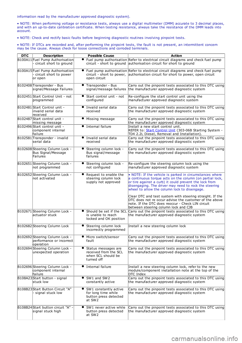
informat ion read by the manufact urer approved diagnos t ic s ys tem).
• NOTE: W hen performing volt age or res is t ance t est s , always use a digi tal mult imeter (DMM) accurat e t o 3 decimal places,and wit h an up-to-dat e cali brati on cert ificat e. W hen t est ing res is tance, al ways take t he res i st ance of t he DMM leads int oaccount.
• NOTE: Check and recti fy bas ic faul ts before beginni ng diagnos t ic rout ines i nvol vi ng pinpoint t es t s.
• NOTE: If DTCs are recorded and, aft er performi ng the pi npoi nt tes ts , t he fault i s not pres ent , an i nt ermit tent concernmay be t he cause. Always check for loos e connecti ons and corroded t ermi nal s.
DT CDescriptionPossible CauseAction
B100A11Fuel Pump Authori s at ion- ci rcuit s hort t o groundFuel pump aut horis at ioncircui t - short to groundRefer to el ect ri cal circui t diagrams and check fuel pumpaut horis at ion circui t for s hort t o ground
B100A15Fuel Pump Authori s at ion- ci rcuit s hort t o poweror open
Fuel pump aut horis at ioncircui t - short to power,open circuit
Refer to el ect ri cal circui t diagrams and check fuel pumpaut horis at ion circui t for s hort t o power, open circuit
B102408Trans ponder - Buss i gnal/Mes sage Fail uresTrans ponder - Buss ignal/mes sage failuresCarry out t he pinpoint t est s as s ociat ed t o t hi s DTC us ingthe manufact urer approved di agnos t ic s yst em
B102451St art Control Uni t - notprogrammedStart cont rol unit - notconfiguredRe-configure the s t art control unit us i ng themanufact urer approved diagnos t ic s ys tem
B102481St art Control uni t -i nval id s eri al dat arecei ved
Invali d s eri al dat areceivedCarry out t he pinpoint t est s as s ociat ed t o t hi s DTC us ingthe manufact urer approved di agnos t ic s yst em
B102487St art control unit -mis s ing mes s ageMi ss ing mess ageCarry out t he pinpoint t est s as s ociat ed t o t hi s DTC us ingthe manufact urer approved di agnos t ic s yst emB102496St art control unit -component i nternalfail ure
Int ernal fai lureIns tal l a new s tart cont rol unit .REFER t o: Start Cont rol Unit (303-06B St art ing Syst em -TD4 2.2L Di es el, Removal and Ins t al lat ion).
B102581Trans ponder - i nval ids eri al dat aInvali d s eri al dat areceivedCarry out t he pinpoint t est s as s ociat ed t o t hi s DTC us ingthe manufact urer approved di agnos t ic s yst em
B102608St eering Col umn Lock -Bus Si gnal /Mes s ageFail ures
Steering column lock -Bus s ignal/mes sagefai lures
Carry out t he pinpoint t est s as s ociat ed t o t hi s DTC us ingthe manufact urer approved di agnos t ic s yst em
B102651St eering Col umn Lock -not programmedSteering column lock -not configuredRe-configure the s t eering column lock us ing t hemanufact urer approved diagnos t ic s ys tem
B102652St eering Col umn Lock -not acti vat edReques t t o enabl e t hes teering column l ocks uppl y not approved
• NOTE: If t he vehi cle i s parked in ci rcums tances wherea cont inuous torque act s on t he column (on part ial lock,or t ire agains t a curb) i t could prevent t he l ock fromdi s engaging. The dri ver may need t o rock the s t eeringwheel t o all ow t he col umn l ock t o di sengage.
Clear DTC and tes t s yst em wit h s teeri ng s traight. If t heDTC does not re occur advis e t he cus t omer of t he abovenot e. If t he DTC does reoccur - Check LIN ci rcuitbet ween s teeri ng column l ock and CJB
B102671St eering Col umn Lock -actuat or st uckShoul d be s et if t he SCLis unable to reachlocked and OK pos it ion
Carry out t he pinpoint t est s as s ociat ed t o t hi s DTC us ingthe manufact urer approved di agnos t ic s yst em
B102682St eering Col umn LockSteering column lockincorrect ly programmedIns tal l a new s teering column lock
B102692St eering Col umn Lock -performance or i ncorrectoperat ion
Mi cro s wit ch/s ens orfaul tCarry out t he pinpoint t est s as s ociat ed t o t hi s DTC us ingthe manufact urer approved di agnos t ic s yst em
B102694St eering Col umn Lock -unexpect ed operati onStat us mes s ages arereceived from the SCLwhen SCL s houl d bet urned off
Carry out t he pinpoint t est s as s ociat ed t o t hi s DTC us ingthe manufact urer approved di agnos t ic s yst em
B102696St eering Col umn Lock -component i nternalfail ure
Int ernal fai lureIns tal l a new s teering column lock, refer to the newmodul e/component i ns t allat ion not e at t he top of t heDTC IndexB108A23St art butt on - s ignals t uck l owSW 1 and SW 2cons t ant ly act iveCarry out t he pinpoint t est s as s ociat ed t o t hi s DTC us ingthe manufact urer approved di agnos t ic s yst em
B108B23St art But ton Ci rcuit "A"- s i gnal s tuck l owSW 1 cons tant ly acti vefor l ong ti me whi lebutt on pres s detect edat SW 2
Carry out t he pinpoint t est s as s ociat ed t o t hi s DTC us ingthe manufact urer approved di agnos t ic s yst em
B108B24St art butt on circui t "A" -s i gnal s tuck highSW 1 never act ive whi lebutt on pres s detect edat SW 2
Carry out t he pinpoint t est s as s ociat ed t o t hi s DTC us ingthe manufact urer approved di agnos t ic s yst em
Page 1776 of 3229
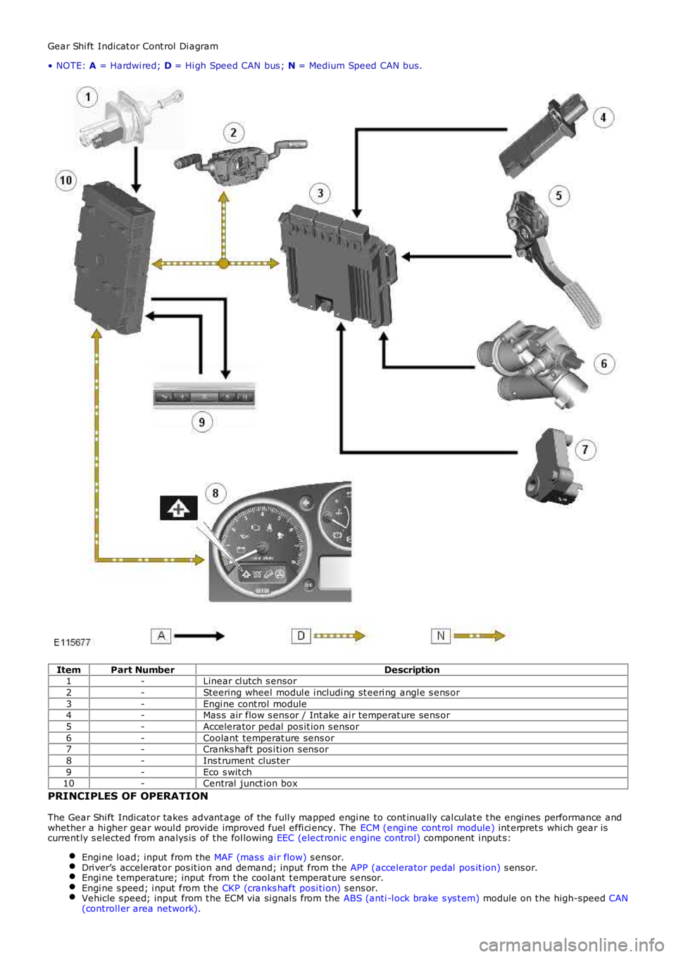
Gear Shi ft Indicat or Cont rol Di agram
• NOTE: A = Hardwi red; D = Hi gh Speed CAN bus ; N = Medium Speed CAN bus.
ItemPart NumberDescription1-Linear cl utch s ensor
2-Steering wheel modul e i ncludi ng st eeri ng angl e s ens or
3-Engi ne cont rol module4-Mas s air flow s ens or / Int ake ai r temperat ure sens or
5-Accelerator pedal pos it ion s ensor
6-Coolant temperat ure sens or7-Cranks haft pos i ti on s ens or
8-Ins t rument clus ter
9-Eco s wit ch10-Central junct ion box
PRINCIPLES OF OPERATION
The Gear Shi ft Indicat or takes advant age of the full y mapped engi ne to cont inually cal culat e t he engi nes performance andwhether a hi gher gear woul d provide improved fuel effi ci ency. The ECM (engi ne cont rol module) int erpret s whi ch gear iscurrent ly s elected from analys is of t he fol lowing EEC (elect ronic engine control) component i nput s:
Engi ne load; input from the MAF (mas s ai r flow) s ens or.Dri ver’s accelerat or pos it ion and demand; input from the APP (accelerator pedal pos it ion) s ens or.Engi ne t emperature; input from t he cool ant t emperat ure s ensor.Engi ne s peed; i nput from the CKP (cranks haft posi ti on) s ens or.Vehicle s peed; input from t he ECM via si gnal s from the ABS (anti -l ock brake s ys t em) module on t he high-speed CAN(controll er area network).
Page 1868 of 3229
Publi s hed: 11-May-2011
Information and Entertainment System - Audio System
Des cript ion and Operat ion
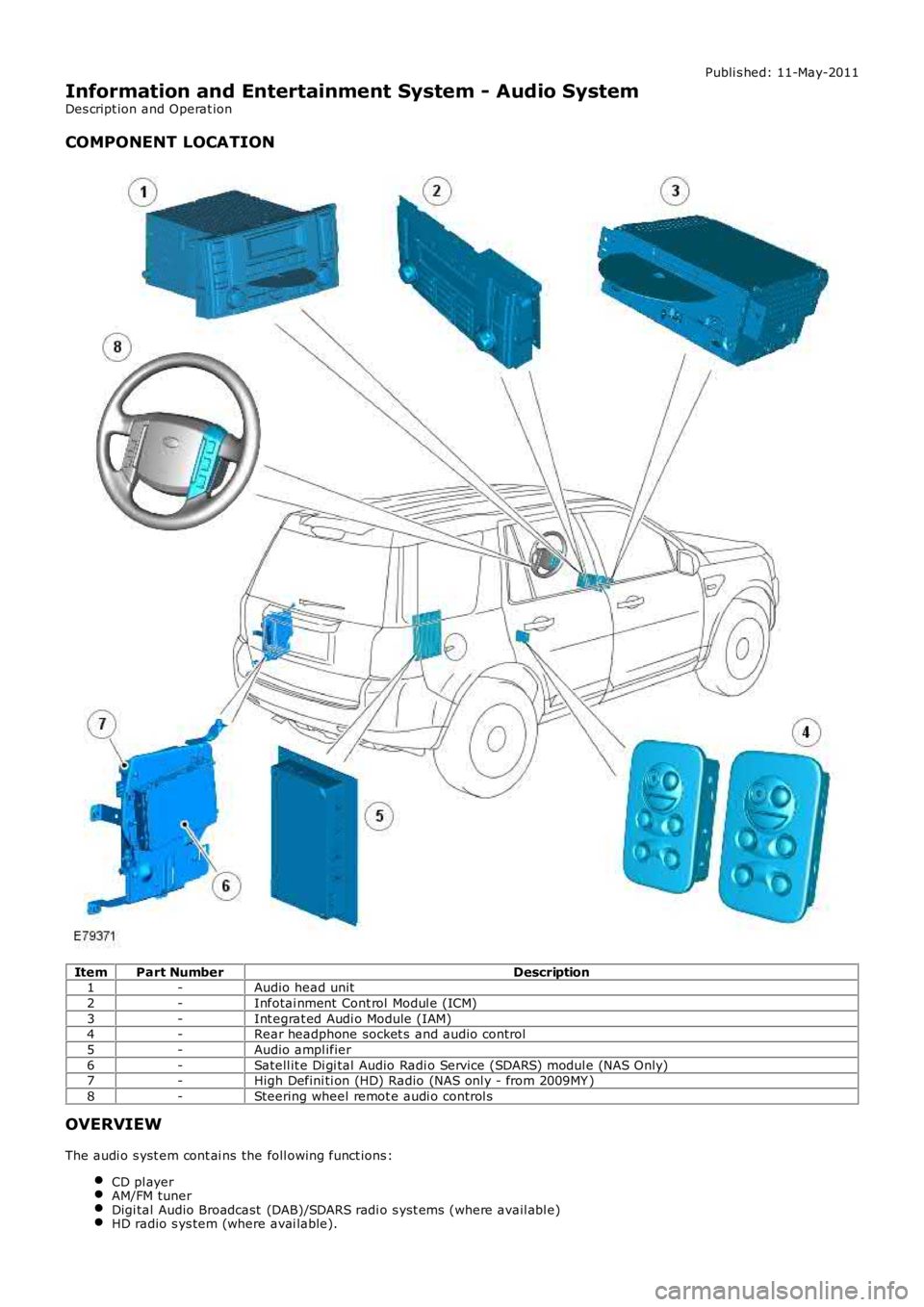
COMPONENT LOCATION
ItemPart NumberDescription1-Audio head unit
2-Infotai nment Cont rol Modul e (ICM)
3-Int egrat ed Audi o Module (IAM)4-Rear headphone socket s and audio control
5-Audio ampl ifier
6-Satell it e Di gi tal Audio Radi o Service (SDARS) modul e (NAS Only)7-High Defini ti on (HD) Radio (NAS onl y - from 2009MY )
8-Steering wheel remot e audi o control s
OVERVIEW
The audi o s yst em cont ai ns the foll owing funct ions :
CD pl ayerAM/FM tunerDigi tal Audio Broadcast (DAB)/SDARS radi o s yst ems (where avail abl e)HD radio s ys tem (where avai lable).