2006 LAND ROVER FRELANDER 2 steering wheel
[x] Cancel search: steering wheelPage 2725 of 3229

Contents
5
R
ENGINE COOLANT CHECK ............................ 163
BRAKE AND CLUTCH FLUID CHECK ............. 165
POWER STEERING FLUID CHECK ................ 166
WASHER FLUID CHECK ................................ 167
TECHNICAL SPECIFICATIONS ...................... 169
Vehicle battery
BATTERY WARNING SYMBOLS ................... 171
BATTERY CARE ............................................ 171
USING BOOSTER CABLES ............................ 173
CHARGING THE VE HICLE BATTERY ............. 174
CHANGING THE VE HICLE BATTERY ............. 174
Wheels and tyres
GENERAL INFORMATION ............................. 176
TYRE CARE ................................................... 177
USING WINTER TYRES................................. 183
CHANGING A ROAD WHEEL ......................... 183
TYRE REPAIR KIT ......................................... 187
USING SNOW CHAINS.................................. 192
TYRE GLOSSARY.......................................... 193
TECHNICAL SPECIFICATIONS ...................... 194
Fuses
FUSE BOX LOCATIONS ................................. 195
CHANGING A FUSE ....................................... 195
FUSE SPECIFICATION CHART....................... 196
Emergency equipment
HAZARD WARNING FLASHERS .................... 204
WARNING TRIANGLE ................................... 204
Status after a collision
DRIVING AFTER A COLLISION...................... 205
INSPECTING SAFETY SYSTEM COMPONENTS ...
206
Vehicle recovery
TOWING POINTS .......................................... 207
LASHING POINTS ......................................... 208
TRANSPORTING THE VEHICLE..................... 208
TOWING THE VEHICLE ON FOUR WHEELS .. 208
Vehicle identification
VEHICLE IDENTIFICATION PLATE................. 210
VEHICLE IDENTIFI CATION NUMBER (VIN) ... 210
VEHICLE BUILD DATE PLATE ....................... 210
Technical specifications
ENGINE SPECIFICATIONS ............................ 211
WEIGHTS...................................................... 212
DIMENSIONS................................................ 213
Type approval
Declarations of conformity ........................... 215
Audio introduction
RADIO RECEPTION....................................... 218
Audio unit overview
AUDIO UNIT OVERVIEW............................... 219
Audio unit operation
ON OR OFF CONTROL .................................. 223
VOLUME CONTROL ...................................... 223
AUDIO CONTROL ......................................... 223
WAVEBAND BUTTON ................................... 224
AUTOSTORE CONTROL ................................ 225
STATION PRESET BUTTONS ........................ 226
TRAFFIC INFORMATION CONTROL .............. 226
Audio unit menus
RADIO DATA SYSTEM (RDS) ....................... 228
REGIONAL MODE (REG) .............................. 228
ENHANCED OTHER NETWORK (RDS-EON).. 229
ALTERNATIVE FREQUENCIES ...................... 229
NEWS BROADCASTS ................................... 230
PRIORITY PROGRAMME TYPE (PTY) .......... 231
RESETTING THE AUDIO UNIT ...................... 233
Digital audio broadcasting
GENERAL INFORMATION ............................. 234
AUDIO CONTROLS ....................................... 235
DISPLAY OPTIONS ....................................... 236
CHANNEL AUTOMATIC TUNING................... 236
CHANNEL OPTIONS ..................................... 236
PRESET BUTTONS ....................................... 238
SETTINGS..................................................... 240
Compact disc player
LOADING COMPACT DISCS ......................... 245
EJECTING COMPACT DISCS ........................ 246
EJECTING MULTIPLE CO MPACT DISCS....... 246
COMPACT DISC SELECTION ........................ 246
COMPACT DISC PLAYBACK ......................... 246
Page 2732 of 3229
12
Quick start
L
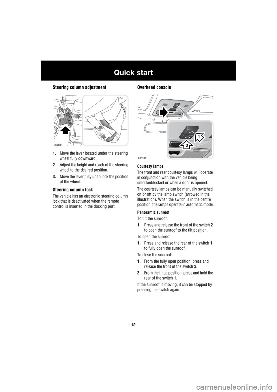
Steering column adjustment
1. Move the lever located under the steering
wheel fully downward.
2. Adjust the height and reach of the steering
wheel to the desired position.
3. Move the lever fully up to lock the position
of the wheel.
Steering column lock
The vehicle has an electronic steering column
lock that is deactivated when the remote
control is inserted in the docking port.
Overhead console
Courtesy lamps
The front and rear cour tesy lamps will operate
in conjunction with the vehicle being
unlocked/locked or when a door is opened.
The courtesy la mps can be manually switched
on or off by the lamp switch (arrowed in the
illustration). When the switch is in the centre
position, the lamps opera te in automatic mode.
Panoramic sunroof
To tilt the sunroof:
1. Press and release the front of the switch 2
to open the sunroof to the tilt position.
To open the sunroof:
1. Press and release the rear of the switch 1
to fully open the sunroof.
To close the sunroof:
1. From the fully open position, press and
release the front of the switch 2.
2. From the tilted positi on, press and hold the
rear of the switch 1.
If the sunroof is moving, it can be stopped by
pressing the switch again.
E83192
E83193
1
2
Page 2743 of 3229
23
Quick start
R
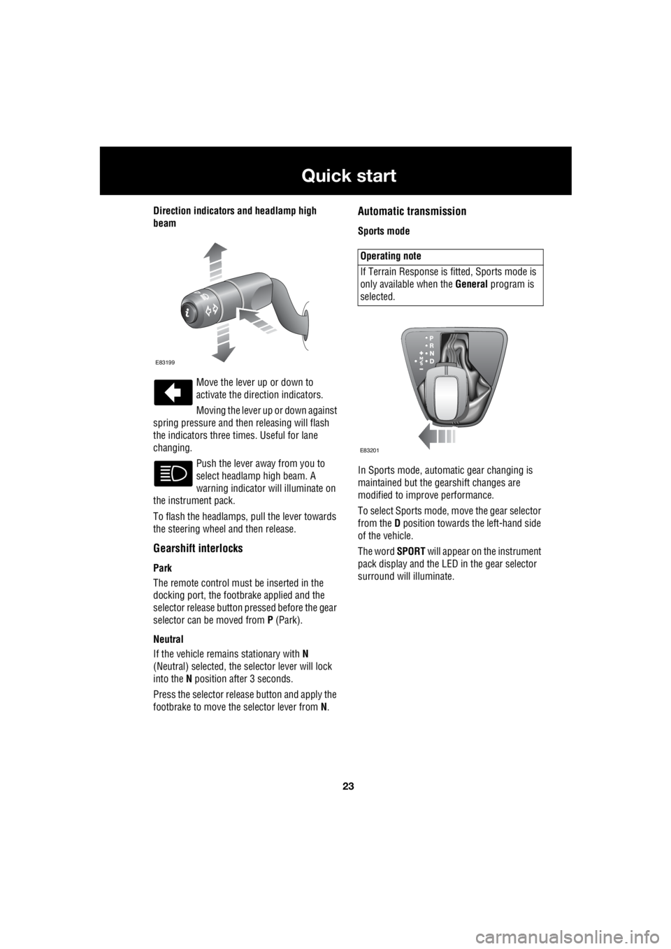
Direction indicators and headlamp high
beam
Move the lever up or down to
activate the direction indicators.
Moving the lever up or down against
spring pressure and then releasing will flash
the indicators three times. Useful for lane
changing.
Push the lever away from you to
select headlamp high beam. A
warning indicator will illuminate on
the instrument pack.
To flash the headlamps, pull the lever towards
the steering wheel and then release.
Gearshift interlocks
Park
The remote control must be inserted in the
docking port, the footbrake applied and the
selector release button pr essed before the gear
selector can be moved from P (Park).
Neutral
If the vehicle remains stationary with N
(Neutral) selected, the selector lever will lock
into the N position after 3 seconds.
Press the selector rele ase button and apply the
footbrake to move the selector lever from N.
Automatic transmission
Sports mode
In Sports mode, automatic gear changing is
maintained but the gearshift changes are
modified to improve performance.
To select Sports mode, move the gear selector
from the D position towards the left-hand side
of the vehicle.
The word SPORT will appear on the instrument
pack display and the LED in the gear selector
surround will illuminate.
E83199
Operating note
If Terrain Response is fi tted, Sports mode is
only available when the General program is
selected.
E83201
Page 2749 of 3229
29
Quick start
R
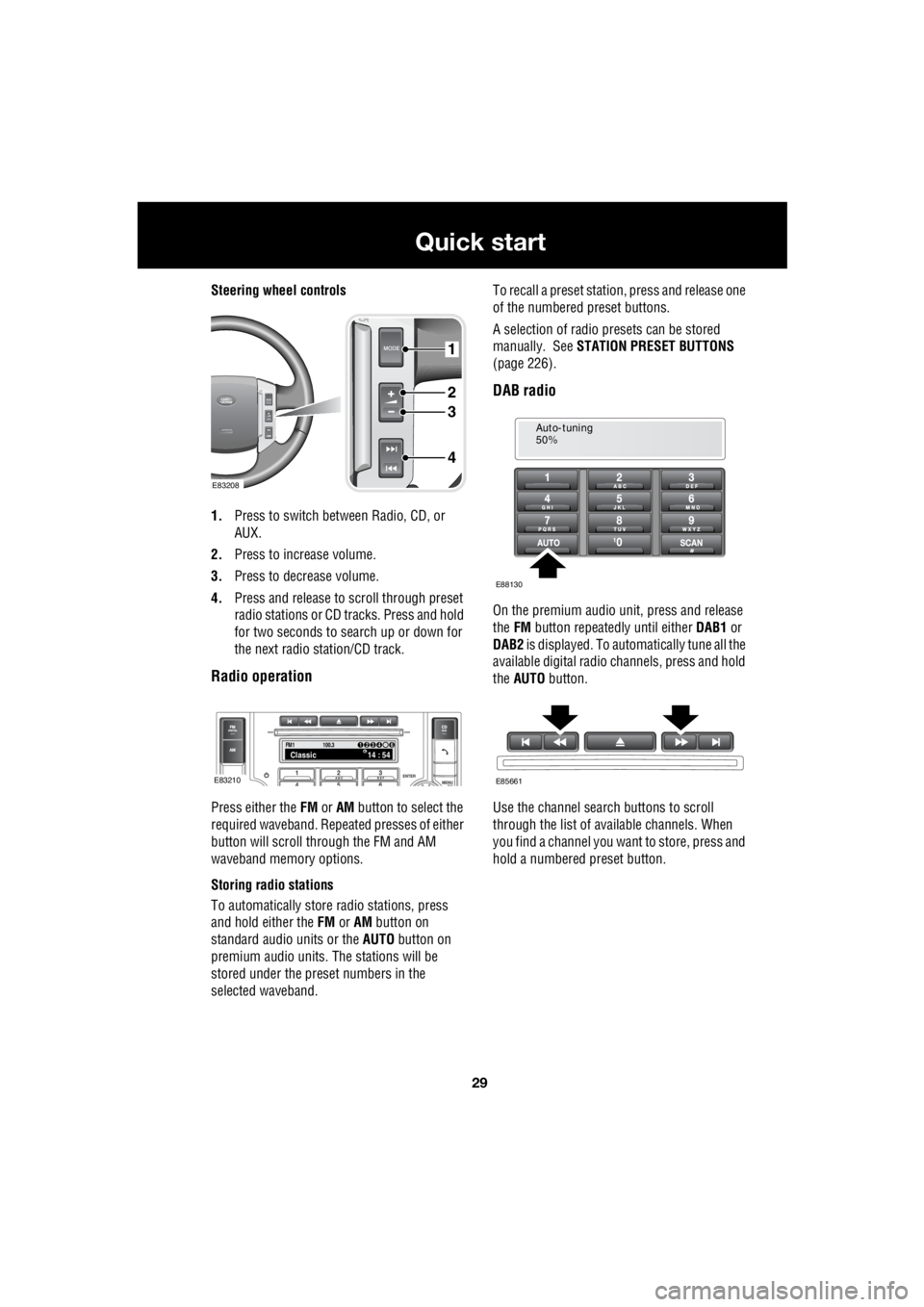
Steering wheel controls
1. Press to switch between Radio, CD, or
AUX.
2. Press to increase volume.
3. Press to decrease volume.
4. Press and release to scroll through preset
radio stations or CD tracks. Press and hold
for two seconds to search up or down for
the next radio station/CD track.
Radio operation
Press either the FM or AM button to select the
required waveband. Repeat ed presses of either
button will scroll through the FM and AM
waveband memory options.
Storing radio stations
To automatically store radio stations, press
and hold either the FM or AM button on
standard audio units or the AUTO button on
premium audio units. The stations will be
stored under the preset numbers in the
selected waveband. To recall a preset stati
on, press and release one
of the numbered preset buttons.
A selection of radio pr esets can be stored
manually. See STATION PRESET BUTTONS
(page 226).
DAB radio
On the premium audio unit, press and release
the FM button repeatedly until either DAB1 or
DAB2 is displayed. To auto matically tune all the
available digital radio channels, press and hold
the AUTO button.
Use the channel search buttons to scroll
through the list of available channels. When
you find a channel you want to store, press and
hold a numbered preset button.
1
2
3
4
E83208
FM114 : 54Classic1234 6
100.3
E83210
Auto-tuning
50%
E88130
E85661
Page 2752 of 3229
32
Quick start
L
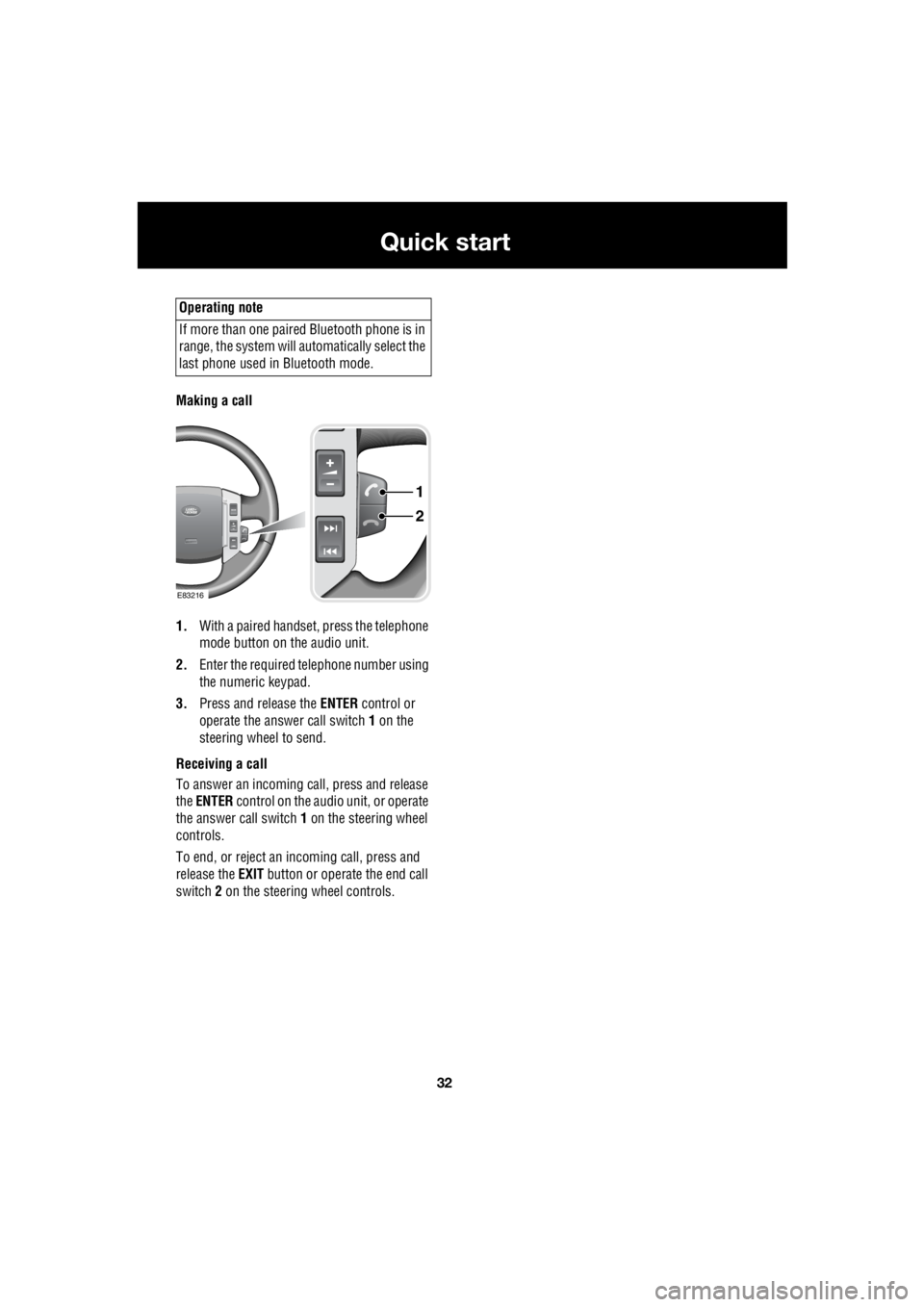
Making a call
1. With a paired handset, press the telephone
mode button on the audio unit.
2. Enter the required te lephone number using
the numeric keypad.
3. Press and release the ENTER control or
operate the answer call switch 1 on the
steering wheel to send.
Receiving a call
To answer an incoming call, press and release
the ENTER control on the audio unit, or operate
the answer call switch 1 on the steering wheel
controls.
To end, or reject an incoming call, press and
release the EXIT button or operate the end call
switch 2 on the steering wheel controls.
Operating note
If more than one paired Bluetooth phone is in
range, the system will automatically select the
last phone used in Bluetooth mode.
1
2
E83216
Page 2757 of 3229
37
Introduction
R
DATA RECORDING
Service data recording
Service data recorders in your vehicle are
capable of collecting and storing diagnostic
information about your vehicle. This potentially
includes information about the performance or
status of various syst ems and modules in the
vehicle such as engine, throttle, steering or
brakes.
In order to properly di agnose and service your
vehicle, Land Rover a nd service and repair
facilities may access vehicle diagnostic
information through a direct connection to
your vehicle.
Event data recording
Event data recorders are capable of collecting
and storing data during a crash or near-crash
event. The recorded information may assist in
the investigation of such an event. The
modules may record information about both
the vehicle and the oc cupants, potentially
including information such as:
• How various systems in your vehicle were
operating.
• Whether or not the driver and passenger
seat belts were buckled.
• How far, if at all, the driver was depressing
the accelerator and/or the brake pedal.
• How fast the vehicle was travelling.
• Where the driver was positioning the
steering wheel.
To access this information special equipment
must be connected directly to the recording
modules. Land Rover do not access event data
recorder information without obtaining
consent, unless pursuan t to court order or
where required by law enforcement, other
government authorities or third parties acting
with lawful authority. Other parties may seek to access the
information independe ntly of Land Rover.
DISABILITY MODIFICATIONS
Occupants with disabili ties which may require
modification of the vehi cle must contact a Land
Rover Dealer/Authorised Repairer before any
modifications are made.
PARTS AND ACCESSORIES
WARNINGS
The fitting of non-approved parts and
accessories, or the carrying out of
non-approved alterations or
conversions, may be dangerous and could
affect the safety of th e vehicle and occupants
and also invalidate the terms and conditions of
the vehicle warranty.
Land Rover will not accept any liability
for death, personal injury or damage to
property which may occur as a direct
result of fitment of non-approved accessories
or the carrying out of non-approved
conversions to La nd Rover vehicles.
Land Rover strongly advise against
making any modifications to the
suspension or steering system. This
could seriously affe ct the handling and
stability of the vehicle leading to loss of control
or roll-over.
Page 2759 of 3229
39
Introduction
R
Airbag system
To prevent malfunction of the airbag system
always consult a Land Rover Dealer/
Authorised Repairer before fitting any of the
following:
• Electronic equipment such as a mobile
phone, two-way radio or in-car
entertainment system.
• Accessories attached to the front of the
vehicle.
• Any modification to the front of the vehicle.
• Any modification involving the removal or
repair of any wiring or component in the
vicinity of any of the airbag system
components, including the steering wheel,
steering column, instrument or facia
panels.
• Any modification to th e facia panels or
steering wheel.
After-sales service
The After Sales Parts service is of paramount
importance, both in th e UK and across the
world. In the UK there are over 100 authorised
Land Rover Dealers/Authorised Repairers, all
computer linked for rapid ordering of parts and
accessories.
In addition, with franch ised representation in
over 100 countries worldwide, Land Rover are
able to support your vehicle wherever you go.
Travelling abroad
In certain countries, it is a legal requirement to
fit parts made to the vehicle manufacturers'
specification.
Owners should ensure that any parts or
accessories fitted to the vehicle while travelling
abroad will also conform to the legal
requirements of their own country when they
return home.
WARNING
The components that make up the
airbag system are sensitive to
electrical or physical interference,
either of which coul d easily damage the
system and cause inadvertent operation or a
malfunction of th e airbag module.
E84193
Page 2767 of 3229
47
Seats
R
SeatsSITTING IN THE CORRECT POSITION
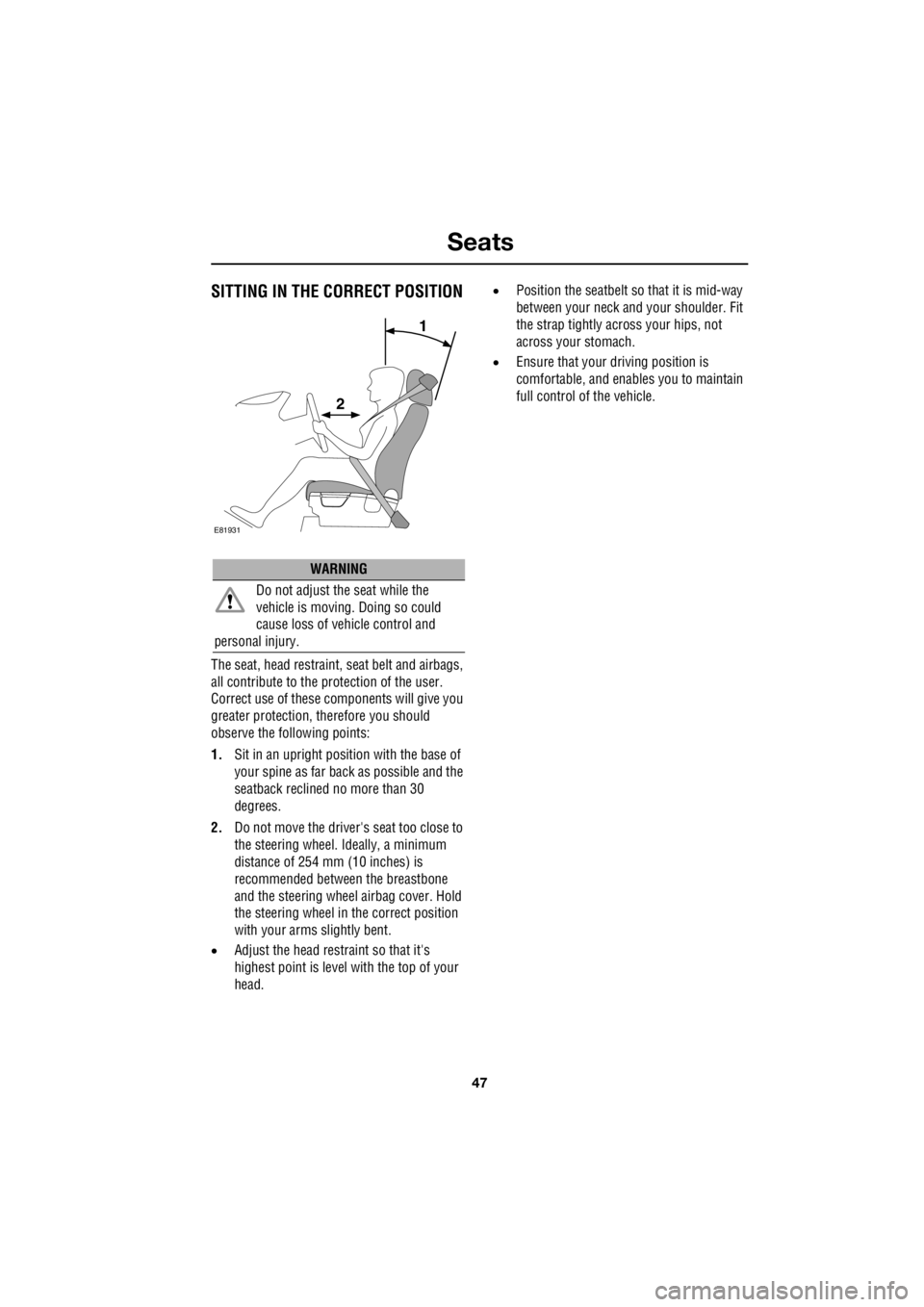
The seat, head restraint, seat belt and airbags,
all contribute to the protection of the user.
Correct use of these components will give you
greater protection, therefore you should
observe the following points:
1. Sit in an upright position with the base of
your spine as far back as possible and the
seatback reclined no more than 30
degrees.
2. Do not move the driver's seat too close to
the steering wheel. Ideally, a minimum
distance of 254 mm (10 inches) is
recommended betwee n the breastbone
and the steering wheel airbag cover. Hold
the steering wheel in the correct position
with your arms slightly bent.
• Adjust the head restraint so that it's
highest point is level with the top of your
head. •
Position the seatbelt so that it is mid-way
between your neck an d your shoulder. Fit
the strap tightly across your hips, not
across your stomach.
• Ensure that your driving position is
comfortable, and enab les you to maintain
full control of the vehicle.
WARNING
Do not adjust the seat while the
vehicle is moving. Doing so could
cause loss of vehicle control and
personal injury.
1
E81931
2