2006 LAND ROVER FRELANDER 2 steering wheel
[x] Cancel search: steering wheelPage 528 of 3229
Publi s hed: 11-May-2011
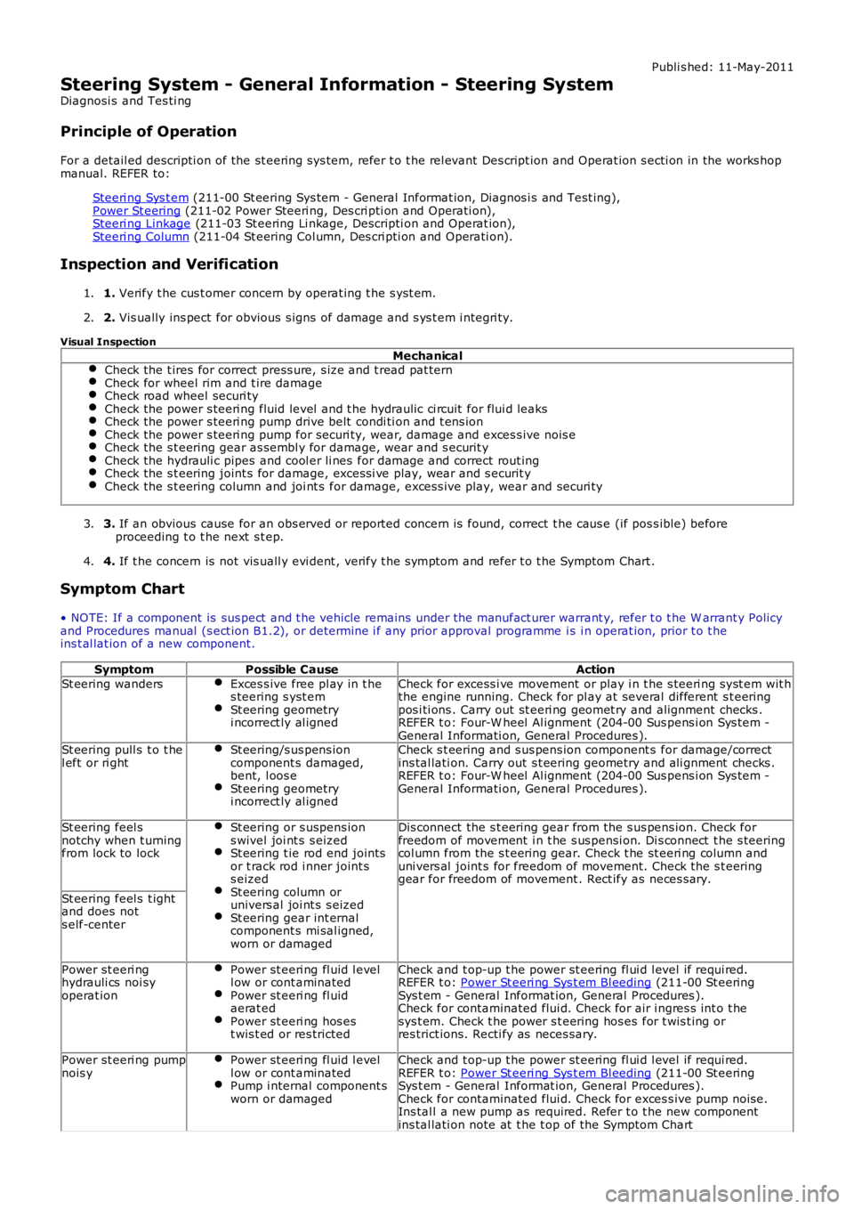
Steering System - General Information - Steering System
Diagnosi s and Tes ti ng
Principle of Operation
For a detail ed descripti on of the st eering sys tem, refer t o t he rel evant Des cript ion and Operat ion s ecti on in the works hopmanual. REFER to:
Steeri ng Sys t em (211-00 St eering Sys tem - General Informat ion, Diagnos i s and Test ing),Power St eering (211-02 Power Steeri ng, Des cri pti on and Operati on),Steeri ng Linkage (211-03 St eering Li nkage, Descripti on and Operat ion),Steeri ng Column (211-04 St eering Col umn, Des cri pti on and Operati on).
Inspection and Verification
1. Verify t he cus t omer concern by operat ing t he s yst em.1.
2. Vis ually ins pect for obvious s igns of damage and s ys t em i ntegri ty.2.
Visual Inspection
MechanicalCheck the t ires for correct press ure, s ize and t read pat ternCheck for wheel rim and t ire damageCheck road wheel securi tyCheck the power s teeri ng fluid level and t he hydraulic ci rcuit for flui d leaksCheck the power s teeri ng pump drive belt condi ti on and t ens ionCheck the power s teeri ng pump for securi ty, wear, damage and exces s ive nois eCheck the s t eering gear as sembl y for damage, wear and s ecurit yCheck the hydrauli c pipes and cool er li nes for damage and correct rout ingCheck the s t eering joint s for damage, excess i ve play, wear and s ecurit yCheck the s t eering column and joi nt s for damage, exces s ive play, wear and securi ty
3. If an obvious cause for an obs erved or report ed concern is found, correct t he caus e (if pos s ible) beforeproceeding t o t he next s t ep.3.
4. If t he concern is not vis uall y evi dent , verify t he s ymptom and refer t o t he Symptom Chart .4.
Symptom Chart
• NOTE: If a component is sus pect and t he vehicle remains under the manufact urer warrant y, refer t o t he W arrant y Policyand Procedures manual (s ect ion B1.2), or determine i f any prior approval programme is i n operat ion, prior t o t heins t al lat ion of a new component.
SymptomPossible CauseAction
St eering wandersExces s ive free pl ay in t hes teering s yst emSt eering geometryi ncorrect ly al igned
Check for excess i ve movement or play i n t he s teeri ng s yst em wit hthe engine running. Check for pl ay at several different s t eeringpos i ti ons . Carry out st eeri ng geomet ry and alignment checks .REFER t o: Four-W heel Al ignment (204-00 Sus pens i on Sys t em -General Informati on, General Procedures ).St eering pull s t o t hel eft or ri ghtSt eering/s us pens ioncomponent s damaged,bent, l oos eSt eering geometryi ncorrect ly al igned
Check s t eering and s us pens ion component s for damage/correctins tal lati on. Carry out s t eering geometry and ali gnment checks .REFER t o: Four-W heel Al ignment (204-00 Sus pens i on Sys t em -General Informati on, General Procedures ).
St eering feel snotchy when t urningfrom lock to lock
St eering or s uspens ions wivel joi nt s s eizedSt eering t ie rod end jointsor t rack rod i nner joint ss eizedSt eering column orunivers al joi nt s s eizedSt eering gear int ernalcomponent s mi sal igned,worn or damaged
Dis connect the s t eering gear from the s us pens ion. Check forfreedom of movement i n t he s us pensi on. Di s connect t he s teeringcol umn from the s t eering gear. Check t he st eeri ng col umn anduni vers al joint s for freedom of movement. Check the s t eeringgear for freedom of movement . Rect ify as neces s ary.
St eering feel s t ightand does nots elf-center
Power st eeri nghydrauli cs noi syoperat ion
Power st eeri ng fl uid l evell ow or cont aminatedPower st eeri ng fl uidaerat edPower st eeri ng hos est wis t ed or res tricted
Check and t op-up t he power st eering fl ui d l evel if requi red.REFER t o: Power St eeri ng Sys t em Bl eeding (211-00 St eeringSys t em - General Informat ion, General Procedures ).Check for contaminated flui d. Check for air i ngres s int o t hesys t em. Check t he power s t eering hos es for t wis t ing orres trict ions. Recti fy as neces sary.
Power st eeri ng pumpnois yPower st eeri ng fl uid l evell ow or cont aminatedPump i nternal component sworn or damaged
Check and t op-up t he power st eering fl ui d l evel if requi red.REFER t o: Power St eeri ng Sys t em Bl eeding (211-00 St eeringSys t em - General Informat ion, General Procedures ).Check for contaminated flui d. Check for exces s ive pump noi se.Ins tal l a new pump as required. Refer t o t he new componentins tal lati on note at t he t op of the Sympt om Chart
Page 538 of 3229
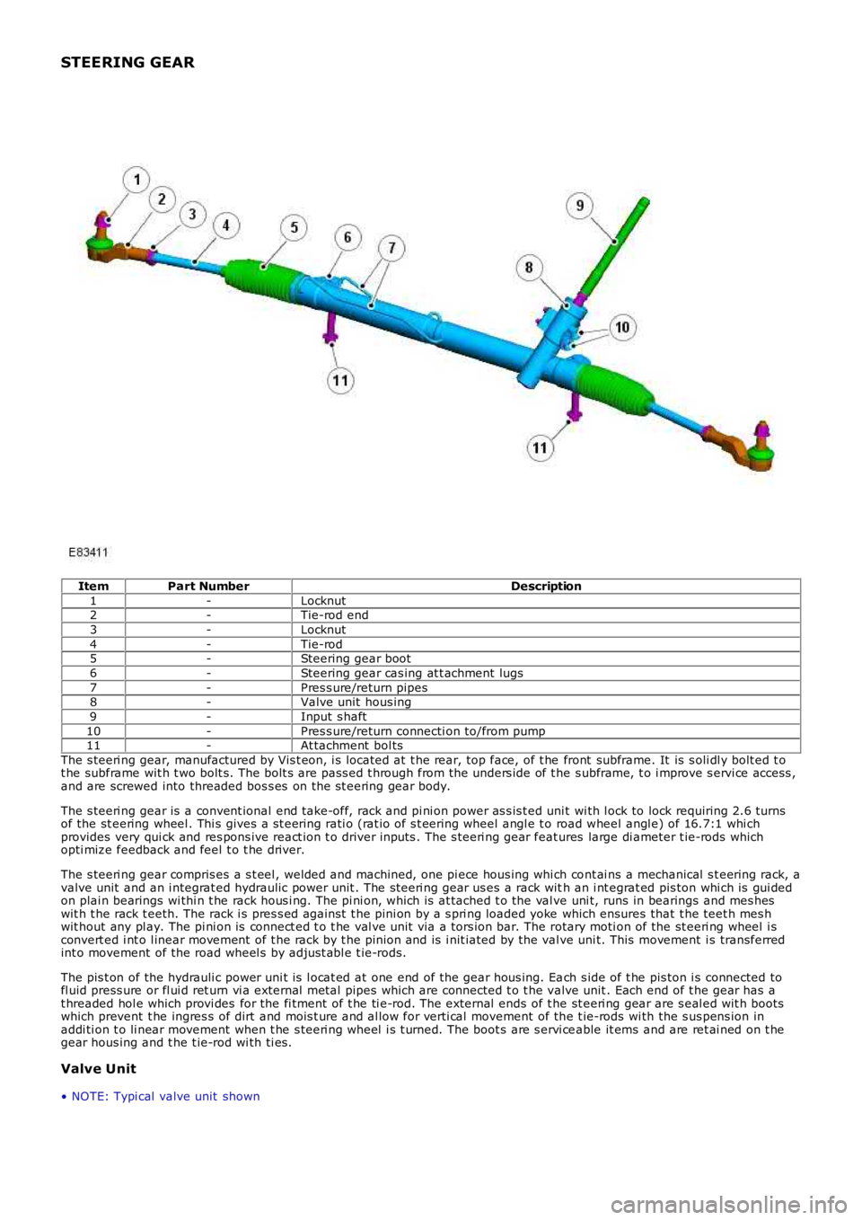
STEERING GEAR
ItemPart NumberDescription
1-Locknut2-Tie-rod end
3-Locknut
4-Tie-rod5-Steering gear boot
6-Steering gear cas ing at t achment lugs
7-Pres s ure/return pipes8-Valve unit hous ing
9-Input s haft
10-Pres s ure/return connecti on to/from pump11-At tachment bol ts
The s teeri ng gear, manufactured by Vis t eon, i s located at t he rear, top face, of t he front subframe. It is s oli dl y bolt ed t ot he subframe wit h t wo bolt s. The bolt s are pass ed t hrough from the unders ide of t he s ubframe, t o i mprove s ervi ce access ,and are screwed into threaded bos s es on the st eering gear body.
The s teeri ng gear is a convent ional end take-off, rack and pi ni on power as s is t ed unit wi th l ock to lock requiring 2.6 turnsof the st eering wheel . Thi s gives a s t eering rati o (rat io of s t eering wheel angl e t o road wheel angl e) of 16.7:1 whi chprovides very qui ck and res pons ive react ion t o driver inputs . The s teeri ng gear features large di ameter t ie-rods whichopti mize feedback and feel t o t he driver.
The s teeri ng gear compris es a s t eel , welded and machined, one pi ece hous ing whi ch cont ai ns a mechanical s t eering rack, avalve unit and an i ntegrat ed hydraulic power unit . The s teeri ng gear us es a rack with an i nt egrat ed pis ton whi ch is gui dedon plai n bearings wi thi n t he rack hous i ng. The pi ni on, whi ch is at tached t o the val ve uni t, runs in bearings and mes heswit h t he rack t eeth. The rack i s pres s ed agai nst t he pini on by a s pri ng loaded yoke which ensures that t he teet h mes hwit hout any pl ay. The pi ni on is connect ed t o t he val ve unit via a tors ion bar. The rotary moti on of the st eeri ng wheel i sconvert ed i nt o l inear movement of t he rack by t he pinion and is i nit iated by the valve uni t. This movement i s transferredint o movement of the road wheel s by adjus t abl e t ie-rods.
The pis t on of the hydrauli c power uni t is l ocat ed at one end of the gear hous ing. Each s ide of t he pis ton i s connected tofl uid press ure or fl ui d ret urn vi a external met al pipes which are connected t o t he valve unit . Each end of t he gear has at hreaded hol e which provi des for the fi tment of t he ti e-rod. The external ends of t he st eeri ng gear are s eal ed wit h bootswhich prevent t he ingres s of dirt and mois t ure and al low for verti cal movement of the t ie-rods wi th the s us pens ion inaddi ti on t o li near movement when t he s teeri ng wheel i s t urned. The boot s are s ervi ceable it ems and are ret ai ned on t hegear hous ing and t he t ie-rod wi th ti es .
Valve Unit
• NOTE: Typi cal valve unit shown
Page 540 of 3229
diamet er in i ts central sect ion. The smal ler diamet er allows the t ors ion bar t o t wist in res pons e t o t orque appli ed from t hes teeri ng wheel in relati on t o t he grip of the t yres on t he road surface. The pi nion s haft has machined t eet h on it s cent raldiamet er whi ch mat e wit h t eeth on the s t eering gear rack. A s lot , machi ned in t he upper end of t he pini on s haft mateswit h t he dog-t oot h on the i nput s haft . The pinion s haft l ocat es in the pi ni on housi ng and rot ates on bal l and roll erbearings .
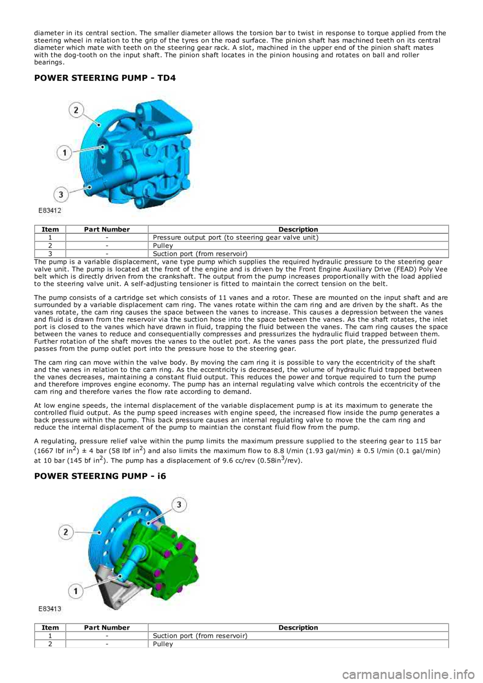
POWER STEERING PUMP - TD4
ItemPart NumberDescription1-Pres s ure out put port (t o s t eering gear val ve unit )
2-Pull ey
3-Sucti on port (from res ervoi r)The pump i s a vari abl e dis placement, vane t ype pump which s uppl ies t he required hydraulic pres sure t o the st eeri ng gearvalve unit . The pump is locat ed at t he front of t he engine and i s dri ven by the Front Engine Auxil iary Dri ve (FEAD) Poly Veebelt which i s direct ly driven from the cranks haft . The out put from t he pump i ncreas es proporti onall y wi th the l oad appl iedt o the st eeri ng val ve uni t. A s el f-adjus ti ng tens ioner is fit t ed to maint ai n t he correct t ens ion on the bel t.
The pump consi st s of a cart ridge s et which cons is t s of 11 vanes and a rot or. These are mount ed on t he input s haft and ares urrounded by a variable di spl acement cam ring. The vanes rotat e wit hin the cam ri ng and are driven by t he s haft. As thevanes rotat e, the cam ri ng caus es the space between t he vanes to increase. This causes a depres si on between t he vanesand fl uid i s drawn from t he res ervoir vi a t he suct ion hos e int o t he s pace between the vanes. As t he s haft rotat es , t he inl etport i s clos ed to the vanes which have drawn in fluid, t rapping t he fluid bet ween t he vanes . The cam ring caus es t he s pacebetween t he vanes to reduce and cons equenti ally compress es and pres s uri zes t he hydrauli c fl ui d t rapped between t hem.Furt her rotat ion of t he s haft moves the vanes t o the out let port . As t he vanes pas s t he port plat e, the pres s uri zed fl ui dpass es from the pump out let port into the press ure hose to the s t eering gear.
The cam ring can move wi thi n t he val ve body. By moving the cam ri ng it i s poss ibl e to vary t he eccentricit y of t he s haftand t he vanes i n rel ati on to the cam ri ng. As t he eccent rici ty i s decreased, t he volume of hydraulic flui d t rapped bet weent he vanes decreases , mai nt aining a cons t ant flui d output. This reduces t he power and torque required to turn t he pumpand t herefore improves engine economy. The pump has an int ernal regulati ng valve which controls t he eccentricit y of t hecam ring and t herefore vari es the flow rat e accordi ng to demand.
At low engi ne s peeds , the i nternal dis placement of the vari able di spl acement pump i s at it s maximum t o generate thecont rol led fluid out put. As t he pump s peed increas es wit h engine s peed, t he i ncreas ed flow ins ide t he pump generates aback press ure wit hin the pump. This back pres s ure causes an internal regul ati ng val ve to move t he the cam ri ng andreduce t he int ernal di spl acement of the pump to maint ian t he cons t ant flui d fl ow from the pump.
A regul ati ng, pres s ure reli ef val ve wit hin t he pump l imi ts the maxi mum press ure s uppl ied t o t he s teeri ng gear t o 115 bar
(1667 l bf in2) ± 4 bar (58 lbf i n2) and al so li mit s t he maximum fl ow t o 8.8 l/min (1.93 gal/min) ± 0.5 l /min (0.1 gal /min)
at 10 bar (145 bf i n2). The pump has a dis placement of 9.6 cc/rev (0.58i n3/rev).
POWER STEERING PUMP - i6
ItemPart NumberDescription
1-Sucti on port (from res ervoi r)
2-Pull ey
Page 552 of 3229
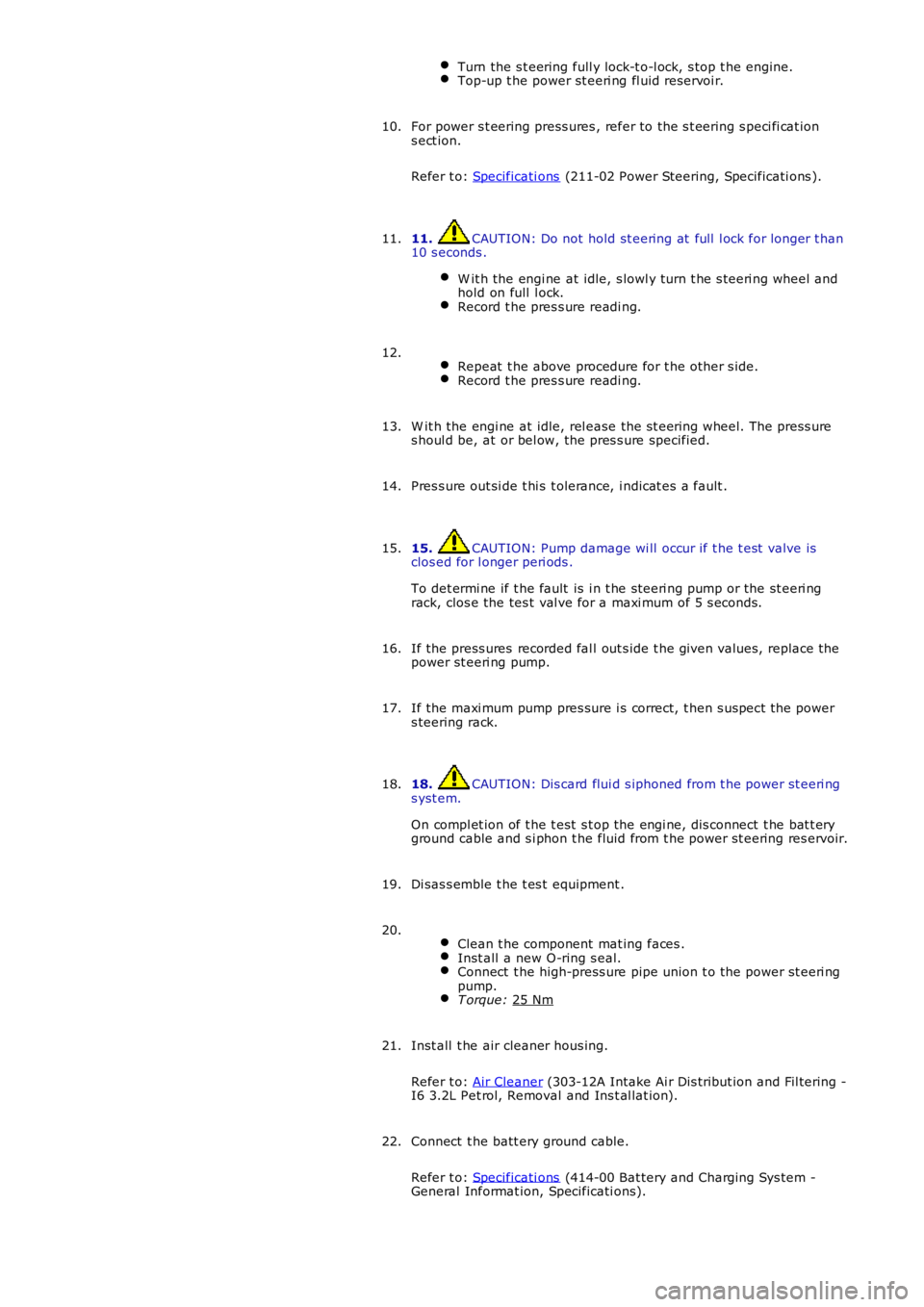
Turn the s t eering full y lock-t o-l ock, s top t he engine.
Top-up t he power st eeri ng fl uid reservoi r.
For power s t eering press ures , refer to the s t eering s peci fi cat ion
s ect ion.
Refer t o: Specificati ons (211-02 Power Steering, Specificati ons ).
10.
11. CAUTION: Do not hold st eering at full l ock for longer t han
10 s econds .
W it h the engi ne at idle, s lowl y turn t he s teeri ng wheel and
hold on full l ock. Record t he pres s ure readi ng.11.
Repeat t he above procedure for t he other s ide. Record t he pres s ure readi ng.12.
W it h the engi ne at idle, rel ease the s t eering wheel. The press ure
s houl d be, at or bel ow, the pres s ure specified.
13.
Pres s ure out si de t hi s t olerance, i ndicat es a fault .
14.
15. CAUTION: Pump damage wi ll occur if t he t est valve is
clos ed for l onger peri ods .
To det ermi ne if t he fault is i n t he st eeri ng pump or the st eeri ng
rack, clos e the tes t val ve for a maxi mum of 5 s econds.
15.
If the press ures recorded fal l out s ide t he given values, replace the
power st eeri ng pump.
16.
If the maxi mum pump pres sure i s correct, t hen s uspect the power
s teering rack.
17.
18. CAUTION: Dis card flui d s iphoned from t he power st eeri ng
s yst em.
On compl et ion of t he t est s t op the engi ne, dis connect t he bat t ery
ground cable and s i phon t he fluid from t he power st eering res ervoir.
18.
Di sas s emble t he t es t equipment .
19.
Clean t he component mat ing faces . Inst all a new O-ring s eal.
Connect t he high-press ure pipe union t o t he power st eeri ng
pump. T orque:
25 Nm 20.
Inst all t he air cleaner hous ing.
Refer t o: Air Cleaner (303-12A Intake Ai r Dis tribut ion and Fil tering -
I6 3.2L Pet rol, Removal and Ins t al lat ion).
21.
Connect t he batt ery ground cable.
Refer t o: Specificati ons (414-00 Bat tery and Charging Sys tem -
General Informat ion, Specificati ons).
22.
Page 560 of 3229
Publi s hed: 11-May-2011
Power Steering - Steering Gear
Removal and Inst all ati on
Removal
1. W ARNING: Make sure t o s upport the vehicle wit h axle
s tands .
Rais e and s upport t he vehi cl e.
1.
Remove t he front road wheels and t ires.
Refer t o: W heel and Ti re (204-04 W heel s and Tires, Removal and
Inst all at ion).
2.
Remove t he front subframe as s embly.
Refer t o: Front Subframe (502-00 Uni -Body, Subframe and Mount ing
Syst em, Removal and Ins tall ati on).
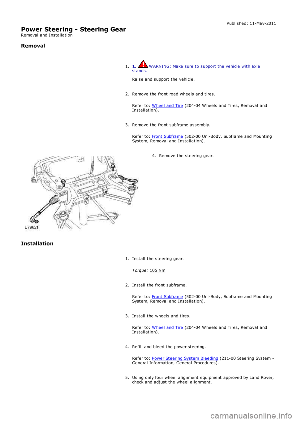
3. Remove t he s teeri ng gear.
4.
Installation Inst all t he s teeri ng gear.
T orque: 105 Nm 1.
Inst all t he front subframe.
Refer t o: Front Subframe (502-00 Uni -Body, Subframe and Mount ing
Syst em, Removal and Ins tall ati on).
2.
Inst all t he wheel s and t ires .
Refer t o: W heel and Ti re (204-04 W heel s and Tires, Removal and
Inst all at ion).
3.
Refi ll and bleed t he power st eeri ng.
Refer t o: Power St eering Sys tem Bleeding (211-00 St eering Sys tem -
General Informat ion, General Procedures ).
4.
Us ing onl y four wheel al ignment equi pment approved by Land Rover,
check and adjus t t he wheel al ignment.
5.
Page 561 of 3229
Publi s hed: 11-May-2011
Power Steering - Power Steering Fluid Cooler
Removal and Inst all ati on
Removal
1. W ARNING: Do not work on or under a vehi cle s upported onl yby a jack. Al ways support t he vehi cl e on s afet y s tands .
Rais e and s upport t he vehi cl e.
1.
Remove t he front wheel s and ti res .
Refer t o: W heel and Ti re (204-04 W heel s and Tires, Removal andInst all at ion).
2.
Remove t he front bumper.
Refer t o: Front Bumper (501-19 Bumpers , Removal and Ins tall ati on).
3.
Remove t he RH headlamp as s embly.
Refer t o: Headl amp As sembl y (417-01 Ext eri or Li ght ing, Removaland Inst all at ion).
4.
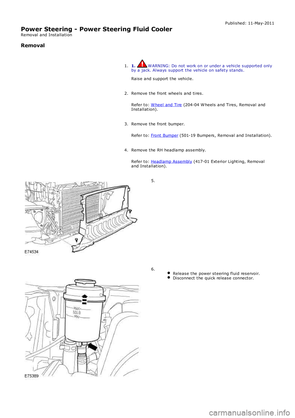
5.
Releas e t he power s t eering flui d res ervoir.Di sconnect t he qui ck rel eas e connect or.
6.
Page 565 of 3229
Publi s hed: 11-May-2011
Steering Linkage - Steering Linkage
Des cript ion and Operat ion
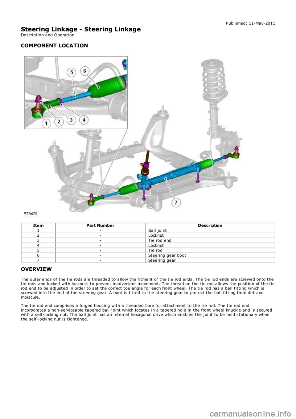
COMPONENT LOCATION
ItemPart NumberDescription
1-Ball joi nt2-Locknut
3-Tie rod end
4-Locknut5-Tie rod
6-Steeri ng gear boot
7-Steeri ng gear
OVERVIEW
The outer ends of the t ie rods are threaded t o al low t he fit ment of t he t ie rod ends. The t ie rod ends are s crewed onto t het ie rods and locked wit h locknut s t o prevent inadvertent movement. The t hread on t he t ie rod all ows the pos it ion of t he t ierod end to be adjust ed i n order t o s et the correct t oe angle for each front wheel. The t ie rod has a ball fit ti ng which i ss crewed int o t he end of the s t eering gear. A boot is fit ted t o t he s teering gear to protect t he bal l fi tt ing from dirt andmois t ure.
The t ie rod end compris es a forged hous ing wi th a t hreaded bore for at tachment to the t ie rod. The t ie rod endincorporat es a non-s ervi ceable t apered ball joint which l ocat es in a tapered hol e in the front wheel knuckl e and i s s ecuredwit h a sel f-locki ng nut. The ball joint has an int ernal hexagonal drive which enables t he joi nt to be hel d s t at ionary whent he sel f-locki ng nut is t ight ened.
Page 567 of 3229
Publi s hed: 11-May-2011
Steering Linkage - Tie Rod End
Removal and Inst all ati on
Special T ool(s) 205-754
Spli tt er, Ball Joint s
Removal 1. W ARNING: Do not work on or under a vehi cle s upported onl y
by a jack. Al ways support t he vehi cl e on s afet y s tands .
Rais e and s upport t he vehi cl e.
1.
Remove t he front wheel .
Refer t o: W heel and Ti re (204-04 W heel s and Tires, Removal and
Inst all at ion).
2.
Loosen t he t ie-rod end l ock nut .
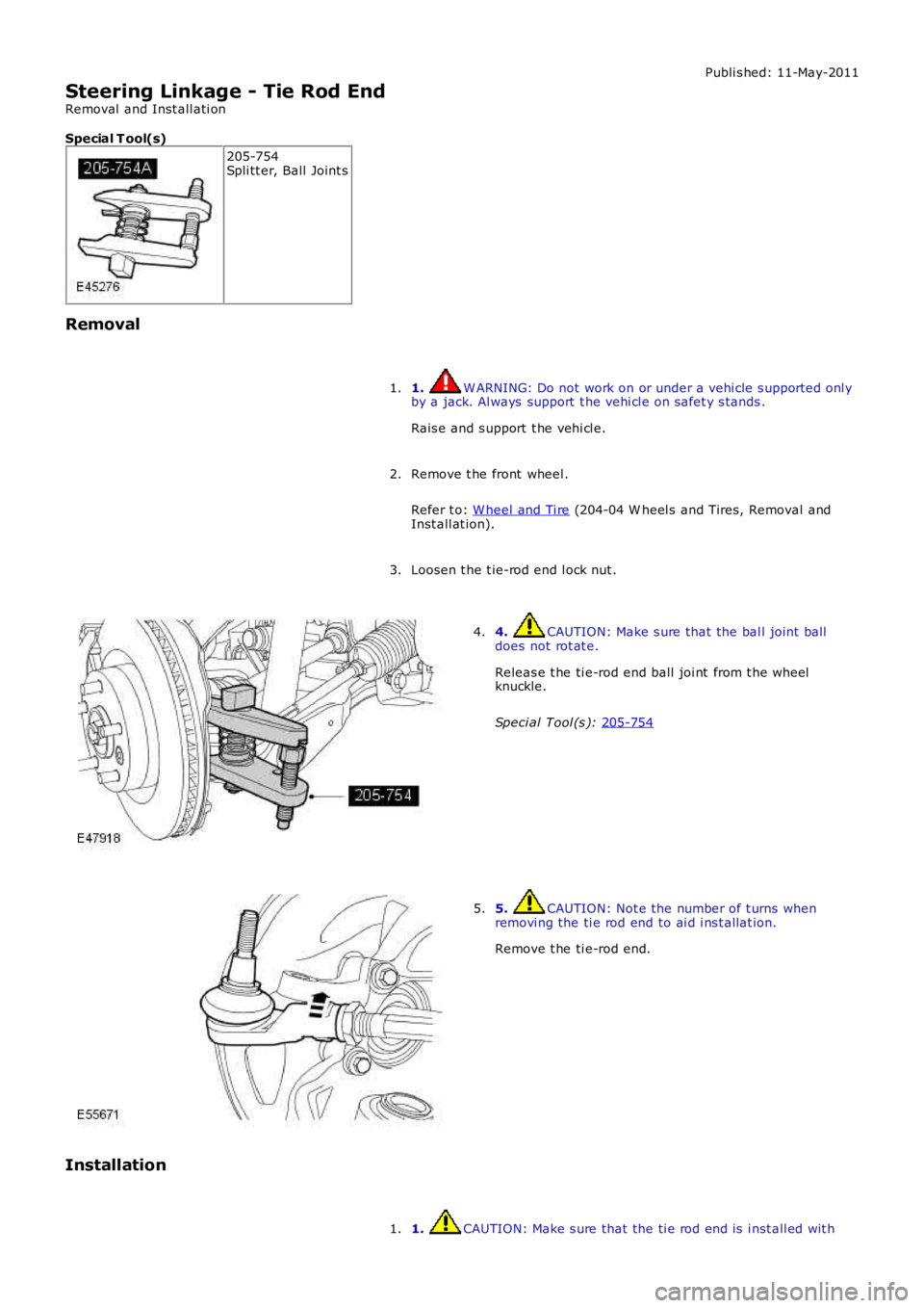
3. 4. CAUTION: Make s ure that the bal l joint ball
does not rot at e.
Releas e t he ti e-rod end ball joi nt from t he wheel
knuckle.
Speci al Tool (s ): 205-754 4.
5. CAUTION: Not e the number of t urns when
removi ng the ti e rod end to ai d i ns t allat ion.
Remove t he ti e-rod end.
5.
Installation 1. CAUTION: Make s ure that the ti e rod end is i nst all ed wit h
1.