2006 LAND ROVER FRELANDER 2 clock
[x] Cancel search: clockPage 1870 of 3229
ClockAntenna powerLight Emit t ing Di ode (LED) il lumi nat ion.
In transi t mode t he CAN port and t he ON/OFF s wit ch are t he only ci rcuit s that are left act ive.
The CAN port is l eft open to allow the EXIT from transi t mode s ignal to be received. The O N/OFF s wit ch is left act ive t oall ow feedback to the driver vi a t he head uni t LCD (liqui d crys tal dis play), t hat the unit is i n t ransi t mode s houl d t he dri veratt empt t o power up the head unit . This wi ll only occur when t he vehicle engine is runni ng and the bat tery is above 12.3Volt s.
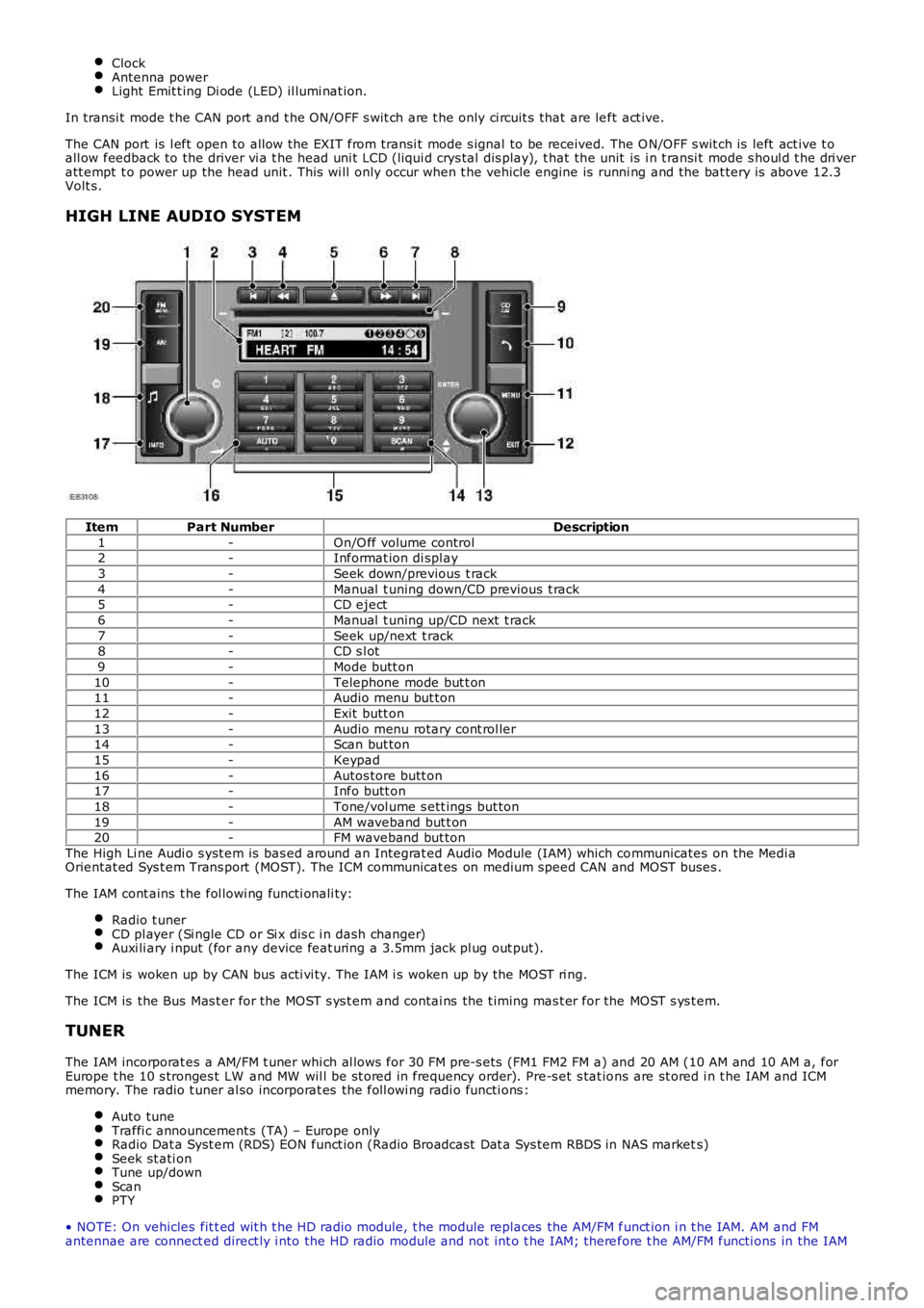
HIGH LINE AUDIO SYSTEM
ItemPart NumberDescription
1-On/O ff volume control2-Informat ion di spl ay
3-Seek down/previous t rack
4-Manual t uning down/CD previous t rack5-CD eject
6-Manual t uning up/CD next t rack
7-Seek up/next t rack8-CD s l ot
9-Mode butt on
10-Telephone mode but t on11-Audio menu but ton
12-Exit butt on
13-Audio menu rotary cont rol ler14-Scan but ton
15-Keypad
16-Autos tore butt on17-Info butt on
18-Tone/vol ume s ett ings but ton
19-AM waveband but t on20-FM waveband but ton
The High Li ne Audi o s yst em is bas ed around an Integrat ed Audio Module (IAM) which communicates on the Medi aOrientat ed Sys t em Trans port (MOST). The ICM communicat es on medium speed CAN and MOST buses .
The IAM cont ains t he fol lowi ng functi onali ty:
Radio t unerCD pl ayer (Si ngle CD or Si x dis c i n dash changer)Auxi li ary i nput (for any device feat uring a 3.5mm jack pl ug out put).
The ICM is woken up by CAN bus acti vi ty. The IAM i s woken up by the MOST ri ng.
The ICM is the Bus Mas t er for the MOST s ys t em and contai ns the t iming mas t er for the MOST s ys t em.
TUNER
The IAM incorporat es a AM/FM t uner whi ch al lows for 30 FM pre-s ets (FM1 FM2 FM a) and 20 AM (10 AM and 10 AM a, forEurope t he 10 s tronges t LW and MW wil l be st ored in frequency order). Pre-s et s tat ions are st ored i n t he IAM and ICMmemory. The radio t uner al so incorporat es the foll owi ng radi o functi ons :
Auto tuneTraffi c announcement s (TA) – Europe onlyRadio Dat a Syst em (RDS) EON funct ion (Radio Broadcast Dat a Sys tem RBDS in NAS markets)Seek st ati onTune up/downScanPTY
• NOTE: On vehicles fit t ed wit h t he HD radio module, t he module replaces the AM/FM funct ion i n t he IAM. AM and FMantennae are connect ed direct ly i nto the HD radio module and not int o t he IAM; therefore t he AM/FM functi ons in the IAM
Page 1874 of 3229
anal ogue form al ongs ide t he digi tal t ransmis s ion. The HD radi o module recei ves the analogue and digi tal s ignals vi a thevehi cl e AM and FM antennae along wi th accompanyi ng text t ransmis s ions. Thes e s ignals are decoded by t he module andplayed as an audio out put or di spl ayed as an informati on text on t he head unit LCD dis play or t he ICM LCD di spl aydepending the s ys tem ins tal led.
The HD radio modul e is locat ed in the LH s ide of t he luggage compartment . The modul e receives a fus ed power s upplyfrom the AJB. The modul e i s als o connected on the MOST ri ng and is abl e t o communicate wit h the ot her ent ert ainmentand informat ion s ys tems i n t he vehi cl e.
CLOCK
The ICM cont ains t he mas ter clock funct ional it y. Other vehi cl e i nfotai nment modul es that require clock funct ional it y us et he ti me s upplied from t he ICM.
The clock is avail abl e t o any cont rol module that is connect ed t o an i nt erconnect ing bus , for exampl e, ei ther of t he CANbuses or t he MOST ring.
The clock dis play configurabl e t o s how in AM / PM or 24 hour format . Midnight is shown as 12:00AM or 00:00 respecti vel y.The default condi ti on, if not specified, aft er power on or deli very, s hould defaul t to 12:00PM or 00:00. Depending upon t hemarket s et the cl ock will defaul t to ei ther 12 or 24 hour format.
The t ime is adjus t ed from t he ICM. Under condi ti ons when any bus could be asl eep or shut down, the ICM does not all owclock adjus tment s.
AMPLIFIERS
The audi o s yst em has three amplificati on opti ons dependant on t he audio s ys tem s pecified:
Int ernal ampli fi erHarman kardonHarman kardon LOGIC 7
The ampli fi er i s l ocated in t he Right Hand (RH) corner of t he luggage compartment and i s connected to t he audio s ys temvia t he MOST bus . Speaker connecti ons are hardwi red.
CONTROL DIAGRAM
• NOTE: A = Hardwi red connect ion; D = Medium s peed CAN bus ; P = MOST
Page 1887 of 3229
PRINCIPLES OF OPERATION
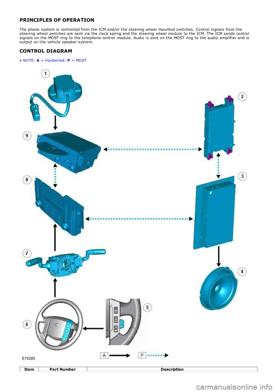
The phone sys tem is cont roll ed from the ICM and/or t he s teering wheel mount ed s wit ches . Control s i gnal s from t hes teeri ng wheel swi tches are sent via the clock s pri ng and the st eeri ng wheel module to the ICM. The ICM s ends controls ignals on t he MOST ring to the t elephone cont rol module. Audi o i s s ent on t he MOST ring to the audio ampl ifier and isoutput on t he vehi cl e s peaker s ys t em.
CONTROL DIAGRAM
• NOTE: A = Hardwi red; P = MOST
ItemPart NumberDescription
Page 1888 of 3229

1-Microphone
2-Telephone control modul e
3-Audi o ampl ifi er4-Speakers
5-Steeri ng wheel mount ed call s wit ches
6-Steeri ng wheel mount ed audio control s wi tches7-Clocks pring
8-Infotainment control modul e (ICM)
9-Int egrated audi o module (IAM)
Page 1962 of 3229
Publi s hed: 11-May-2011
Module Communications Network - Communications Network
Des cript ion and Operat ion
OVERVIEW
A number of different t ypes of communicati on network are incorporated into the vehicle wiring harnes s es for t het ransmis s ion of commands and informat ion between control modul es. The confi gurati on ins tal led on a parti cul ar vehicl edepends on t he model and equi pment level .
The communicati on net works avail abl e on t he vehi cl e are:
Local Int erconnect Network (LIN) busMedium speed Controll er Area Network (CAN) busHigh speed CAN busMedia O rient ated Sys tem Trans port (MO ST) ring
BusBaud Rate
LIN bus9.6 kbit s /s
Medium s peed CAN bus125 kbi ts /sHi gh Speed CAN bus500 kbi ts /s
MOST ring24 Mbit s/s
LOCAL INTERCONNECT NETWORK BUS
The Local Int erconnect Network (LIN) bus is a low s peed broadcas t net work that employs mas ter and s lave component s .The mas ter component t rans mit s a mess age along a si ngle wi re to the s lave component s i dent ifyi ng which s lave i s t ores pond. The mes s age has a header (s lave ident ifi er) and an empt y data fi eld. The identi fi ed s lave component fi ll s thedata fiel d wi th t he relevant i nformat ion and ret urns a mes s age to the mast er component along t he s ame wire.
CONTROLLER AREA NETWORK BUS
The Control ler Area Network (CAN) bus i s a high speed broadcast net work where cont rol modules aut omat icall y t rans mitinformat ion every few micros econds . Informati on is broadcas t down a pair of t wis t ed wires, known as 'CAN high' and 'CANlow'. Informat ion i s transmit ted on t he CAN bus as a vol tage di fference bet ween t he 2 wi res .
Two CAN bus net works are used on the vehicle; medi um s peed and high s peed, wi th the Cent ral Juncti on Box (CJB) acti ngas a gat eway bet ween t he 2 networks . The t abl e below shows t he wi re colors us ed on both net works .
Netw orkHighLow
Medium SpeedGrey and orangeViol et and orange
Hi gh SpeedW hit e and bl ueW hi te
MEDIA ORIENTATED SYSTEM TRANSPORT (MOST) RING
The Media O rient ated Sys tem Trans port (MO ST) ring us es fiber opt ic cables t o t rans port data and audio s ignal s around t heinformat ion and ent ertai nment sys tem. The fiber opti c cabl es are arranged in a ri ng, wit h each uni t on t he ri ng havi ng a'MOST in' and 'MOST out ' connect ion.
The MOST ring i s a s ynchronous net work. A t imi ng mas ter s uppl ies t he clock and all ot her component s on t he ri ngs ynchronize t heir operat ion t o t hi s clock. The t iming mas t er for the MOST ri ng is the i ntegrat ed cont rol module.
W hen handli ng MOST fiber opt ic cables t he fol lowi ng precaut ions s houl d be obs erved:
Aft er dis connect ion of any cables careful ly i nst all appropri ate dus t caps to protect the mati ng faces of theconnectors from damage and contami nat ion.Avoi d i nt roducing bends of les s t han 25 mm (0.98 inches ) radi us or ki nks int o the fiber opti c cabl e duri ng s ervice orrepair. Tight bends or kinks could i mpair operat ion, caus e immediate s ys t em failure, or future s ys t em fail ure.Avoi d exces s ive force, st rai n or s tress on the fibers or connect ors es peci ally permanent st res s after rei nst all at ion.
Ring Break Diag nostics
Incorporat ed i nt o t he Auxili ary Junct ion Box (AJB) is a Ri ng Break Di agnos ti cs (RBD) l ink. The RBD li nk hous es a copper linkwhich when removed init iat es the ri ng break diagnost ics mode. The ri ng break di agnosti cs mode allows the t echni ci an tolocate an opt ical fi ber break in t he MOST ring. To i nit iate the ring break diagnos t ics mode, carry out t he fol lowi ng proces s :
Connect t he Land Rover approved di agnos ti c s yst em.Ensure t he vehi cl e is in power mode 4 or great er.Remove the RBD li nk for t he length of ti me s peci fi ed by the Land Rover approved di agnos ti c s ys t em.Replace the RBD li nk.
Aft er approxi matel y 30 s econds a Di agnos t ic Trouble Code (DTC) wi ll be logged i n the Int egrated Cont rol Modul e,identi fyi ng the l ocat ion of t he faul t. The DTC can be read and int errogat ed usi ng t he Land Rover approved di agnos ti cs ys t em.
CONTROL DIAGRAM - LIN BUS (SHEET 1 OF 2)
• NOTE: O = LIN bus
Page 2072 of 3229
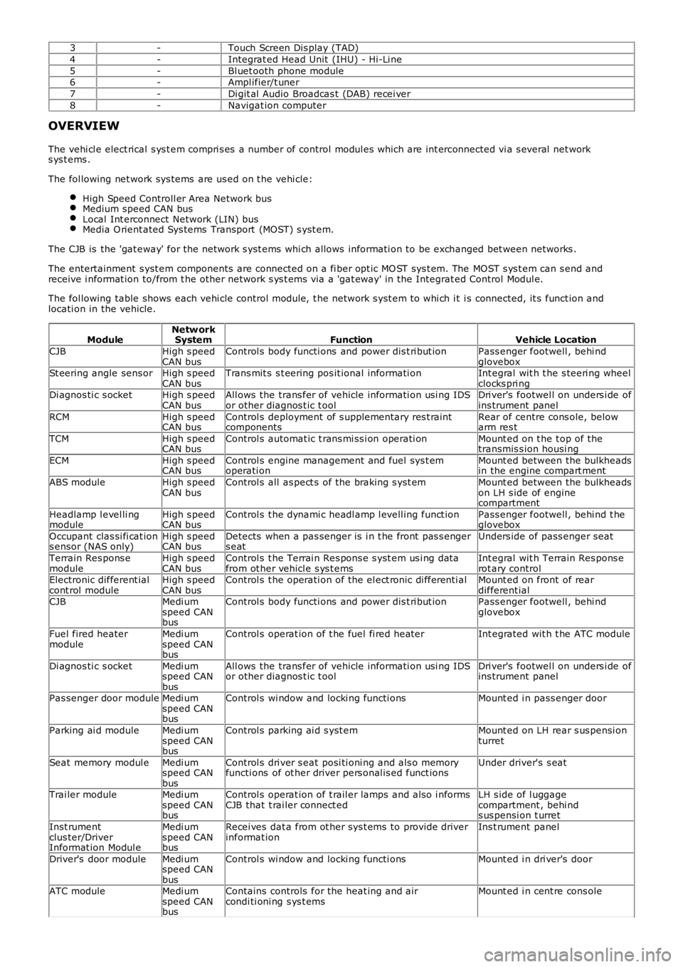
3-Touch Screen Dis play (TAD)
4-Integrat ed Head Unit (IHU) - Hi-Li ne
5-Bl uet ooth phone module6-Ampl ifier/t uner
7-Di git al Audio Broadcas t (DAB) recei ver
8-Navigat ion computer
OVERVIEW
The vehi cl e elect rical s ys t em compri s es a number of control modul es which are int erconnected vi a s everal net works ys t ems .
The fol lowing net work sys tems are us ed on t he vehi cle:
High Speed Controll er Area Network busMedium speed CAN busLocal Int erconnect Network (LIN) busMedia O rient ated Sys tems Transport (MOST) s yst em.
The CJB is the 'gat eway' for the net work s yst ems whi ch allows informati on to be exchanged bet ween networks .
The entertainment s yst em components are connected on a fi ber opt ic MO ST sys t em. The MOST s ys t em can s end andreceive i nformat ion to/from t he other network s ys t ems via a 'gat eway' in the Integrat ed Control Modul e.
The fol lowing table shows each vehi cle control modul e, t he network s yst em to whi ch it i s connected, it s funct ion andlocati on in the vehicle.
ModuleNetw orkSystemFunctionVehicle Location
CJBHigh s peedCAN busControl s body functi ons and power dis t ri but ionPass enger footwell , behi ndgloveboxSt eering angle sens orHigh s peedCAN busTrans mit s s t eering pos it ional informati onInt egral wit h t he s teeri ng wheelclocks pri ngDi agnos ti c s ocketHigh s peedCAN busAll ows the trans fer of vehicle informati on usi ng IDSor other diagnos t ic t oolDri ver's footwel l on unders i de ofins trument panel
RCMHigh s peedCAN busControl s deployment of s upplementary res t raintcomponentsRear of centre cons ole, belowarm res t
TCMHigh s peedCAN busControl s automat ic t rans mi ss i on operati onMount ed on t he t op of thetransmis s ion housi ng
ECMHigh s peedCAN busControl s engine management and fuel sys t emoperati onMount ed between the bulkheadsin the engine compart ment
ABS moduleHigh s peedCAN busControl s all as pect s of the braking s yst emMount ed between the bulkheadson LH s ide of enginecompartment
Headlamp l evel li ngmoduleHigh s peedCAN busControl s t he dynami c headl amp l evell ing funct ionPass enger footwell , behi nd t heglovebox
Occupant clas si fi cat ions ensor (NAS only)High s peedCAN busDetects when a pas senger is i n t he front pas s engers eatUnders ide of pass enger seat
Terrain Res pons emoduleHigh s peedCAN busControl s t he Terrai n Res pons e s yst em us i ng dat afrom ot her vehicl e s ys t emsInt egral wit h Terrain Res pons erot ary controlElectronic different ialcont rol moduleHigh s peedCAN busControl s t he operati on of the el ect ronic di fferenti alMount ed on front of reardifferent ialCJBMedi umspeed CANbus
Control s body functi ons and power dis t ri but ionPass enger footwell , behi ndglovebox
Fuel fired heatermoduleMedi umspeed CANbus
Control s operat ion of t he fuel fi red heaterInt egrated wit h t he ATC module
Di agnos ti c s ocketMedi umspeed CANbus
All ows the trans fer of vehicle informati on usi ng IDSor other diagnos t ic t oolDri ver's footwel l on unders i de ofins trument panel
Pas senger door moduleMedi umspeed CANbus
Control s wi ndow and locki ng functi onsMount ed i n pass enger door
Parking ai d moduleMedi umspeed CANbus
Control s parking ai d s yst emMount ed on LH rear s us pensi onturret
Seat memory modul eMedi umspeed CANbus
Control s dri ver s eat posi ti oni ng and als o memoryfuncti ons of ot her driver pers onal is ed funct ionsUnder driver's s eat
Trai ler moduleMedi umspeed CANbus
Control s operat ion of t rail er lamps and als o i nformsCJB that t rai ler connect edLH s ide of l uggagecompartment , behi nds us pensi on t urret
Inst rumentclus ter/DriverInformat ion Modul e
Medi umspeed CANbus
Recei ves dat a from ot her sys t ems to provide driverinformat ionIns t rument panel
Driver's door moduleMedi umspeed CANbus
Control s wi ndow and locki ng functi onsMount ed i n dri ver's door
ATC moduleMedi umspeed CANbus
Contains controls for the heat ing and aircondi ti oni ng s ys t emsMount ed i n cent re cons ole
Page 2073 of 3229
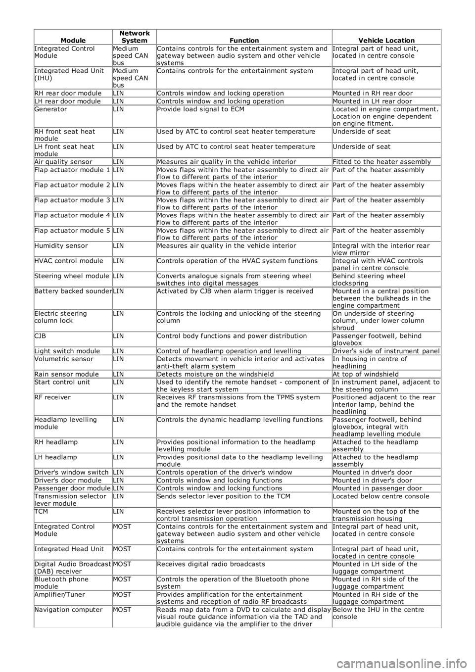
ModuleNetw orkSystemFunctionVehicle Location
Integrat ed Cont rolModuleMedi umspeed CANbus
Contains controls for the ent ert ai nment sys t em andgateway between audio s ys t em and ot her vehicles ys t ems
Int egral part of head uni t,located i n cent re cons ole
Integrat ed Head Unit(IHU)Medi umspeed CANbus
Contains controls for the ent ert ai nment sys t emInt egral part of head uni t,located i n cent re cons ole
RH rear door moduleLINControl s wi ndow and locki ng operati onMount ed i n RH rear door
LH rear door moduleLINControl s wi ndow and locki ng operati onMount ed i n LH rear doorGenerat orLINProvide l oad s ignal t o ECMLocat ed in engine compart ment .Locat ion on engine dependenton engine fit ment.
RH front s eat heatmoduleLINUs ed by ATC t o cont rol s eat heat er temperat ureUnders ide of s eat
LH front s eat heatmoduleLINUs ed by ATC t o cont rol s eat heat er temperat ureUnders ide of s eat
Air quali ty sens orLINMeasures air qualit y i n t he vehi cl e int eri orFit ted t o t he heater as sembl y
Flap act uat or modul e 1LINMoves fl aps wit hi n t he heat er ass embl y to direct airfl ow t o different parts of t he i nt eri orPart of t he heat er as s embly
Flap act uat or modul e 2LINMoves fl aps wit hi n t he heat er ass embl y to direct airfl ow t o different parts of t he i nt eri orPart of t he heat er as s embly
Flap act uat or modul e 3LINMoves fl aps wit hi n t he heat er ass embl y to direct airfl ow t o different parts of t he i nt eri orPart of t he heat er as s embly
Flap act uat or modul e 4LINMoves fl aps wit hi n t he heat er ass embl y to direct airfl ow t o different parts of t he i nt eri orPart of t he heat er as s embly
Flap act uat or modul e 5LINMoves fl aps wit hi n t he heat er ass embl y to direct airfl ow t o different parts of t he i nt eri orPart of t he heat er as s embly
Humi di ty sens orLINMeasures air qualit y i n t he vehi cl e int eri orInt egral wit h t he int eri or rearview mirror
HVAC control modul eLINControl s operat ion of t he HVAC s ys t em funct ionsInt egral wit h HVAC controlspanel i n cent re cons ole
St eering wheel moduleLINConverts analogue s ignals from s teering wheels wit ches i nto di git al mes s agesBehi nd s teering wheelclocks pri ngBatt ery backed s ounderLINActi vat ed by CJB when alarm t ri gger i s receivedMount ed i n a central pos it ionbetween t he bulkheads i n t heengi ne compartment
Electric st eeringcolumn l ockLINControl s t he locking and unlocki ng of the st eeri ngcol umnOn unders ide of s t eeringcol umn, under lower columns hroud
CJBLINControl body funct ions and power di st ributi onPass enger footwell , behi ndglovebox
Light s wit ch moduleLINControl of headlamp operat ion and l evel lingDri ver's s i de of ins trument panelVolumet ri c s ens orLINDetects movement i n vehicle i nterior and act ivatesanti -t heft alarm s ys temIn hous ing in centre ofheadl ining
Rain sens or modul eLINDetects mois t ure on t he wi nds hiel dAt top of windshi el dSt art cont rol unitLINUs ed to identi fy t he remote hands et - component oft he keyles s s t art s yst emIn ins trument panel, adjacent tothe st eeri ng col umnRF recei verLINRecei ves RF trans mi s si ons from t he TPMS s yst emand t he remot e hands etPosi ti oned adjacent t o the rearint erior l amp, behi nd theheadl ining
Headlamp l evel li ngmoduleLINControl s t he dynami c headl amp l evell ing funct ionsPass enger footwell , behi ndglovebox, int egral wit hheadl amp levell ing module
RH headlampLINProvides pos it ional i nformati on to the headlamplevell ing moduleAtt ached t o t he headl ampass embl y
LH headlampLINProvides pos it ional dat a t o t he headlamp levell ingmoduleAtt ached t o t he headl ampass embl y
Driver's window s wi tchLINControl s operat ion of t he driver's wi ndowMount ed i n dri ver's door
Driver's door moduleLINControl s wi ndow and locki ng functi onsMount ed i n dri ver's doorPas senger door moduleLINControl s wi ndow and locki ng functi onsMount ed i n pass enger door
Trans mi ss ion sel ect orl ever moduleLINSends sel ect or l ever pos it ion t o t he TCMLocat ed bel ow centre cons ole
TCMLINRecei ves s elect or l ever pos it ion i nformat ion tocont rol t rans mis s ion operat ionMount ed on t he t op of thetransmis s ion housi ngIntegrat ed Cont rolModuleMOSTContains controls for the ent ert ai nment sys t em andgateway between audio s ys t em and ot her vehicles ys t ems
Int egral part of head uni t,located i n cent re cons ole
Integrat ed Head UnitMOSTContains controls for the ent ert ai nment sys t emInt egral part of head uni t,located i n cent re cons oleDi gi tal Audio Broadcas t(DAB) recei verMOSTRecei ves di git al radi o broadcast sMount ed i n LH s ide of t heluggage compartmentBluet oot h phonemoduleMOSTControl s t he operati on of the Bl uet ooth phones ys t emMount ed i n RH s i de of theluggage compartment
Ampl ifi er/TunerMOSTProvides ampl ifi cat ion for the ent ert ainments ys t ems and recepti on of radio RF broadcas t sMount ed i n RH s i de of theluggage compartment
Navigati on comput erMOSTReads map data from a DVD t o cal cul ate and di spl ayvis ual route gui dance i nformat ion vi a t he TAD andaudi ble gui dance via the ampl ifier to the driver
Below t he IHU i n t he cent recons ole
Page 2280 of 3229
Publi s hed: 11-May-2011
Instrument Panel and Console - Instrument Panel Upper Section
Removal and Inst all ati on
Removal
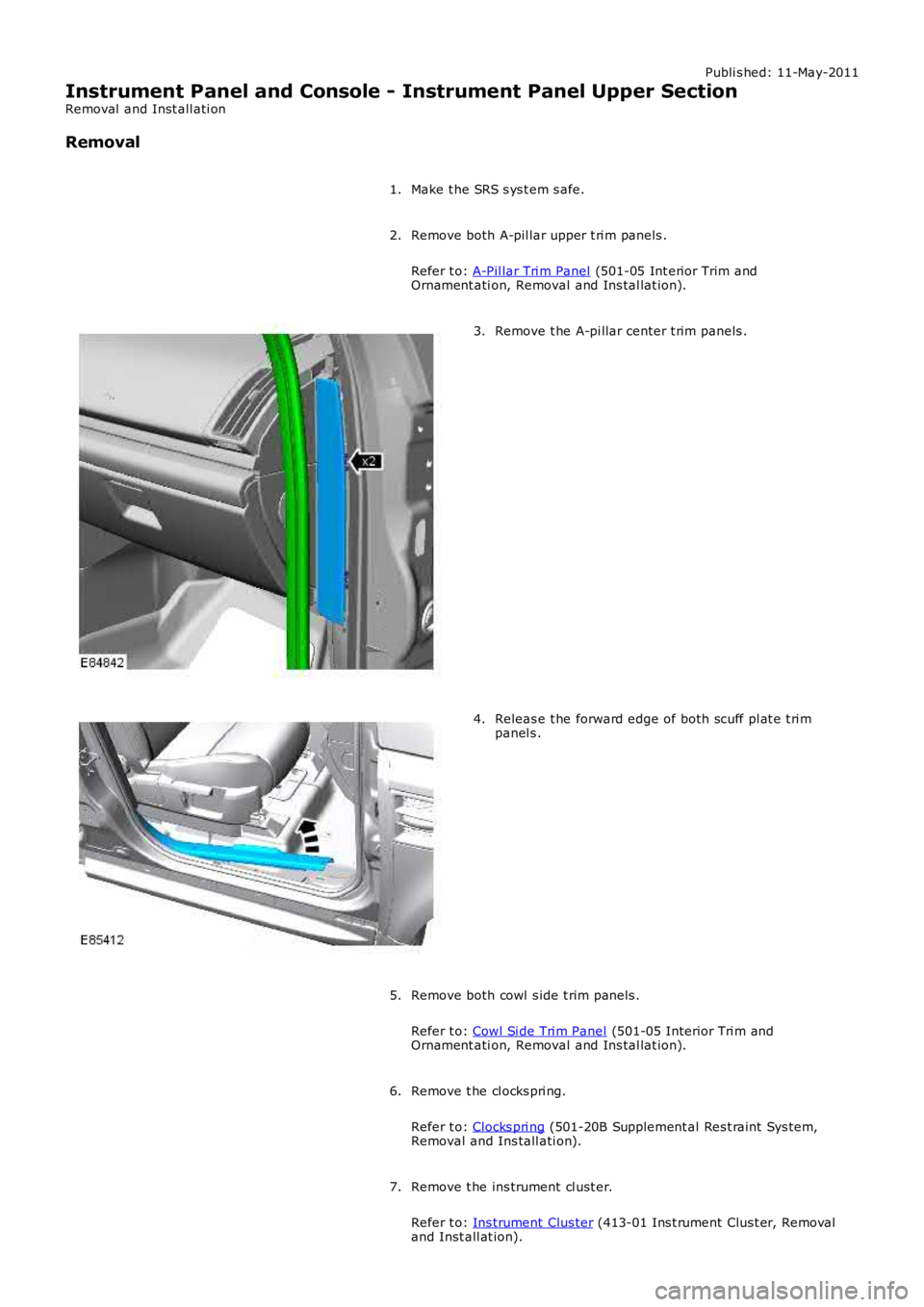
Make t he SRS s ys t em s afe.1.
Remove both A-pil lar upper t ri m panels .
Refer t o: A-Pil lar Tri m Panel (501-05 Int erior Trim andOrnament ati on, Removal and Ins tal lat ion).
2.
Remove t he A-pi llar center t rim panels .3.
Releas e t he forward edge of both scuff pl at e t ri mpanel s .4.
Remove both cowl s ide t rim panels .
Refer t o: Cowl Si de Tri m Panel (501-05 Interior Tri m andOrnament ati on, Removal and Ins tal lat ion).
5.
Remove t he cl ocks pri ng.
Refer t o: Clocks pri ng (501-20B Supplement al Res t raint Sys tem,Removal and Ins tall ati on).
6.
Remove t he ins trument cl ust er.
Refer t o: Ins trument Clus ter (413-01 Ins t rument Clus t er, Removaland Inst all at ion).
7.