2006 LAND ROVER FRELANDER 2 oil temperature
[x] Cancel search: oil temperaturePage 1134 of 3229
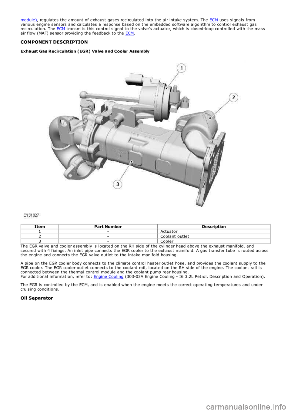
module), regulates t he amount of exhaus t gas es reci rculated into the ai r int ake s ys tem. The ECM uses s i gnals fromvarious engine s ens ors and calculates a res pons e bas ed on t he embedded software algori thm t o cont rol exhaus t gasrecircul ati on. The ECM trans mi ts this cont rol s ignal t o t he valve's actuat or, which i s clos ed-loop controlled wit h t he mas sair flow (MAF) s ens or providi ng the feedback t o t he ECM.
COMPONENT DESCRIPTION
Exhaust Gas R ecirculation (EGR) Valve and Cooler Assembly
ItemPart NumberDescription1-Actuator
2-Coolant out let
3-CoolerThe EGR valve and cooler ass embl y is l ocat ed on t he RH s ide of t he cylinder head above t he exhaus t manifold, ands ecured wit h 4 fixi ngs . An i nl et pipe connects the EGR cooler t o t he exhaus t manifold. A gas t rans fer t ube is rout ed acros st he engi ne and connect s t he EGR valve out let t o the intake mani fold hous ing.
A pi pe on t he EGR cool er body connect s to the cl imat e cont rol heater outl et hos e, and provides t he cool ant s upply t o t heEGR cooler. The EGR cooler outl et connect s t o t he cool ant rail , locat ed on t he RH s ide of the engine. The cool ant rail isconnected bet ween the t hermal control modul e and the coolant pump rear hous ing.For addit ional informat ion, refer t o: Engi ne Cooling (303-03A Engine Cooli ng - I6 3.2L Pet rol, Des cri pt ion and Operati on).
The EGR i s cont rol led by t he ECM, and is enabled when t he engine meet s t he correct operati ng temperatures and undercruis i ng condit ions .
Oil Separator
Page 1206 of 3229
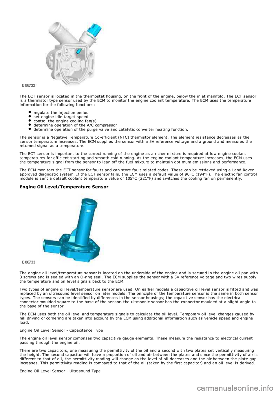
The ECT s ens or is locat ed i n t he thermost at hous ing, on t he front of the engine, below t he i nl et manifol d. The ECT s ens oris a t hermis t or type s ens or us ed by the ECM t o monit or the engine coolant t emperature. The ECM uses t he t emperatureinformat ion for the foll owi ng functi ons:
regulat e t he inject ion peri ods et engi ne idle target s peedcont rol t he engi ne cool ing fan(s )determine operat ion of t he A/C compres sordetermine operat ion of t he purge valve and catal yt ic convert er heat ing funct ion.
The s ens or is a Negat ive Temperat ure Co-efficient (NTC) thermis tor element . The element res is t ance decreas es as thes ens or t emperature increas es. The ECM suppli es the sens or wit h a 5V reference volt age and a ground and meas ures theret urned s ignal as a t emperature.
The ECT s ens or is important to the correct running of t he engi ne as a richer mixt ure i s required at low engi ne cool antt emperatures for efficient s tarti ng and s mooth cold running. As t he engi ne cool ant temperat ure i ncreas es , the ECM usest he temperat ure si gnal from the sens or to l ean off t he fuel mi xt ure to maint ai n optimum emis s ions and performance.
The ECM moni tors the ECT sens or for faul ts and can s t ore faul t rel at ed codes . These can be ret ri eved us ing a Land Roverapproved diagnos t ic s yst em. If the ECT sens or fail s, t he ECM us es a defaul t val ue of 90°C (194°F). The electric fan cont rolmodule i s s ent a default coolant temperat ure val ue of 105°C (221°F) and s wit ches t he cooling fan on permanent ly.
Engine Oil Level/Temperature Sensor
The engi ne oil l evel/t emperature s ens or is locat ed on t he unders ide of t he engi ne and is secured i n t he engi ne oil pan wi th3 s crews and i s s eal ed wi th an O-ring s eal. The ECM suppli es the s ens or wit h a 5V reference volt age and two wires s uppl yt he temperat ure and oi l level si gnal s back t o t he ECM.
Two t ypes of engine oi l level /t emperat ure s ensor are us ed. On earli er model s a capacit ive oi l level s ens or i s fit ted and wasrepl aced by an ul trasound l evel s ens or on l at er models . The principl e of the temperat ure s ens or i s t he s ame in bot h s ens ort ypes . The sens ors can be i dent ified by di fferences in t he s ens or housi ngs ; t he capacit ive s ensor has t he electricalconnector moulded s quare t o t he bas e of the s ens or, t he ult ras oni c s ens or has the connect or moulded at a s li ght angle tot he bas e of t he s ens or.
The ECM us es both the oi l l evel and t emperature s ignals t o calculat e t he oil level. Temporary oil level changes caus ed byhil l driving or cornering are taken i nt o account by t he ECM us ing addit ional informat ion s uch as vehi cl e s peed and engi neload.
Engi ne Oi l Level Sens or - Capacit ance Type
The engi ne oil l evel s ens or compris es t wo capaci ti ve gauge el ement s . Thes e meas ure the resi s tance to elect rical currentpass i ng through t he engine oi l.
There are t wo capacit ors , one meas uring t he permit ti vi ty of t he oil and a second with t wo pl at es s et verti cal ly meas uri ngt he hei ght . The s econd capaci tor wil l have a proport ion of oil and ai r bet ween t he plates and s i nce t he permit ti vi ty of ai r isdifferent t o t hat of oi l, t he permi tt ivit y readi ng wil l change as t he level of oi l decreas es and the ai r between t he plat e gapincreas es. This permi tt ivit y readi ng is compared t o t hat of the oi l (t aken by t he first capaci tor) and an oil level is derived.
Engi ne Oi l Level Sens or - Ult ras ound Type
Page 1207 of 3229
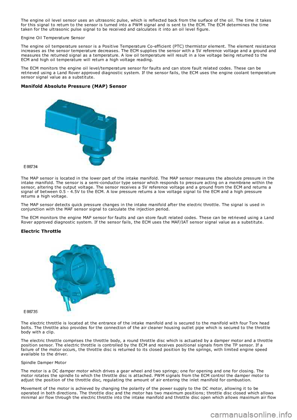
The engi ne oil l evel s ens or us es an ult ras oni c puls e, which is refl ect ed back from the s urface of t he oil . The ti me i t takesfor t his s i gnal t o ret urn t o t he s ensor i s turned int o a PW M s ignal and is s ent to the ECM. The ECM det ermi nes the ti met aken for the ul trasonic pul se si gnal t o be recei ved and calculat es it i nto an oil level fi gure.
Engi ne Oi l Temperat ure Sens or
The engi ne oil t emperature s ensor i s a Pos it ive Temperat ure Co-effi ci ent (PTC) thermis t or el ement . The element res i st anceincreas es as t he sens or temperat ure decreas es. The ECM s uppli es t he sens or wit h a 5V reference vol tage and a ground andmeas ures t he ret urned s ignal as a t emperature. A low oil temperature wil l res ult in a l ow volt age bei ng ret urned t o t heECM and hi gh oil temperature wil l ret urn a hi gh volt age reading.
The ECM moni tors the engine oi l level/temperat ure sens or for fault s and can s tore faul t rel at ed codes . These can beret ri eved us i ng a Land Rover approved diagnos t ic s ys tem. If the sens or fail s , the ECM us es t he engine cool ant temperat ures ens or s ignal val ue as a s ubst it ute.
Manifold Absolute Pressure (MAP) Sensor
The MAP s ensor i s located i n t he lower part of t he int ake manifol d. The MAP s ens or meas ures t he abs olut e pres s ure in t heint ake manifol d. The sens or is a semi -conduct or type s ens or which responds t o pres s ure acti ng on a membrane wi thin thes ens or, al tering t he output volt age. The s ens or receives a 5V reference vol tage and a ground from t he ECM and returns as ignal of bet ween 0.5 - 4.5V t o t he ECM. A low pres sure ret urns a low vol tage s ignal to the ECM and a high press ureret urns a hi gh volt age.
The MAP s ensor det ect s quick pres s ure changes i n t he int ake mani fol d aft er the el ectri c thrott le. The s ignal is us ed inconjunct ion wi th the MAF sens or si gnal t o calculate the injecti on peri od.
The ECM moni tors the engine MAP s ens or for faul ts and can st ore fault related codes. Thes e can be ret ri eved us i ng a LandRover approved diagnost ic sys tem. If t he s ens or fai ls , the ECM uses t he MAF/IAT s ensor s i gnal value as a subs ti tut e.
Electric Throttle
The electric t hrot tl e is locat ed at t he entrance of t he int ake manifol d and is secured t o t he manifold wit h four Torx headbolt s. The t hrot tl e als o provi des for t he connect ion of t he air cleaner hous ing out let pipe which is secured t o t he t hrott lebody wit h a cl ip.
The electric t hrot tl e compri ses t he t hrott le body, a round throt t le di sc whi ch is act uat ed by a damper mot or and a thrott leposi ti on s ens or. The el ect ri c thrott le is control led by the ECM and recei ves pos i ti onal s ignals from the TP s ens or. If afai lure of the mot or occurs , t he thrott le di s c is returned to it s cl osed pos it ion by the s prings, wi th li mit ed engine s peedavai lable to the driver.
Spindle Damper Mot or
The mot or i s a DC damper motor which drives a gear wheel and t wo s pri ngs ; one for opening and one for cl osi ng. Themot or rotat es the spi ndl e t o which t he t hrott le dis c is at t ached. PW M s i gnals from the ECM control the damper mot or t oadjus t the pos it ion of t he t hrott le dis c, regul ati ng the amount of air ent ering the i nlet manifold for combus ti on.
Movement of t he mot or is achieved by changing t he polarit y of the power s uppl y to the DC mot or, all owing i t to beoperated in bot h direct ions . The throt tl e dis c and t he mot or has two maxi mum pos it ions ; t hrott le di s c cl osed which all owsmi ni mal air flow t hrough t he electric t hrot tl e int o t he int ake manifol d and t hrott le dis c open which all ows maximum air flow
Page 1209 of 3229
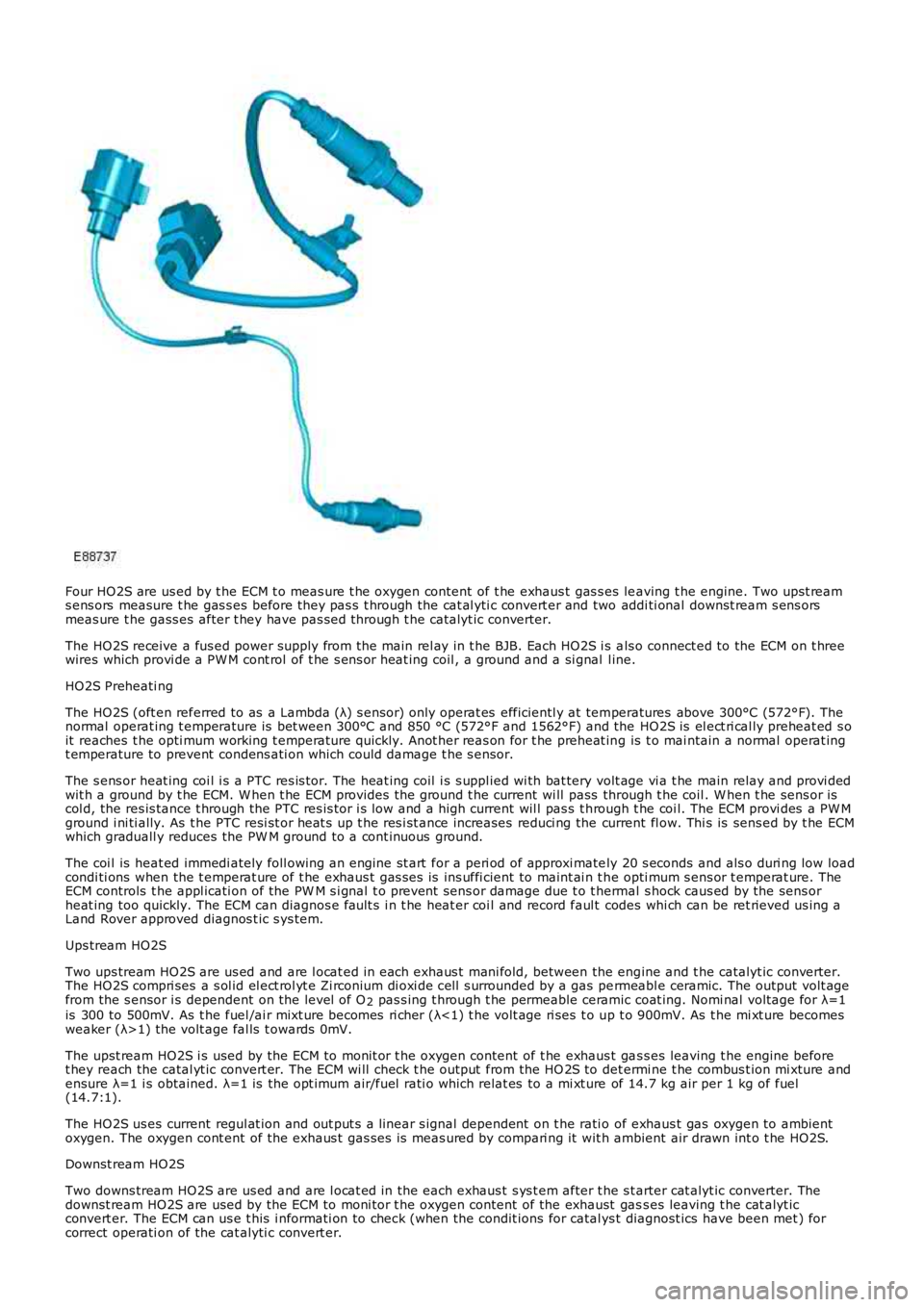
Four HO2S are us ed by t he ECM t o meas ure t he oxygen content of t he exhaus t gas s es leaving t he engine. Two upst reams ens ors measure t he gas s es before they pas s t hrough the cat al yti c convert er and two addi ti onal downst ream s ens orsmeas ure t he gass es after t hey have pas sed through t he catalyt ic converter.
The HO2S receive a fus ed power supply from t he main rel ay in t he BJB. Each HO2S i s als o connect ed to the ECM on t hreewires which provi de a PW M cont rol of t he s ens or heat ing coil , a ground and a si gnal l ine.
HO2S Preheati ng
The HO2S (oft en referred to as a Lambda (λ) s ensor) only operat es efficientl y at temperatures above 300°C (572°F). Thenormal operat ing t emperature is bet ween 300°C and 850 °C (572°F and 1562°F) and the HO2S is el ect ri cal ly preheat ed s oit reaches t he opti mum working t emperature quickly. Anot her reas on for t he preheat ing is t o mai ntain a normal operat ingt emperature to prevent condens ati on which could damage t he s ensor.
The s ens or heat ing coi l i s a PTC res is tor. The heat ing coil i s s uppl ied wi th bat tery volt age vi a t he main relay and provi dedwit h a ground by t he ECM. W hen t he ECM provides t he ground t he current wi ll pass through t he coil . W hen t he sens or iscol d, the res is tance t hrough the PTC res is tor i s low and a high current wil l pas s t hrough t he coi l. The ECM provi des a PW Mground i ni ti ally. As t he PTC resi st or heat s up t he res i st ance increases reduci ng the current fl ow. Thi s is sens ed by t he ECMwhich graduall y reduces the PW M ground to a cont inuous ground.
The coi l is heat ed immedi ately foll owing an engine st art for a peri od of approxi mately 20 s econds and als o duri ng low loadcondi ti ons when the t emperat ure of t he exhaus t gas s es is ins uffi cient to maint ai n t he opti mum s ens or t emperat ure. TheECM controls t he appl icati on of the PW M s i gnal t o prevent sens or damage due t o t hermal s hock caus ed by the sens orheat ing too quickly. The ECM can diagnos e fault s i n t he heat er coi l and record faul t codes whi ch can be ret rieved us ing aLand Rover approved diagnos t ic s ys tem.
Ups tream HO2S
Two ups tream HO2S are us ed and are l ocat ed in each exhaus t mani fold, between the engine and t he catalyt ic converter.The HO2S compri ses a s ol id el ect rol yt e Zi rconium di oxi de cel l s urrounded by a gas permeabl e ceramic. The output volt agefrom the s ensor i s dependent on the level of O2 pas s ing t hrough t he permeable ceramic coat ing. Nomi nal volt age for λ=1is 300 to 500mV. As t he fuel /ai r mixt ure becomes ri cher (λ<1) t he volt age ri ses t o up t o 900mV. As t he mi xt ure becomesweaker (λ>1) the volt age fal ls t owards 0mV.
The upst ream HO2S i s used by the ECM to monit or t he oxygen content of t he exhaus t gas s es leaving t he engine beforet hey reach the catal yt ic convert er. The ECM wi ll check t he output from the HO 2S to det ermi ne t he combus t ion mi xture andensure λ=1 i s obtained. λ=1 is the opt imum air/fuel rati o which relat es to a mi xt ure of 14.7 kg air per 1 kg of fuel(14.7:1).
The HO2S us es current regul at ion and out put s a linear s ignal dependent on t he rati o of exhaus t gas oxygen to ambientoxygen. The oxygen cont ent of the exhaus t gas ses is meas ured by compari ng it wit h ambient air drawn int o t he HO2S.
Downst ream HO2S
Two downs tream HO2S are us ed and are l ocat ed in the each exhaus t s ys t em after t he s tarter cat alyt ic converter. Thedownst ream HO2S are used by the ECM to moni tor t he oxygen content of the exhaust gass es leaving t he cat alyt icconvert er. The ECM can us e t his i nformati on to check (when the condit ions for catal ys t diagnost ics have been met ) forcorrect operati on of the cat alyti c convert er.
Page 1218 of 3229
The posi ti on of the inlet cams haft is det ermi ned by the ECM us ing s ignals from t he CKP s ens or and t he CMP s ens ors. TheECM can t hen use the VCT sol enoid val ve to cont rol t he angl e of the cams haft by controlli ng t he fl ow of oil t o t he VCT unit .
The camshaft is s ecured t o t he rot or in t he VCT unit . Oil pres s ure suppli ed to eit her s ide of t he VCT unit from t he VCTs olenoi d valve can rot ate the rotor and hence the cams haft i n eit her di recti on. The VCT sol enoi d is operat ed by t he ECMus ing PW M, hi gh frequency s wit chi ng which provi des rapid and preci se cont rol of the i nlet cams haft pos i ti on. The i nletcamshaft pos i ti on can be adjust ed wi thi n 40 degrees of cranks haft rotat ion.
Camshaft Profile Switching (CPS) Control
The inl et cams haft has , in addit ion to t he VCT control, a CPS funct ion whi ch is al so cont roll ed by t he ECM. The CPS cont rolcan vary t he val ve li ft height and durat ion of t he camshaft lobes by adjus ti ng the area of t he hydraul ic t appet whi ch act son one of t wo cam l obe profi les . The CPS cont rol is vi a t wo CPS s olenoid valves , located at each end of the i nlet cams haft.The CPS s olenoid valves cont rol t he posi ti on of hydraul ic t appet as s embli es which can be s et in one of t wo pos it ions; lowand high.
Two CPS s olenoids are us ed so that t he hydraul ic t appet s can be adjus t ed when no load i s applied, for example the camlobes are off t he hydraul ic t appet s and t he cam bas e circl e is act ing on t he t appet , thi s keeps t he s tress on components toa minimum. One CPS s ol enoi d s uppl ies oi l press ure to the hydrauli c t appet s of cyli nders 1, 2 and 4 and the s econd CPSs olenoi d s uppl ies oi l press ure to the tappet s of cylinders 3, 5 and 6.
At engi ne s tart and at low engine oi l temperat ures (below 40°C (104°F)) the ECM does not direct engine oi l pres sure t ot he hydraul ic t appet s and t herefore the hydraul ic t appet s are in t heir s pring loaded, l ow posi ti on.For addit ional informat ion, refer t o: Engi ne - 3.2L (303-01, Descripti on and Operat ion).
Ignition Control
The ECM calculat es the opt imum ignit ion ti ming bas ed on pre-programmed maps and informat ion from t he foll owings ens ors :
CKP s ensorCMP s ensorsMAF s ensorECT s ens orElectric t hrot tl e TP s ensorKnock s ens orsTCMIgni ti on coi ls .
Duri ng engi ne s tarti ng the ECM uses a fi xed ignit ion s et ti ng. W hen the engine has s tart ed and the vehicle is bei ng driven,t he ECM adjus ts the i gni ti on t imi ng accordi ngl y us ing ot her paramet ers s uch as engine s peed, l oad and temperat ure.
Once the engi ne has reached i ts normal operati ng temperature, t he ECM moni tors the si gnal s from the knock sens ors . Ifany of the cyli nders produce knocking, the i gnit ion t imi ng for t hat cyli nder wi ll be retarded unt il t he knocking has s t opped.The ignit ion is t hen gradually advanced back t o t he normal t imi ng or unt il t he knocking re-occurs .
The ECM us es informat ion from the TCM t o provide t orque l imi tat ion during t rans mis s ion s hifts . The i gni ti on ti mi ng isadjus ted t o moment ari ly reduce t he engine t orque output t o give a smoot h t rans mis s ion shi ft and reduce l oad on thet ransmis s ion.
Air Conditioning (A/C) Compressor Control
The ECM controls t he operati on of the A/C compres s or and reacts t o reques ts from t he ATC module vi a t he high s peed CANbus. The compres s or is a variable di s pl acement unit and t he ECM controls , via a sol enoi d, t he dis placement of thecompres sor t o adjus t load during cert ain driving condit ions.
Duri ng engi ne s tart-up, movi ng from a s tandst il l and under hard accelerat ion, the ECM s et s t he mi nimum dis placement oft he compress or t o reduce the effect on t he engi ne t orque output. The ECM uses i nformati on from t he ATC module, t he A/Cpres s ure s ensor, the el ect ri c t hrott le TP s ens or and the ECT sens or to det ermi ne compres sor control . The ATC modulet ransmit s climate control and driver reques ts t o t he ECM and t he ECM det ermi nes the priori ty of thes e request s overengi ne performance.
Page 1243 of 3229

12-Start cont rol s wit ch
13-Ambient air t emperat ure s ensor
14-Fuel t emperature s ensor15-IAT sens or
16-MAF s ensor
17-HO2S18-Different ial pres s ure s ens or
19-Upst ream exhaus t temperature s ens or
20-CMP s ensor21-Speed control inhibit swi tch
22-ECM
23-Oil l evel and t emperature s ens or24-EOP s ensor
CONTROL DIAGRAM SHEET 2 OF 2
• NOTE: A = Hardwi red; D = Hi gh s peed controller area net work (CAN)
Page 1271 of 3229
Publi s hed: 11-May-2011
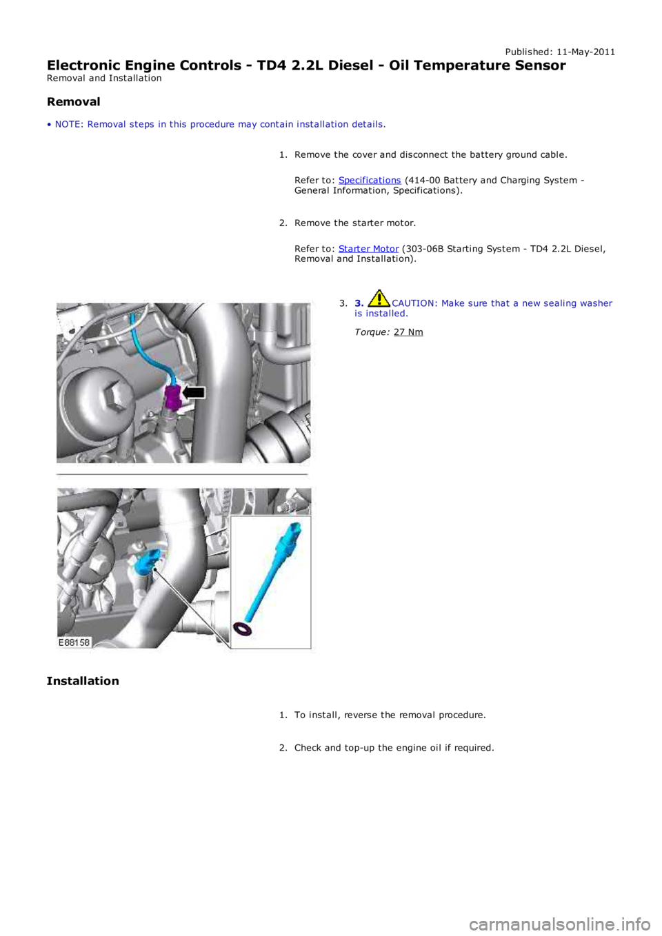
Electronic Engine Controls - TD4 2.2L Diesel - Oil Temperature Sensor
Removal and Inst all ati on
Removal
• NOTE: Removal s t eps in t his procedure may cont ain i nst all ati on det ail s.
Remove t he cover and dis connect the bat tery ground cabl e.
Refer t o: Specificati ons (414-00 Bat tery and Charging Sys tem -
General Informat ion, Specificati ons).
1.
Remove t he s tart er mot or.
Refer t o: Start er Motor (303-06B Starti ng Sys t em - TD4 2.2L Dies el,
Removal and Ins tall ati on).
2. 3. CAUTION: Make s ure that a new s eali ng was her
i s ins tal led.
T orque: 27 Nm 3.
Installation To i nst all , revers e t he removal procedure.
1.
Check and top-up the engine oi l if required.
2.
Page 2879 of 3229
159
Maintenance
R
In addition, engine se ttings must not be
tampered with. These have been established to
ensure that your vehicle complies with
stringent exhaust em ission regulations.
Incorrect engine settings may adversely affect
exhaust emissions, engi ne performance and
fuel consumption. The y may also cause high
temperatures, which will result in damage to
the catalytic converter and the vehicle.
Road testing dynamometers (rolling
roads)
Because your vehicle is equipped with anti-lock
brakes and four wheel drive, it is essential that
any dynamometer testing is carried out only by
a qualified person, familiar with the
dynamometer testing an d safety procedures
practised by Land Rove r Dealers/Authorised
Repairers.
Safety in the garage
Fuel system
Poisonous fluids
Fluids used in motor vehicles are poisonous
and should not be consumed or brought into
contact with open wounds. These include;
battery acid, antifreeze, brake, clutch and
power steering fluid, petr ol, diesel, engine oil
and windscreen washer additives.
For your own safety, al ways read and obey all
instructions printed on labels and containers.
Used engine oil
Prolonged contact with engine oil may cause
serious skin disorders, including dermatitis
and cancer of the skin. Always wash
thoroughly after contact.
It is illegal to pollute drains, water
courses or soil. Use authorised
waste disposal sites to dispose of
used oil and toxic chemicals.
WARNINGS
If the vehicle has been driven recently,
do not touch exhaust and cooling
system components un til the engine has
cooled.
Never leave the engine running in an
unventilated area - exhaust gases are
poisonous and extremely dangerous.
Do not work beneath the vehicle with
the wheel changing jack as the only
means of support.
Keep your hands and clothing away
from drive belt s and pulleys.
Remove metal wr ist bands and
jewellery, before working in the engine
compartment.
Do not touch electrical leads or
components while the engine is
running, or with the starter switch turned on.
Do not allow tools or metal parts of the
vehicle to make contact with the battery
leads or terminals.
WARNINGS
Under no circumstances should any
part of the fuel system be dismantled or
replaced by anyone other than a suitably
qualified vehicle technician. Failure to comply
with this instruction, may result in fuel spillage
with a consequent serious risk of fire.
Ensure sparks and naked lights are kept
away from the engine compartment.
Wear protective cl othing, including,
where practicable, gloves made from
an impervious material.
WARNINGS