2006 LAND ROVER FRELANDER 2 alarm
[x] Cancel search: alarmPage 2056 of 3229
Publi s hed: 11-May-2011
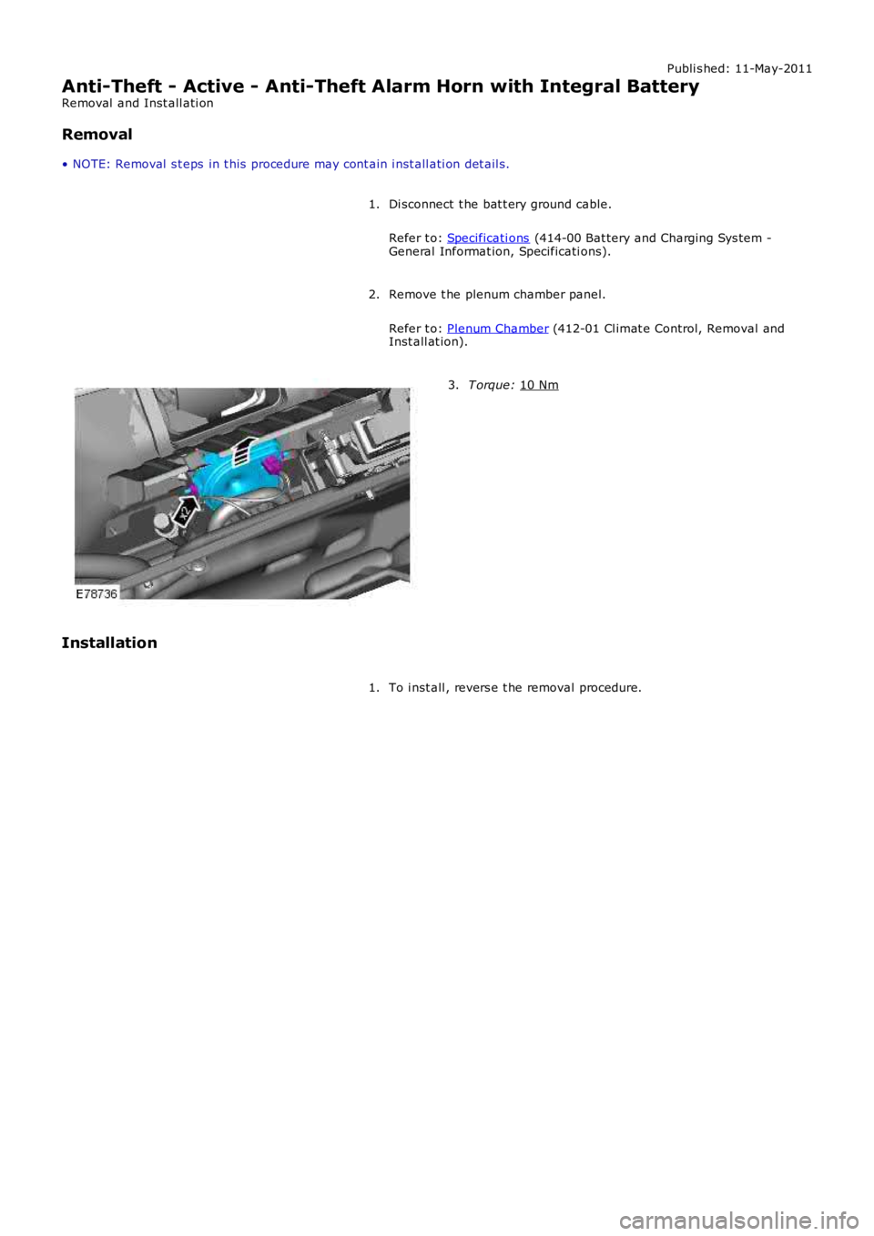
Anti-Theft - Active - Anti-Theft Alarm Horn with Integral Battery
Removal and Inst all ati on
Removal
• NOTE: Removal s t eps in t his procedure may cont ain i nst all ati on det ail s.
Di sconnect t he bat t ery ground cable.
Refer t o: Specificati ons (414-00 Bat tery and Charging Sys tem -
General Informat ion, Specificati ons).
1.
Remove t he plenum chamber panel.
Refer t o: Plenum Chamber (412-01 Cl imat e Control, Removal and
Inst all at ion).
2. T orque:
10 Nm 3.
Installation To i nst all , revers e t he removal procedure.
1.
Page 2073 of 3229
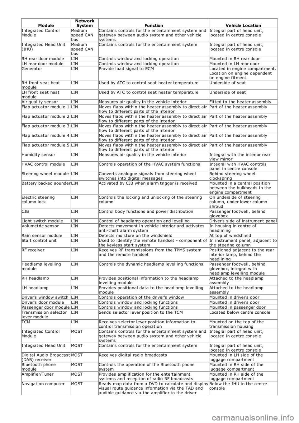
ModuleNetw orkSystemFunctionVehicle Location
Integrat ed Cont rolModuleMedi umspeed CANbus
Contains controls for the ent ert ai nment sys t em andgateway between audio s ys t em and ot her vehicles ys t ems
Int egral part of head uni t,located i n cent re cons ole
Integrat ed Head Unit(IHU)Medi umspeed CANbus
Contains controls for the ent ert ai nment sys t emInt egral part of head uni t,located i n cent re cons ole
RH rear door moduleLINControl s wi ndow and locki ng operati onMount ed i n RH rear door
LH rear door moduleLINControl s wi ndow and locki ng operati onMount ed i n LH rear doorGenerat orLINProvide l oad s ignal t o ECMLocat ed in engine compart ment .Locat ion on engine dependenton engine fit ment.
RH front s eat heatmoduleLINUs ed by ATC t o cont rol s eat heat er temperat ureUnders ide of s eat
LH front s eat heatmoduleLINUs ed by ATC t o cont rol s eat heat er temperat ureUnders ide of s eat
Air quali ty sens orLINMeasures air qualit y i n t he vehi cl e int eri orFit ted t o t he heater as sembl y
Flap act uat or modul e 1LINMoves fl aps wit hi n t he heat er ass embl y to direct airfl ow t o different parts of t he i nt eri orPart of t he heat er as s embly
Flap act uat or modul e 2LINMoves fl aps wit hi n t he heat er ass embl y to direct airfl ow t o different parts of t he i nt eri orPart of t he heat er as s embly
Flap act uat or modul e 3LINMoves fl aps wit hi n t he heat er ass embl y to direct airfl ow t o different parts of t he i nt eri orPart of t he heat er as s embly
Flap act uat or modul e 4LINMoves fl aps wit hi n t he heat er ass embl y to direct airfl ow t o different parts of t he i nt eri orPart of t he heat er as s embly
Flap act uat or modul e 5LINMoves fl aps wit hi n t he heat er ass embl y to direct airfl ow t o different parts of t he i nt eri orPart of t he heat er as s embly
Humi di ty sens orLINMeasures air qualit y i n t he vehi cl e int eri orInt egral wit h t he int eri or rearview mirror
HVAC control modul eLINControl s operat ion of t he HVAC s ys t em funct ionsInt egral wit h HVAC controlspanel i n cent re cons ole
St eering wheel moduleLINConverts analogue s ignals from s teering wheels wit ches i nto di git al mes s agesBehi nd s teering wheelclocks pri ngBatt ery backed s ounderLINActi vat ed by CJB when alarm t ri gger i s receivedMount ed i n a central pos it ionbetween t he bulkheads i n t heengi ne compartment
Electric st eeringcolumn l ockLINControl s t he locking and unlocki ng of the st eeri ngcol umnOn unders ide of s t eeringcol umn, under lower columns hroud
CJBLINControl body funct ions and power di st ributi onPass enger footwell , behi ndglovebox
Light s wit ch moduleLINControl of headlamp operat ion and l evel lingDri ver's s i de of ins trument panelVolumet ri c s ens orLINDetects movement i n vehicle i nterior and act ivatesanti -t heft alarm s ys temIn hous ing in centre ofheadl ining
Rain sens or modul eLINDetects mois t ure on t he wi nds hiel dAt top of windshi el dSt art cont rol unitLINUs ed to identi fy t he remote hands et - component oft he keyles s s t art s yst emIn ins trument panel, adjacent tothe st eeri ng col umnRF recei verLINRecei ves RF trans mi s si ons from t he TPMS s yst emand t he remot e hands etPosi ti oned adjacent t o the rearint erior l amp, behi nd theheadl ining
Headlamp l evel li ngmoduleLINControl s t he dynami c headl amp l evell ing funct ionsPass enger footwell , behi ndglovebox, int egral wit hheadl amp levell ing module
RH headlampLINProvides pos it ional i nformati on to the headlamplevell ing moduleAtt ached t o t he headl ampass embl y
LH headlampLINProvides pos it ional dat a t o t he headlamp levell ingmoduleAtt ached t o t he headl ampass embl y
Driver's window s wi tchLINControl s operat ion of t he driver's wi ndowMount ed i n dri ver's door
Driver's door moduleLINControl s wi ndow and locki ng functi onsMount ed i n dri ver's doorPas senger door moduleLINControl s wi ndow and locki ng functi onsMount ed i n pass enger door
Trans mi ss ion sel ect orl ever moduleLINSends sel ect or l ever pos it ion t o t he TCMLocat ed bel ow centre cons ole
TCMLINRecei ves s elect or l ever pos it ion i nformat ion tocont rol t rans mis s ion operat ionMount ed on t he t op of thetransmis s ion housi ngIntegrat ed Cont rolModuleMOSTContains controls for the ent ert ai nment sys t em andgateway between audio s ys t em and ot her vehicles ys t ems
Int egral part of head uni t,located i n cent re cons ole
Integrat ed Head UnitMOSTContains controls for the ent ert ai nment sys t emInt egral part of head uni t,located i n cent re cons oleDi gi tal Audio Broadcas t(DAB) recei verMOSTRecei ves di git al radi o broadcast sMount ed i n LH s ide of t heluggage compartmentBluet oot h phonemoduleMOSTControl s t he operati on of the Bl uet ooth phones ys t emMount ed i n RH s i de of theluggage compartment
Ampl ifi er/TunerMOSTProvides ampl ifi cat ion for the ent ert ainments ys t ems and recepti on of radio RF broadcas t sMount ed i n RH s i de of theluggage compartment
Navigati on comput erMOSTReads map data from a DVD t o cal cul ate and di spl ayvis ual route gui dance i nformat ion vi a t he TAD andaudi ble gui dance via the ampl ifier to the driver
Below t he IHU i n t he cent recons ole
Page 2313 of 3229
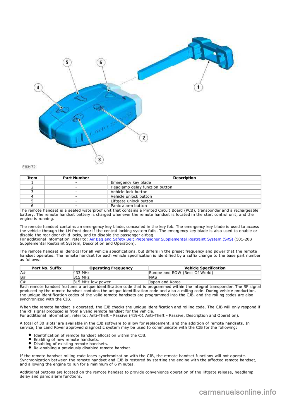
ItemPart NumberDescription1-Emergency key bl ade2-Headl amp delay funct ion but ton3-Vehicl e l ock button4-Vehicl e unlock button5-Li ftgate unlock butt on6-Panic alarm buttonThe remote hands et is a seal ed wat erproof uni t t hat contains a Printed Ci rcuit Board (PCB), transponder and a rechargeablebattery. The remote hands et batt ery i s charged whenever the remote hands et is located i n the s tart cont rol unit , and t heengi ne is running.
The remote hands et cont ai ns an emergency key blade, conceal ed in t he key fob. The emergency key bl ade i s us ed to acces sthe vehicle through the LH front door i f t he central locki ng syst em fai ls. The emergency key bl ade is als o us ed t o enable ordis able t he rear door chil d locks , and t o dis able t he pas senger ai rbag.For addit ional informat ion, refer t o: Ai r Bag and Safet y Belt Pretens ioner Supplement al Rest raint Sys tem (SRS) (501-20BSupplemental Res traint Sys tem, Des cription and Operat ion).
The remote hands et is identi cal for all vehicl e s peci ficat ions, but di ffers in t he pres et frequency and power that the remotehandset operates. The remot e handset for each vehicle specificat ion is ident ifi ed by a s uffix change to the base part numberas follows:
Part No. SuffixOperating FrequencyVehicle SpecificationA#433 MHzEurope and ROW (Rest Of W orld)B#315 MHzNASC#315 MHz low powerJapan and KoreaEach remot e handset features a uni que ident ifi cation code that is programmed within t he integral trans ponder. The RF si gnalproduced by t he remot e handset contains t he uni que ident ifi cation code and also a rolli ng code. Duri ng vehicl e product ion,the unique identification codes of the valid remot e handsets are programmed int o the CJB, and the roll ing codes are al sosynchronized wi th the CJB.
W hen the remote handset is operat ed, t he CJB checks t he unique i dent ificat ion and rol ling code. The CJB will only respond ifthe RF si gnal produced is from a val id remote hands et for the vehicle.For addit ional informat ion, refer t o: Anti -Theft - Pas si ve (419-01 Anti -Theft - Pas si ve, Des cript ion and Operati on).
A tot al of 30 'sl ots ' are availabl e in the CJB s oftware to al low for repl acement, and the addi tion of remote hands et s. Inservi ce, t he Land Rover approved di agnost ic system may be us ed to communicat e wit h the CJB for the followi ng:
Identi ficati on of remote handset all ocat ion wit hin t he CJB.Enabli ng of new remot e handsets .Disabl ing of exist ing remote handsets .Re-enabling a previ ously disabled remot e handset.
If the remote hands et rolling code l os es synchronizati on with t he CJB, t he remot e handset funct ions will not operate.Synchronizati on between the remote hands et and CJB is rest ored by s tart ing t he engine wit h t he affect ed remot e handset,and all owing the engine to run for a minimum of 6 mi nutes.
Addi tional buttons are located on the remote hands et to provide convenience operati on of t he li ftgat e rel ease, headlampdelay and panic al arm functions .
Page 2327 of 3229
4
1
2
3
4
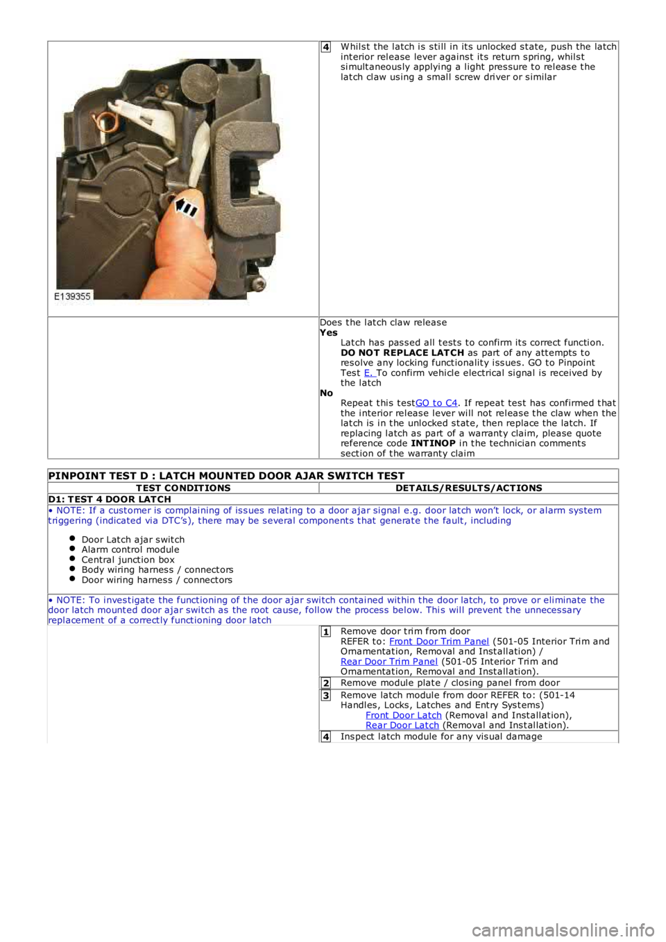
W hil s t the l atch i s s ti ll in it s unlocked s t ate, push the latchint erior rel ease lever agains t it s return s pring, whil s tsi mult aneous ly applyi ng a l ight pres sure t o rel eas e t helat ch cl aw us ing a smal l screw dri ver or s imilar
Does t he l at ch claw releas eYesLat ch has pas s ed all t est s t o confirm it s correct functi on.DO NO T REPLACE LAT CH as part of any att empts t ores olve any locking funct ionalit y i ss ues . GO t o PinpointTes t E. To confirm vehi cl e electrical si gnal i s received bythe l atchNoRepeat t hi s t estGO t o C4. If repeat tes t has confirmed t hatthe i nterior rel eas e l ever wi ll not rel eas e t he claw when thelat ch is i n t he unl ocked s t at e, then replace the latch. Ifreplacing l atch as part of a warrant y claim, please quot ereference code INT INOP i n t he technician comment ssect ion of t he warrant y claim
PINPOINT TEST D : LATCH MOUNTED DOOR AJAR SWITCH TEST
T EST CO NDIT IONSDET AILS/RESULT S/ACT IONS
D1: T EST 4 DOOR LAT CH• NOTE: If a cust omer is compl ai ning of is s ues rel at ing to a door ajar si gnal e.g. door lat ch won’t lock, or al arm sys temt ri ggering (indicated vi a DTC’s ), t here may be s everal component s t hat generat e t he fault , including
Door Lat ch ajar s wit chAlarm control modul eCentral junct ion boxBody wiring harnes s / connect orsDoor wiring harnes s / connect ors
• NOTE: To i nves t igate the funct ioning of t he door ajar swi tch contai ned wit hin t he door latch, to prove or eli minate thedoor latch mount ed door ajar swi tch as the root caus e, foll ow t he proces s bel ow. This wil l prevent t he unneces saryrepl acement of a correct ly funct ioning door lat chRemove door t ri m from doorREFER t o: Front Door Trim Panel (501-05 Interior Tri m andOrnamentat ion, Removal and Inst all ati on) /Rear Door Tri m Panel (501-05 Int erior Tri m andOrnamentat ion, Removal and Inst all ati on).
Remove modul e plat e / clos ing panel from door
Remove latch modul e from door REFER to: (501-14Handl es , Locks , Latches and Ent ry Sys t ems)Front Door Latch (Removal and Inst all at ion),Rear Door Lat ch (Removal and Ins t al lat ion).
Ins pect l atch module for any vis ual damage
Page 2723 of 3229

Contents
3
R
Quick start
QUICK START ................................................... 7
Filling station information
FILLING STATION INFORMATION................... 33
Introduction
SYMBOLS GLOSSARY .................................... 35
LABEL LOCATIONS ......................................... 35
HEALTH AND SAFETY ..................................... 36
DATA RECORDING.......................................... 37
DISABILITY MODIFICATIONS ......................... 37
PARTS AND ACCESSORIES ............................ 37
Keys and remote controls
USING THE KEY .............................................. 40
GENERAL INFORMATION ON RADIO
FREQUENCIES ................................................ 40
USING THE REMOTE CONTROL ..................... 41
Locks
LOCKING AND UNLOCKING ............................ 44
Alarm
ARMING THE ALARM ..................................... 45
DISARMING THE ALARM ............................... 46
Seats
SITTING IN THE CORRECT POSITION ............ 47
MANUAL SEATS ............................................. 48
ELECTRIC SEATS ............................................ 49
HEAD RESTRAINTS ........................................ 51
REAR SEATS................................................... 51
HEATED SEATS............................................... 53
Seat belts
PRINCIPLE OF OPERATION ............................ 54
SEAT BELT REMINDER ................................... 55
FASTENING THE SEAT BELTS ........................ 56
SEAT BELT HEIGHT ADJUSTMENT................. 56
USING SEAT BELTS DURI NG PREGNANCY .... 57
Supplementary restraints system
PRINCIPLE OF OPERATION ............................ 58
AIRBAG WARNING LAMP ............................... 61
DISABLING THE PASSENGER AIRBAG ........... 62
AIRBAG SERVICE INFORMATION ................... 63
Child safety
CHILD SEATS ................................................. 64
BOOSTER CUSHIONS ..................................... 66
ISOFIX ANCHOR POINTS................................ 67
CHILD SAFETY LOCKS ................................... 69
Steering wheel
ADJUSTING THE STEERING WHEEL .............. 70
AUDIO CONTROL ........................................... 70
Lighting
LIGHTING CONTROL ...................................... 72
FRONT FOG LAMPS........................................ 72
REAR FOG LAMPS.......................................... 73
ADJUSTING THE HEADLAMPS....................... 73
HEADLAMP LEVELLING ................................. 73
HAZARD WARNING FLASHERS...................... 74
ADAPTIVE FRONT LIGHTING SYSTEM (AFS) . 74
DIRECTION INDICATORS ............................... 75
INTERIOR LAMPS .......................................... 76
APPROACH LAMPS ........................................ 76
CHANGING A BULB ........................................ 77
BULB SPECIFICATION CHART ........................ 86
Wipers and washers
WINDSCREEN WIPERS .................................. 87
RAIN SENSOR ................................................ 87
WINDSCREEN WASHERS............................... 88
HEADLAMP WASHERS................................... 88
REAR WINDOW WIPER AND WASHERS ........ 89
ADJUSTING THE WINDSCREEN WASHER JETS .
89
CHECKING THE WIPER BLADES .................... 90
CHANGING THE WIPER BLADES.................... 90
Windows and mirrors
ELECTRIC WINDOWS ..................................... 93
EXTERIOR MIRRORS ..................................... 94
ELECTRIC EXTERIOR MIRRORS .................... 95
INTERIOR MIRROR ........................................ 96
Instruments
INSTRUMENT PANEL OVERVIEW .................. 97
Information displays
TRIP COMPUTER ........................................... 99
INFORMATION MESSAGES ............................ 99
Page 2727 of 3229
7
Quick start
R
Quick startQUICK START
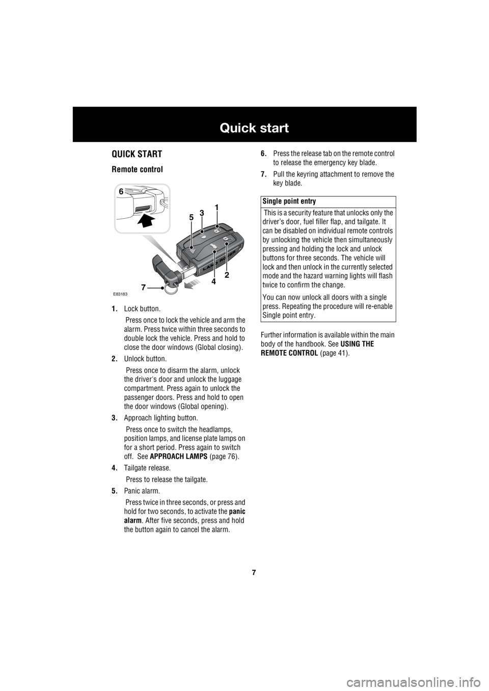
Remote control
1. Lock button.
Press once to lock the vehicle and arm the
alarm. Press twice within three seconds to
double lock the vehicle. Press and hold to
close the door windows (Global closing).
2. Unlock button.
Press once to disarm the alarm, unlock
the driver's door and unlock the luggage
compartment. Press again to unlock the
passenger doors. Press and hold to open
the door windows (Global opening).
3. Approach lighting button.
Press once to switch the headlamps,
position lamps, and license plate lamps on
for a short period. Press again to switch
off. See APPROACH LAMPS (page 76).
4. Tailgate release.
Press to release the tailgate.
5. Panic alarm.
Press twice in three seconds, or press and
hold for two seconds, to activate the panic
alarm . After five seconds, press and hold
the button again to cancel the alarm. 6.
Press the release tab on the remote control
to release the emergency key blade.
7. Pull the keyring attachment to remove the
key blade.
Further information is available within the main
body of the handbook. See USING THE
REMOTE CONTROL (page 41).
6
31
E83183
2
74
5
Single point entry
This is a security feature that unlocks only the
driver’s door, fuel fille r flap, and tailgate. It
can be disabled on indi vidual remote controls
by unlocking the vehicle then simultaneously
pressing and holding th e lock and unlock
buttons for three sec onds. The vehicle will
lock and then unlock in the currently selected
mode and the hazard wa rning lights will flash
twice to confirm the change.
You can now unlock all doors with a single
press. Repeating the pr ocedure will re-enable
Single point entry.
Page 2760 of 3229
Keys and remote controls
40
L
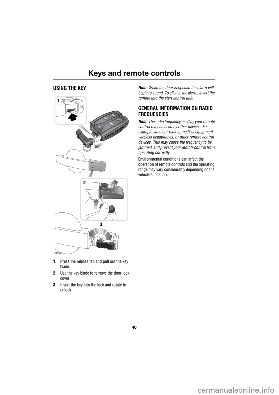
Keys and remote controlsUSING THE KEY
1. Press the release tab and pull out the key
blade.
2. Use the key blade to remove the door lock
cover.
3. Insert the key into the lock and rotate to
unlock. Note:
When the door is opened the alarm will
begin to sound. To silenc e the alarm, insert the
remote into the start control unit.
GENERAL INFORMATION ON RADIO
FREQUENCIES
Note: The radio frequency used by your remote
control may be used by other devices. For
example: amateur radios , medical equipment,
wireless headphones, or other remote control
devices. This may cause the frequency to be
jammed, and prevent your remote control from
operating correctly.
Environmental conditions can affect the
operation of remote cont rols and the operating
range may vary considerably depending on the
vehicle's location.
1
E80882
2
3
Page 2761 of 3229
41
Keys and remote controls
R
USING THE REMOTE CONTROL
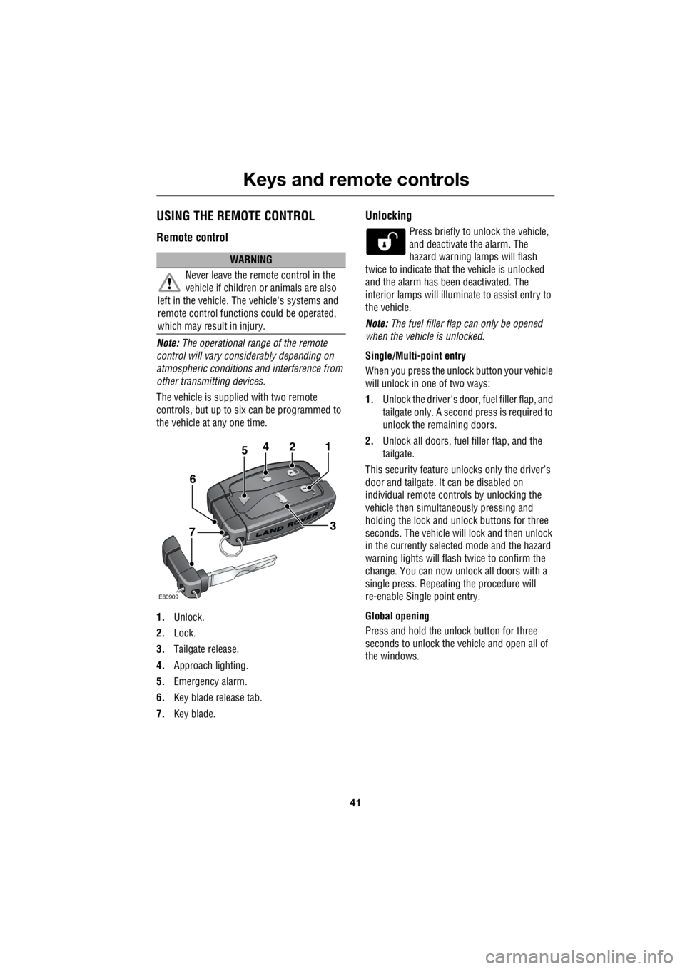
Remote control
Note: The operational range of the remote
control will vary considerably depending on
atmospheric conditions and interference from
other transmitting devices.
The vehicle is supplied with two remote
controls, but up to six can be programmed to
the vehicle at any one time.
1. Unlock.
2. Lock.
3. Tailgate release.
4. Approach lighting.
5. Emergency alarm.
6. Key blade release tab.
7. Key blade.
Unlocking
Press briefly to unlock the vehicle,
and deactivate the alarm. The
hazard warning lamps will flash
twice to indicate that the vehicle is unlocked
and the alarm has been deactivated. The
interior lamps will illuminate to assist entry to
the vehicle.
Note: The fuel filler flap can only be opened
when the vehicle is unlocked.
Single/Multi- point entry
When you press the unlock button your vehicle
will unlock in one of two ways:
1. Unlock the driver's door, fuel filler flap, and
tailgate only. A second press is required to
unlock the remaining doors.
2. Unlock all doors, fuel filler flap, and the
tailgate.
This security feature unlocks only the driver’s
door and tailgate. It can be disabled on
individual remote controls by unlocking the
vehicle then simultaneously pressing and
holding the lock and unlock buttons for three
seconds. The vehicle will lock and then unlock
in the currently selected mode and the hazard
warning lights will flas h twice to confirm the
change. You can now unlock all doors with a
single press. Repeating the procedure will
re-enable Single point entry.
Global opening
Press and hold the unlock button for three
seconds to unlock the ve hicle and open all of
the windows.
WARNING
Never leave the remote control in the
vehicle if children or animals are also
left in the vehicle. The vehicle's systems and
remote control functions could be operated,
which may result in injury.
2
E80909
451
3
6
7