2006 LAND ROVER FRELANDER 2 remote start
[x] Cancel search: remote startPage 2060 of 3229
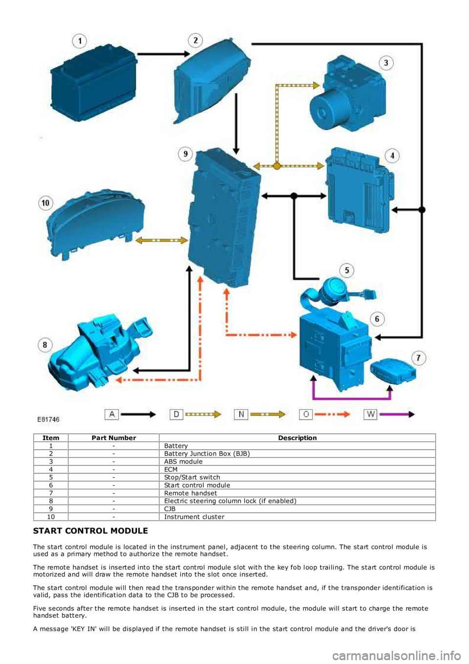
ItemPart NumberDescription
1-Bat t ery2-Bat t ery Junct ion Box (BJB)
3-ABS module
4-ECM5-St op/St art s wit ch
6-St art control modul e
7-Remot e handset8-El ect ri c s teering column l ock (i f enabled)
9-CJB
10-Ins trument cl ust er
START CONTROL MODULE
The s tart cont rol module i s located in t he ins t rument panel , adjacent t o t he s teeri ng col umn. The st art control modul e i sus ed as a pri mary method t o aut horize t he remot e handset .
The remot e handset i s ins ert ed int o t he s tart cont rol module s l ot wit h the key fob loop trai li ng. The s t art cont rol module ismot orized and wi ll draw the remot e hands et int o t he s lot once ins ert ed.
The s tart cont rol module wi ll t hen read t he t rans ponder wit hin t he remote hands et and, if t he t rans ponder identi fi cat ion i svalid, pas s the identi ficat ion data to the CJB t o be proces s ed.
Five s econds after t he remot e hands et is ins ert ed in the s t art cont rol module, t he module will s t art t o charge t he remot ehands et batt ery.
A mes s age 'KEY IN' wil l be dis played if t he remot e handset i s s ti ll i n the st art control modul e and t he dri ver's door is
Page 2174 of 3229
3
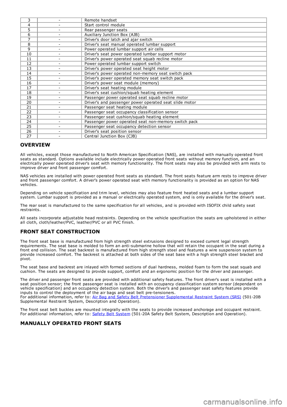
-Remote hands et
4 -Start control modul e
5 -Rear pas senger s eat s
6 -Auxi liary Junct ion Box (AJB)
7 -Dri ver's door lat ch and ajar s wit ch
8 -Dri ver's s eat manual operat ed lumbar s upport
9 -Power operat ed lumbar s upport air cel ls
10 -Dri ver's s eat power operat ed lumbar s upport motor
11 -Dri ver's power operated s eat s quab recline motor
12 -Power operat ed lumbar s upport swit ch
13 -Dri ver's power operated s eat height motor
14 -Dri ver's power operated non-memory s eat s wit ch pack
15 -Dri ver's power operated memory s eat s wit ch pack
16 -Dri ver's power s eat modul e (memory)
17 -Dri ver's s eat heat ing modul e
18 -Dri ver's s eat cus hion/squab heati ng element
19 -Pas s enger power operated s eat s quab recl ine motor
20 -Dri ver's and pas senger power operat ed s eat s l ide mot or
21 -Pas s enger s eat heat ing modul e
22 -Pas s enger s eat occupancy clas s ifi cat ion sens or
23 -Pas s enger s eat cus hion/s quab heati ng element
24 -Pas s enger power operated s eat non-memory s wit ch pack
25 -Pas s enger s eat occupancy detecti on s ens or
26 -Dri ver's s eat pos i ti on s ens or
27 -Cent ral Junct ion Box (CJB)
OVERVIEW
All vehicles , except thos e manufactured to Nort h American Specificati on (NAS), are i ns tall ed wit h manuall y operated front
s eat s as s t andard. Opt ions available include electricall y power operat ed front s eat s wi thout memory functi on, and an
electricall y power operat ed dri ver's s eat wit h memory funct ionalit y. The front s eats may als o be provi ded wit h arm rest s t o
improve dri ver and front pass enger comfort .
NAS vehicles are ins tal led wi th power operat ed front seat s as s tandard. The front se at s feat ure arm res ts t o i mprove driver
and front pas s enger comfort. A dri ver's power operated s eat wit h memory funct ionalit y i s provided as an opt ion for NAS
vehi cl es.
Dependi ng on vehi cl e s peci fi cat ion and t ri m l evel , vehi cl es may als o feature front h eat ed s eat s and a l umbar support
s ys t em. Lumbar s upport is provided as a manual or electrically operat ed s yst em, and i s onl y available for t he dri ver's s eat.
The rear s eat is manufact ured t o t he s ame s pecificati on for al l vehicles , and is pro vided wi th ISOFIX chi ld s afet y s eat
res t raint s .
All s eats i ncorporate adjust able head rest rai nt s . Depending on the vehicle specifica ti on the seat s are uphols t ered in eit her
all clot h, cl ot h/l eat her/PVC, l eather/PVC or all PVC finis h.
FRONT SEAT CONSTRUCTION
The front seat bas e is manufact ured from high s t rength st eel ext rus ions des igned to exceed current l egal s trengt h
requirements . The s eat bas e i s molded t o form an anti -s ubmari ne hollow that wi ll ret ain t he occupant in the s eat during a
front end col lis i on. The s eat backres t is manufact ured from high st rength s teel and features a wi re sus pens i on sys t em t o
provide i ncreased comfort . The backres t is at t ached at both si des of t he s eat bas e w it h a high st rengt h s teel bracket and
pivot.
The s eat bas e and backrest are i nl ayed wit h formed s ect ions of dual hardnes s , molded foam t o form the s eat s quab and
cus hion. The s eats are desi gned to provide s upport, comfort and an ergonomic pos it io n for t he driver and pass enger.
The dri ver and pas senger front seat s are provi ded wit h addit ional safet y feat ures . T he front driver's s eat is i nst all ed wit h a
s eat pos it ion s ens or; t he front pas s enger s eat is i ns t alled wit h an occupancy cl ass i ficati on s yst em s ens or (dependant on
vehi cl e s peci fi cat ion) and an occupancy det ect ion s ys tem. Bot h t he driver's and pas s enger seat s afet y feat ures provide
inputs to cont rol the deployment of the ai r bags and seat belt pre-t ens ioners .
For addit ional informat ion, refer t o: Air Bag and Safet y Belt Pretens ioner Supplement al Res traint Syst em (SRS) (501-20B
Suppl ement al Rest rai nt Sys tem, Des cri pti on and Operati on).
The front seat belt buckl es are mount ed i nt egrall y wi th t he s eats t o provi de increas ed anchorage and occupant res t raint .
For addit ional informat ion, refer t o: Safety Bel t Syst em (501-20A Safet y Belt Sys tem, Des cript ion and O perati on).
MANUALLY OPERATED FRONT SEATS
Page 2307 of 3229
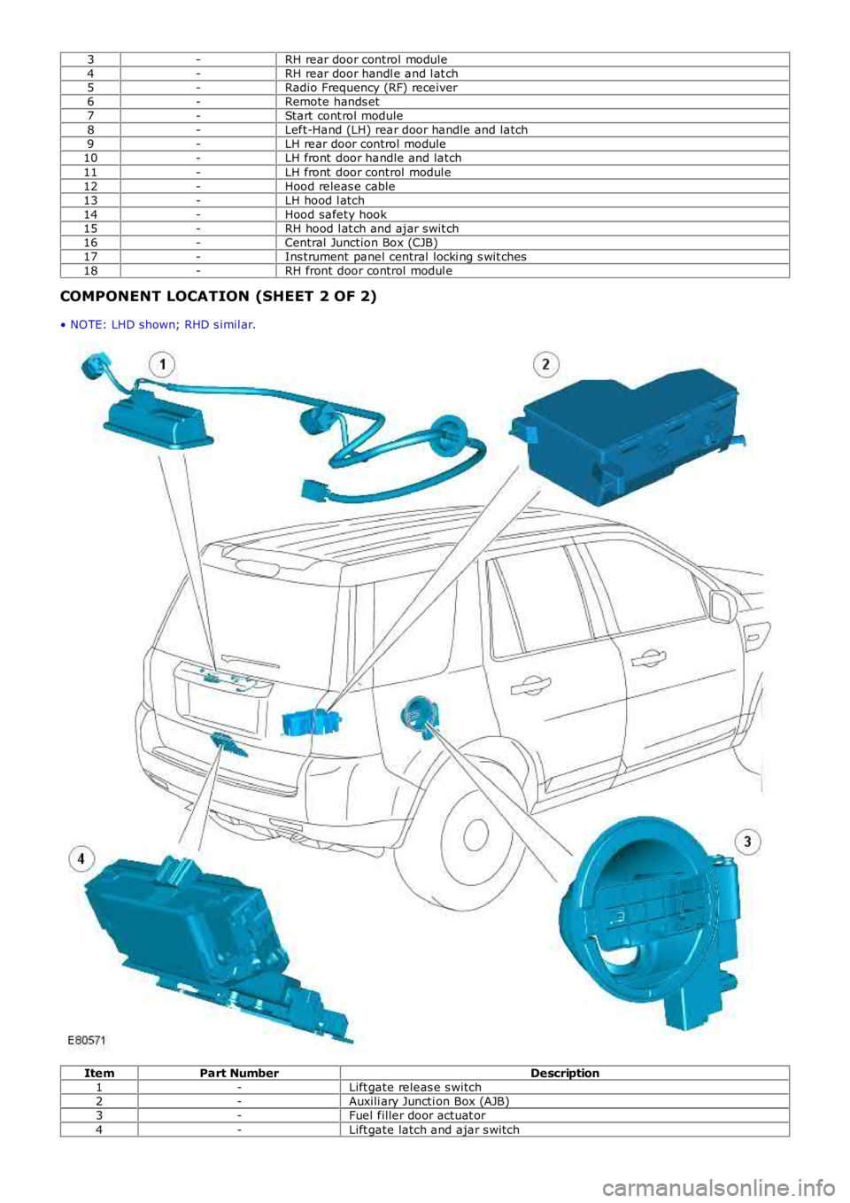
3-RH rear door control module4-RH rear door handl e and l at ch5-Radio Frequency (RF) receiver6-Remote hands et7-Start cont rol module8-Left-Hand (LH) rear door handle and latch9-LH rear door control module10-LH front door handle and latch
11-LH front door control modul e12-Hood releas e cable13-LH hood l atch14-Hood safety hook15-RH hood l at ch and ajar swit ch16-Central Junction Box (CJB)17-Ins trument panel central locki ng s wit ches18-RH front door control modul e
COMPONENT LOCATION (SHEET 2 OF 2)
• NOTE: LHD shown; RHD s imil ar.
ItemPart NumberDescription1-Lift gate releas e s witch2-Auxili ary Juncti on Box (AJB)3-Fuel filler door actuat or
4-Lift gate latch and ajar s witch
Page 2317 of 3229
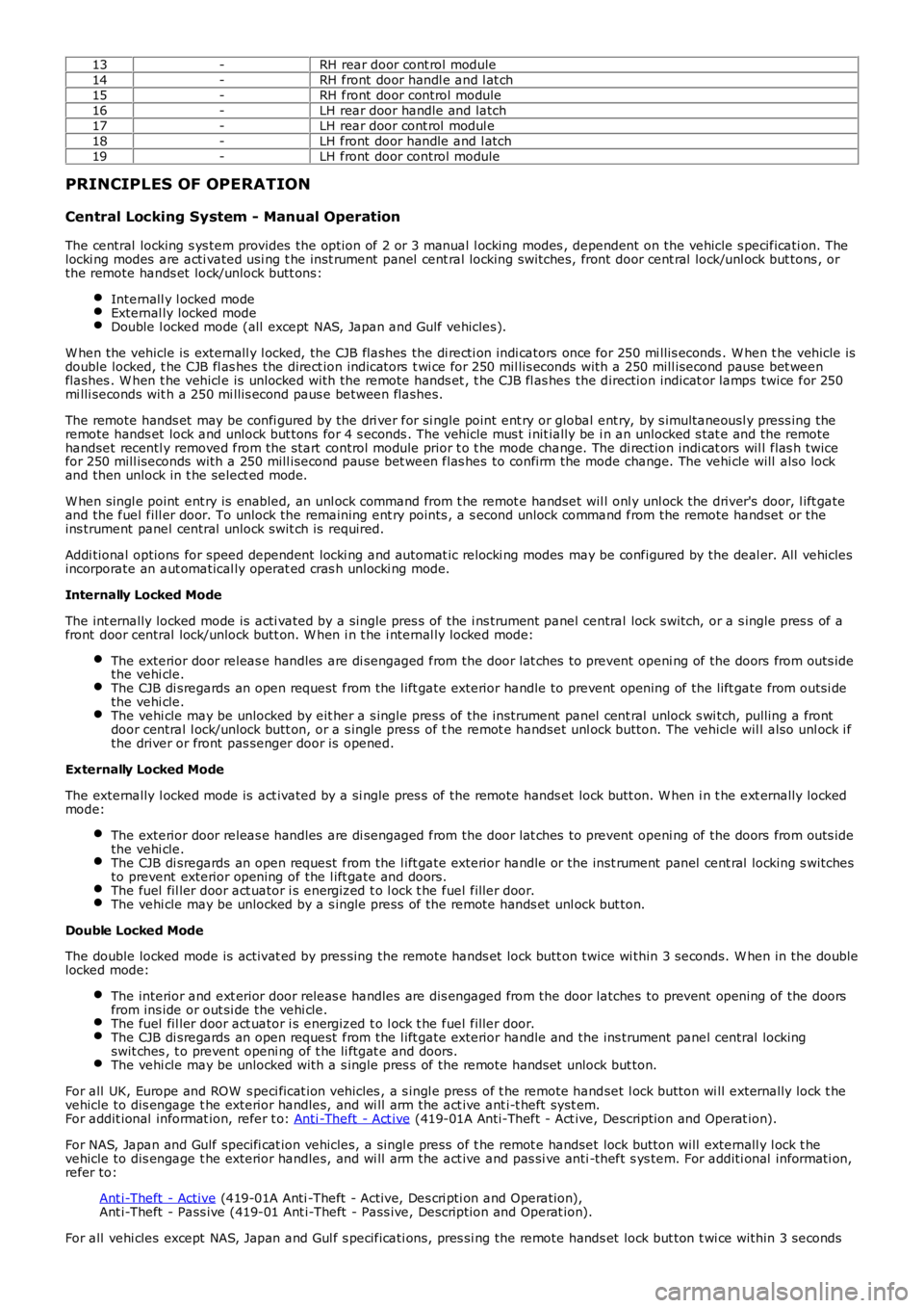
13-RH rear door cont rol module14-RH front door handl e and l at ch15-RH front door control module16-LH rear door handle and latch17-LH rear door cont rol modul e18-LH front door handle and l atch19-LH front door control module
PRINCIPLES OF OPERATION
Central Locking System - Manual Operation
The central locking s ys tem provides the option of 2 or 3 manual l ocking modes , dependent on the vehicle s pecificati on. Thelocki ng modes are acti vated usi ng t he inst rument panel cent ral locking switches, front door cent ral lock/unl ock but tons , orthe remote hands et lock/unlock butt ons:
Internall y l ocked modeExternal ly locked modeDouble l ocked mode (all except NAS, Japan and Gulf vehicles).
W hen the vehicle is externall y l ocked, the CJB flashes the di recti on indi cators once for 250 mi llis econds . W hen t he vehicle isdouble locked, t he CJB fl as hes the direct ion indicators t wi ce for 250 mil lis econds with a 250 mill isecond pause bet weenflashes . W hen t he vehicl e is unlocked with the remote hands et , t he CJB fl as hes the direction indicat or lamps twice for 250mi lli seconds wit h a 250 mi llis econd paus e between flashes.
The remote hands et may be confi gured by the dri ver for si ngle point ent ry or global ent ry, by s imultaneousl y press ing theremote hands et lock and unlock but tons for 4 s econds . The vehicle mus t i nit ially be i n an unlocked s tat e and the remotehandset recentl y removed from the start control module prior t o t he mode change. The di rection indi cat ors wil l flas h twicefor 250 mill iseconds with a 250 mill isecond pause bet ween flas hes to confirm the mode change. The vehi cle will also lockand then unlock in t he select ed mode.
W hen singl e point ent ry is enabled, an unl ock command from t he remot e handset wil l onl y unl ock the driver's door, l ift gateand the fuel fill er door. To unlock the remaining ent ry points , a s econd unlock command from the remote handset or theins trument panel central unlock swit ch is required.
Addi tional options for speed dependent locki ng and automat ic relocki ng modes may be configured by the deal er. All vehiclesincorporate an aut omatical ly operat ed cras h unlocki ng mode.
Internally Locked Mode
The int ernally locked mode is acti vated by a single pres s of the i ns trument panel central lock switch, or a s ingle pres s of afront door central lock/unlock butt on. W hen i n t he i nternal ly locked mode:
The exterior door releas e handles are di sengaged from the door lat ches t o prevent openi ng of the doors from outs idethe vehi cle.The CJB di sregards an open request from the l ift gate exterior handle to prevent opening of the lift gate from outsi dethe vehi cle.The vehi cle may be unlocked by eit her a s ingle press of the instrument panel cent ral unlock s wi tch, pulling a frontdoor central l ock/unlock butt on, or a s ingle press of t he remot e handset unl ock button. The vehicle wil l also unl ock i fthe driver or front pas senger door is opened.
Externally Locked Mode
The externally l ocked mode is act ivated by a si ngle pres s of the remote hands et lock butt on. W hen i n t he ext ernally lockedmode:
The exterior door releas e handles are di sengaged from the door lat ches t o prevent openi ng of the doors from outs idethe vehi cle.The CJB di sregards an open request from the l ift gate exterior handle or the inst rument panel cent ral locking s witchesto prevent exterior opening of the l ift gate and doors.The fuel fil ler door act uator i s energized t o l ock t he fuel filler door.The vehi cle may be unlocked by a s ingle press of the remote hands et unl ock but ton.
Double Locked Mode
The double locked mode is activat ed by pres sing the remote hands et lock butt on twice wi thin 3 seconds. W hen in the doublelocked mode:
The interior and ext erior door releas e handles are dis engaged from the door latches to prevent opening of the doorsfrom ins ide or out si de the vehi cle.The fuel fil ler door act uator i s energized t o l ock t he fuel filler door.The CJB di sregards an open request from the l ift gate exterior handle and the ins trument panel central lockingswit ches , t o prevent openi ng of t he li ftgat e and doors.The vehi cle may be unlocked with a s ingle pres s of the remote hands et unlock but ton.
For all UK, Europe and ROW s peci ficat ion vehicles , a s ingl e press of t he remot e handset l ock button wi ll externally lock t hevehicle to dis engage t he exterior handles, and wi ll arm the act ive ant i-t heft syst em.For addit ional informat ion, refer t o: Anti -Theft - Act ive (419-01A Anti-Theft - Act ive, Description and Operat ion).
For NAS, Japan and Gulf specifi cat ion vehicles, a singl e press of t he remot e handset lock button will externall y l ock t hevehicle to dis engage t he exterior handles, and wi ll arm the act ive and pas si ve anti -theft s ys tem. For additi onal informati on,refer to:
Ant i-Theft - Active (419-01A Anti -Theft - Active, Des cri pti on and Operation),Ant i-Theft - Pass ive (419-01 Ant i-Theft - Pass ive, Description and Operat ion).
For all vehi cles except NAS, Japan and Gul f s pecificati ons, pres si ng the remote hands et lock but ton t wi ce within 3 seconds
Page 2723 of 3229

Contents
3
R
Quick start
QUICK START ................................................... 7
Filling station information
FILLING STATION INFORMATION................... 33
Introduction
SYMBOLS GLOSSARY .................................... 35
LABEL LOCATIONS ......................................... 35
HEALTH AND SAFETY ..................................... 36
DATA RECORDING.......................................... 37
DISABILITY MODIFICATIONS ......................... 37
PARTS AND ACCESSORIES ............................ 37
Keys and remote controls
USING THE KEY .............................................. 40
GENERAL INFORMATION ON RADIO
FREQUENCIES ................................................ 40
USING THE REMOTE CONTROL ..................... 41
Locks
LOCKING AND UNLOCKING ............................ 44
Alarm
ARMING THE ALARM ..................................... 45
DISARMING THE ALARM ............................... 46
Seats
SITTING IN THE CORRECT POSITION ............ 47
MANUAL SEATS ............................................. 48
ELECTRIC SEATS ............................................ 49
HEAD RESTRAINTS ........................................ 51
REAR SEATS................................................... 51
HEATED SEATS............................................... 53
Seat belts
PRINCIPLE OF OPERATION ............................ 54
SEAT BELT REMINDER ................................... 55
FASTENING THE SEAT BELTS ........................ 56
SEAT BELT HEIGHT ADJUSTMENT................. 56
USING SEAT BELTS DURI NG PREGNANCY .... 57
Supplementary restraints system
PRINCIPLE OF OPERATION ............................ 58
AIRBAG WARNING LAMP ............................... 61
DISABLING THE PASSENGER AIRBAG ........... 62
AIRBAG SERVICE INFORMATION ................... 63
Child safety
CHILD SEATS ................................................. 64
BOOSTER CUSHIONS ..................................... 66
ISOFIX ANCHOR POINTS................................ 67
CHILD SAFETY LOCKS ................................... 69
Steering wheel
ADJUSTING THE STEERING WHEEL .............. 70
AUDIO CONTROL ........................................... 70
Lighting
LIGHTING CONTROL ...................................... 72
FRONT FOG LAMPS........................................ 72
REAR FOG LAMPS.......................................... 73
ADJUSTING THE HEADLAMPS....................... 73
HEADLAMP LEVELLING ................................. 73
HAZARD WARNING FLASHERS...................... 74
ADAPTIVE FRONT LIGHTING SYSTEM (AFS) . 74
DIRECTION INDICATORS ............................... 75
INTERIOR LAMPS .......................................... 76
APPROACH LAMPS ........................................ 76
CHANGING A BULB ........................................ 77
BULB SPECIFICATION CHART ........................ 86
Wipers and washers
WINDSCREEN WIPERS .................................. 87
RAIN SENSOR ................................................ 87
WINDSCREEN WASHERS............................... 88
HEADLAMP WASHERS................................... 88
REAR WINDOW WIPER AND WASHERS ........ 89
ADJUSTING THE WINDSCREEN WASHER JETS .
89
CHECKING THE WIPER BLADES .................... 90
CHANGING THE WIPER BLADES.................... 90
Windows and mirrors
ELECTRIC WINDOWS ..................................... 93
EXTERIOR MIRRORS ..................................... 94
ELECTRIC EXTERIOR MIRRORS .................... 95
INTERIOR MIRROR ........................................ 96
Instruments
INSTRUMENT PANEL OVERVIEW .................. 97
Information displays
TRIP COMPUTER ........................................... 99
INFORMATION MESSAGES ............................ 99
Page 2727 of 3229
7
Quick start
R
Quick startQUICK START
Remote control
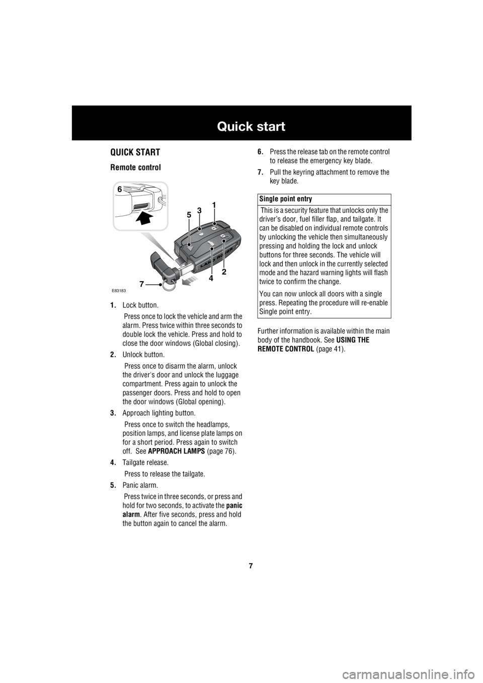
1. Lock button.
Press once to lock the vehicle and arm the
alarm. Press twice within three seconds to
double lock the vehicle. Press and hold to
close the door windows (Global closing).
2. Unlock button.
Press once to disarm the alarm, unlock
the driver's door and unlock the luggage
compartment. Press again to unlock the
passenger doors. Press and hold to open
the door windows (Global opening).
3. Approach lighting button.
Press once to switch the headlamps,
position lamps, and license plate lamps on
for a short period. Press again to switch
off. See APPROACH LAMPS (page 76).
4. Tailgate release.
Press to release the tailgate.
5. Panic alarm.
Press twice in three seconds, or press and
hold for two seconds, to activate the panic
alarm . After five seconds, press and hold
the button again to cancel the alarm. 6.
Press the release tab on the remote control
to release the emergency key blade.
7. Pull the keyring attachment to remove the
key blade.
Further information is available within the main
body of the handbook. See USING THE
REMOTE CONTROL (page 41).
6
31
E83183
2
74
5
Single point entry
This is a security feature that unlocks only the
driver’s door, fuel fille r flap, and tailgate. It
can be disabled on indi vidual remote controls
by unlocking the vehicle then simultaneously
pressing and holding th e lock and unlock
buttons for three sec onds. The vehicle will
lock and then unlock in the currently selected
mode and the hazard wa rning lights will flash
twice to confirm the change.
You can now unlock all doors with a single
press. Repeating the pr ocedure will re-enable
Single point entry.
Page 2728 of 3229
8
Quick start
L
Engine starting
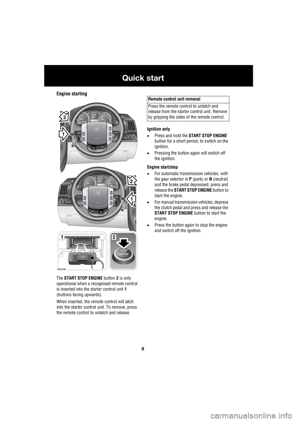
The START STOP ENGINE button 2 is only
operational when a rec ognised remote control
is inserted into the starter control unit 1
(buttons facing upwards).
When inserted, the remo te control will latch
into the starter control unit. To remove, press
the remote control to unlatch and release. Ignition only
• Press and hold the START STOP ENGINE
button for a short period, to switch on the
ignition.
• Pressing the button again will switch off
the ignition.
Engine start/stop
• For automatic transmission vehicles, with
the gear selector in P (park) or N (neutral)
and the brake pedal de pressed, press and
release the START STOP ENGINE button to
start the engine.
• For manual transmission vehicles, depress
the clutch pedal and press and release the
START STOP ENGINE button to start the
engine.
• Press the button again to stop the engine
and switch off the ignition.
1
EXT C23EXT F72EXT C21
EXT C23EXT F72EXT C21
1
1
2
2
E83184
2
Remote control unit removal
Press the remote control to unlatch and
release from the starter control unit. Remove
by gripping the sides of the remote control.
Page 2730 of 3229
10
Quick start
L
Power operated seat adjustment
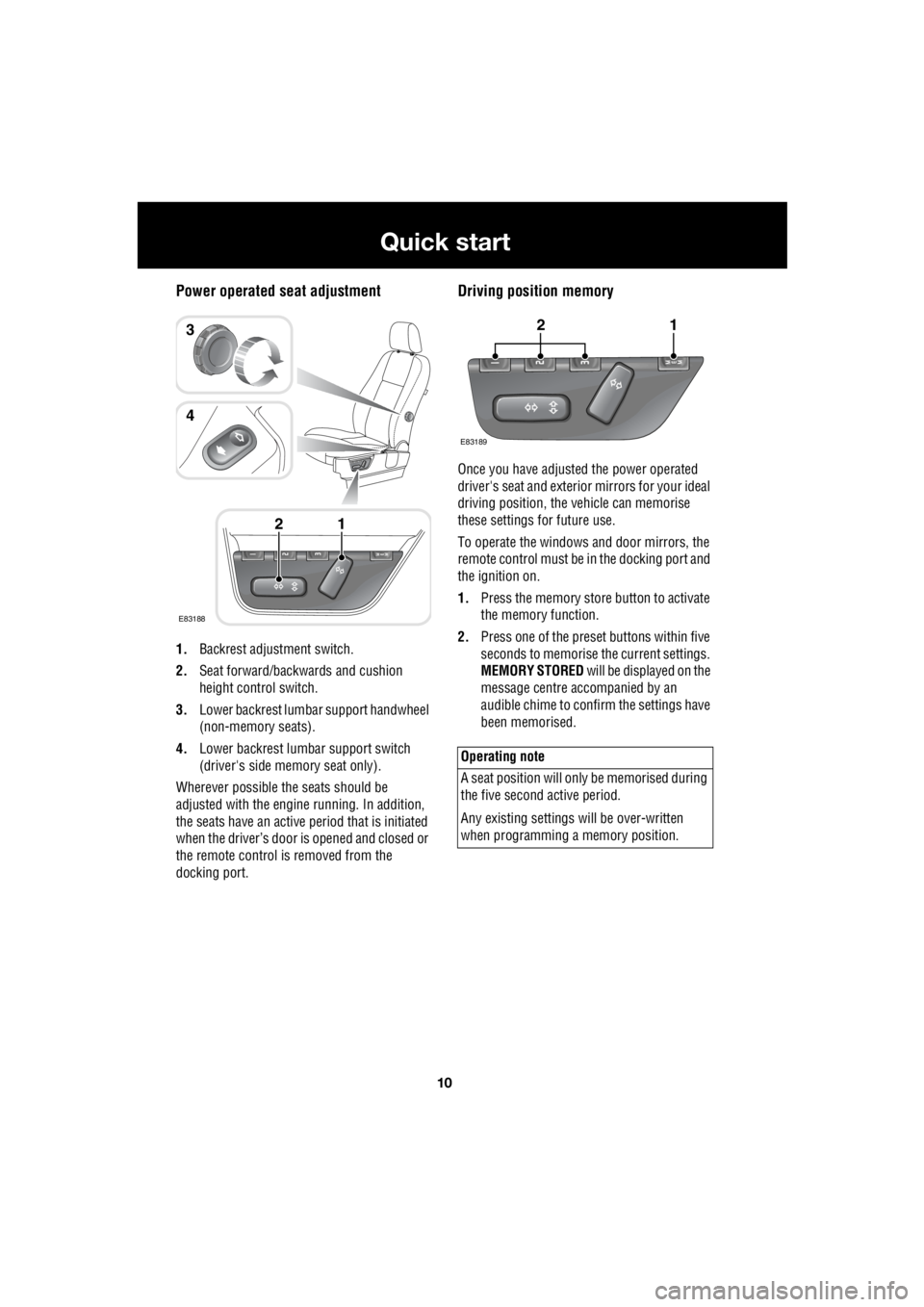
1. Backrest adjustment switch.
2. Seat forward/backwards and cushion
height control switch.
3. Lower backrest lumbar support handwheel
(non-memory seats).
4. Lower backrest lumbar support switch
(driver's side memory seat only).
Wherever possible the seats should be
adjusted with the engine running. In addition,
the seats have an active period that is initiated
when the driver’s door is opened and closed or
the remote control is removed from the
docking port.
Driving position memory
Once you have adjusted the power operated
driver's seat and exterior mirrors for your ideal
driving position, the vehicle can memorise
these settings for future use.
To operate the windows and door mirrors, the
remote control must be in the docking port and
the ignition on.
1. Press the memory store button to activate
the memory function.
2. Press one of the preset buttons within five
seconds to memorise the current settings.
MEMORY STORED will be displayed on the
message centre accompanied by an
audible chime to confirm the settings have
been memorised.
E83188
12
3
4
Operating note
A seat position will onl y be memorised during
the five second active period.
Any existing settings w ill be over-written
when programming a memory position.
E83189
12