2006 LAND ROVER FRELANDER 2 water pump
[x] Cancel search: water pumpPage 1737 of 3229
Publi shed: 26-Jul-2011
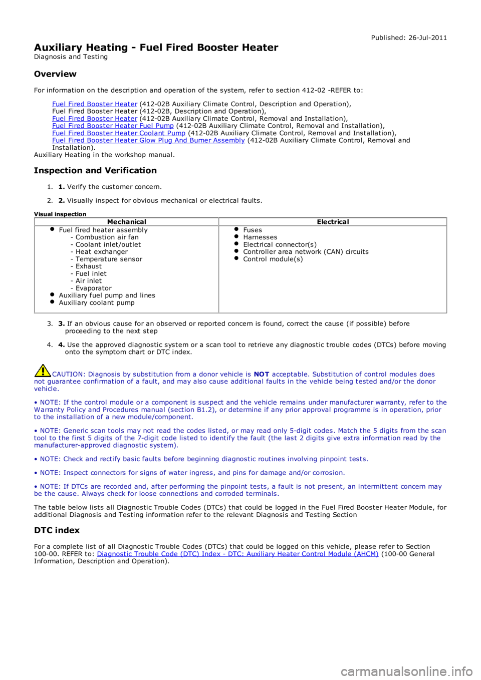
Auxiliary Heating - Fuel Fired Booster Heater
Diagnosi s and Tes ti ng
Overview
For informati on on t he des cri pti on and operati on of the s ys tem, refer t o s ect ion 412-02 -REFER to:
Fuel Fired Boos t er Heat er (412-02B Auxil iary Cli mate Cont rol, Des cri pt ion and Operati on),Fuel Fired Boos t er Heat er (412-02B, Des cript ion and Operat ion),Fuel Fired Boos t er Heat er (412-02B Auxil iary Cli mate Cont rol, Removal and Ins t al lat ion),Fuel Fired Boos t er Heat er Fuel Pump (412-02B Auxili ary Cl imat e Control, Removal and Ins tall ati on),Fuel Fired Boos t er Heat er Cool ant Pump (412-02B Auxil iary Cli mate Cont rol, Removal and Ins t al lat ion),Fuel Fired Boos t er Heat er Glow Pl ug And Burner As sembl y (412-02B Auxi liary Cli mate Cont rol , Removal andIns tal lat ion).Auxi li ary Heat ing i n the works hop manual .
Inspection and Verification
1. Verify t he cus t omer concern.1.
2. Vis ually ins pect for obvious mechani cal or electrical fault s .2.
Visual inspectionMechanicalElectrical
Fuel fired heater as sembl y- Combus ti on air fan- Coolant inl et /out let- Heat exchanger- Temperat ure s ens or- Exhaus t- Fuel inlet- Ai r inlet- EvaporatorAuxili ary fuel pump and li nesAuxili ary coolant pump
Fus esHarness esEl ect ri cal connector(s )Cont roll er area network (CAN) ci rcuit sCont rol module(s)
3. If an obvious cause for an obs erved or report ed concern is found, correct t he caus e (if pos s ible) beforeproceeding t o t he next s t ep3.
4. Us e the approved di agnos ti c s ys t em or a s can t ool t o ret rieve any diagnos t ic t rouble codes (DTCs ) before movingont o t he sympt om chart or DTC i ndex.4.
CAUTION: Di agnos is by s ubs ti tut ion from a donor vehicle is NO T acceptabl e. Subs ti tut ion of cont rol modules doesnot guarant ee confirmat ion of a faul t, and may als o caus e addit ional fault s i n t he vehi cl e being t est ed and/or t he donorvehi cl e.
• NOTE: If the control modul e or a component i s s us pect and the vehicle remains under manufacturer warrant y, refer t o theW arranty Pol icy and Procedures manual (s ect ion B1.2), or determine i f any pri or approval programme is in operat ion, pri ort o the ins tall ati on of a new module/component.
• NOTE: Generic scan t ool s may not read the codes li st ed, or may read only 5-digi t codes . Match t he 5 digi ts from t he s cant ool t o t he fi rs t 5 di gi ts of the 7-digit code li s ted t o i dent ify the fault (the last 2 digi ts gi ve ext ra informati on read by themanufacturer-approved di agnos ti c s ys t em).
• NOTE: Check and recti fy bas ic faul ts before beginni ng diagnos t ic rout ines i nvol vi ng pinpoint t es t s.
• NOTE: Ins pect connect ors for s igns of water ingres s , and pins for damage and/or corros ion.
• NOTE: If DTCs are recorded and, aft er performi ng the pi npoi nt tes ts , a fault is not present , an int ermi tt ent concern maybe t he caus e. Always check for loose connect ions and corroded terminals .
The t abl e below l is t s all Diagnos ti c Trouble Codes (DTCs ) t hat could be logged in the Fuel Fi red Boos ter Heater Module, foraddi ti onal Di agnos is and Tes ti ng informat ion refer t o t he relevant Diagnosi s and Test ing Secti on
DTC index
For a compl ete lis t of all Di agnos ti c Trouble Codes (DTCs) t hat could be logged on this vehicle, pleas e refer to Sect ion100-00. REFER t o: Diagnost ic Troubl e Code (DTC) Index - DTC: Auxi li ary Heater Control Modul e (AHCM) (100-00 GeneralInformat ion, Des cript ion and Operat ion).
Page 1791 of 3229
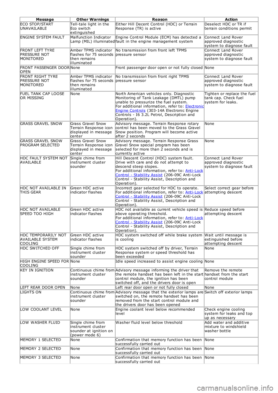
MessageO ther WarningsReasonAction
ECO STOP/STARTUNAVAILABLETel l-tal e li ght in t heEco swi tchext inguis hed
Eit her Hi ll Decent Control (HDC) or TerrainRespons e (TR) i s act iveDes elect HDC or TR i fterrain condit ions permi t
ENGINE SY STEM FAULTMalfunct ion Indi cat orLamp (MIL) il lumi nat edEngi ne Cont rol Module (ECM) has detected afault i n t he engi ne management s ys temConnect Land Roverapproved di agnos ti csys tem t o diagnos e faultFRONT LEFT TY REPRESSURE NOTMONITORED
Amber TPMS indicatorfl ashes for 75 secondsthen remainsil lumi nat ed
No t rans mis s ion from front left TPMSpres sure s ensorConnect Land Roverapproved di agnos ti csys tem t o diagnos e fault
FRONT PASSENGER DOOROPENNoneFront pas s enger door open or not fully cl osedNone
FRONT RIGHT TY REPRESSURE NOTMONITORED
Amber TPMS indicatorfl ashes for 75 secondsthen remainsil lumi nat ed
No t rans mis s ion from front ri ght TPMSpres sure s ensorConnect Land Roverapproved di agnos ti csys tem t o diagnos e fault
FUEL TANK CAP LOOSEOR MISSINGNoneNort h American vehi cl es onl y. Diagnos t icMonit oring of Tank Leakage (DMTL) pumpunabl e to pres surize t he fuel s yst em.For addit ional informati on, refer t o: Elect roni cEngi ne Cont rol s (303-14A Electroni c Engi neCont rol s - I6 3.2L Pet rol, Des cri pt ion andOperati on).
Ti ght en or repl ace t he fueltank cap. Check fuelsys tem for l eaks .
GRASS GRAVEL SNOWGras s Gravel SnowTerrai n Res pons e i condis played in mess agecent er
Advi sory mes s age. Terrain Res pons e rotarycont rol has been moved to the Grass GravelSnow posi ti on. Program will become acti veaft er 2 s econds
None
GRASS GRAVEL SNOWPROGRAM SELECTEDGras s Gravel SnowTerrai n Res pons e i condis played in mess agecent er
Advi sory mes s age. Terrain Res pons e Gras sGravel Snow special program has beens el ect ed for more t han 2 s econds and i scurrent ly acti ve
None
HDC FAULT SY STEM NOTAVAILABLESingle chime fromins trument cl ust ers ounder
Hil l Des cent Cont rol (HDC) sys tem faul t.Dri ve wit h care and do not at tempt t odes cend s teep s lopes .For addit ional informati on, refer t o: Ant i-LockCont rol - St abi li ty As s is t (206-09C Anti -LockCont rol - St abi li ty As s is t , Des cri pti on andOperati on).
Connect Land Roverapproved di agnos ti csys tem t o diagnos e fault
HDC NOT AVAILABLE INTHIS GEARGreen HDC act iveindicator flas hesIncorrect gear s el ect ed for HDC to operate.For addit ional informati on, refer t o: Ant i-LockCont rol - St abi li ty As s is t (206-09C Anti -LockCont rol - St abi li ty As s is t , Des cri pti on andOperati on).
Sel ect correct gear beforeat t empt ing des cent
HDC NOT AVAILABLESPEED TOO HIGHGreen HDC act iveindicator flas hesHDC not avai lable as current vehi cl e s peed isabove operat ing t hres hold.For addit ional informati on, refer t o: Ant i-LockCont rol - St abi li ty As s is t (206-09C Anti -LockCont rol - St abi li ty As s is t , Des cri pti on andOperati on).
Reduce s peed beforeat t empt ing des cent
HDC TEMPORARILY NOTAVAILABLE SY STEMCOOLING
Green HDC act iveindicator flas hesHDC s yst em swi tched off whi le brake s ys t emis cooli ngW ait unt il mes sage i sext inguis hed beforeat t empt ing des cent
HDC SW ITCHED O FFSingle chime fromins trument cl ust ers ounder
HDC s yst em swi tched off by driver, TerrainRespons e s ys t em or s peed thres hold hasbeen exceeded
None
HIGH ENGINE SPEED FORCOOLINGNoneIdl e s peed increased to as s is t engine cool ingNone
KEY IN IGNITIONCont inuous chi me fromins trument cl ust ers ounder
Advi sory mes s age informing the driver thatthe remot e hands et has been left i n t he s tartcont rol module, t he ignit ion has beens wit ched off, and t he dri vers door i s open
Remove t he remotehands et from t he s tartcontrol modul e
LEFT REAR DOOR O PENNoneLeft rear door open or not ful ly cl os edNone
LIGHTS ONCont inuous chi me fromins trument cl ust ers ounder
Advi sory mes s age that t he ext eri or l amps ares wit ched on, t he remot e hands et has beenremoved from the s t art control modul e andthe drivers door has been opened
Swi tch off ext eri or lamps
LOW COOLANT LEVELNoneEngi ne cool ant l evel below recommendedlevelCheck engine cool ingsys tem for l eaks and t opup as neces sary
LOW W ASHER FLUIDSingle chime fromins trument cl ust ers ounder at ignit ion on(power mode 6)
W as her flui d level bel ow t hres hol dAdd water and addi ti vemixt ure t o wi nds hiel dwas her bott le
MEMORY 1 SELECTEDNoneConfirmati on t hat memory funct ion has beens uccess ful ly carried outNone
MEMORY 2 SELECTEDNoneConfirmati on t hat memory funct ion has beens uccess ful ly carried outNone
MEMORY 3 SELECTEDNoneConfirmati on t hat memory funct ion has beens uccess ful ly carried outNone
Page 2886 of 3229
Maintenance
166
L
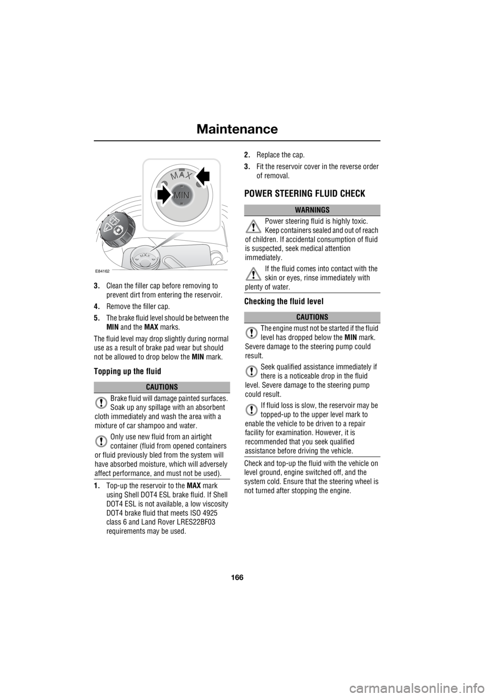
3. Clean the filler cap before removing to
prevent dirt from entering the reservoir.
4. Remove the filler cap.
5. The brake fluid level should be between the
MIN and the MAX marks.
The fluid level may drop slightly during normal
use as a result of brake pad wear but should
not be allowed to drop below the MIN mark.
Topping up the fluid
1.Top-up the reservoir to the MAX mark
using Shell DOT4 ESL brake fluid. If Shell
DOT4 ESL is not availa ble, a low viscosity
DOT4 brake fluid that meets ISO 4925
class 6 and Land Rover LRES22BF03
requirements ma y be used. 2.
Replace the cap.
3. Fit the reservoir cover in the reverse order
of removal.
POWER STEERING FLUID CHECK
Checking the fluid level
Check and top-up the fluid with the vehicle on
level ground, engine switched off, and the
system cold. Ensure that the steering wheel is
not turned after stopping the engine.
CAUTIONS
Brake fluid will damage painted surfaces.
Soak up any spillage with an absorbent
cloth immediately and wash the area with a
mixture of car sh ampoo and water.
Only use new fluid from an airtight
container (fluid from opened containers
or fluid previously bled from the system will
have absorbed moisture, which will adversely
affect performance, and must not be used).
E84162
WARNINGS
Power steering fluid is highly toxic.
Keep containers sealed and out of reach
of children. If accidental consumption of fluid
is suspected, seek medical attention
immediately.
If the fluid comes into contact with the
skin or eyes, rinse immediately with
plenty of water.
CAUTIONS
The engine must not be started if the fluid
level has dropped below the MIN mark.
Severe damage to th e steering pump could
result.
Seek qualified assistance immediately if
there is a noticeable drop in the fluid
level. Severe damage to the steering pump
could result.
If fluid loss is slow, the reservoir may be
topped-up to the uppe r level mark to
enable the vehicle to be driven to a repair
facility for examinatio n. However, it is
recommended that you seek qualified
assistance before driving the vehicle.
Page 2887 of 3229
167
Maintenance
R
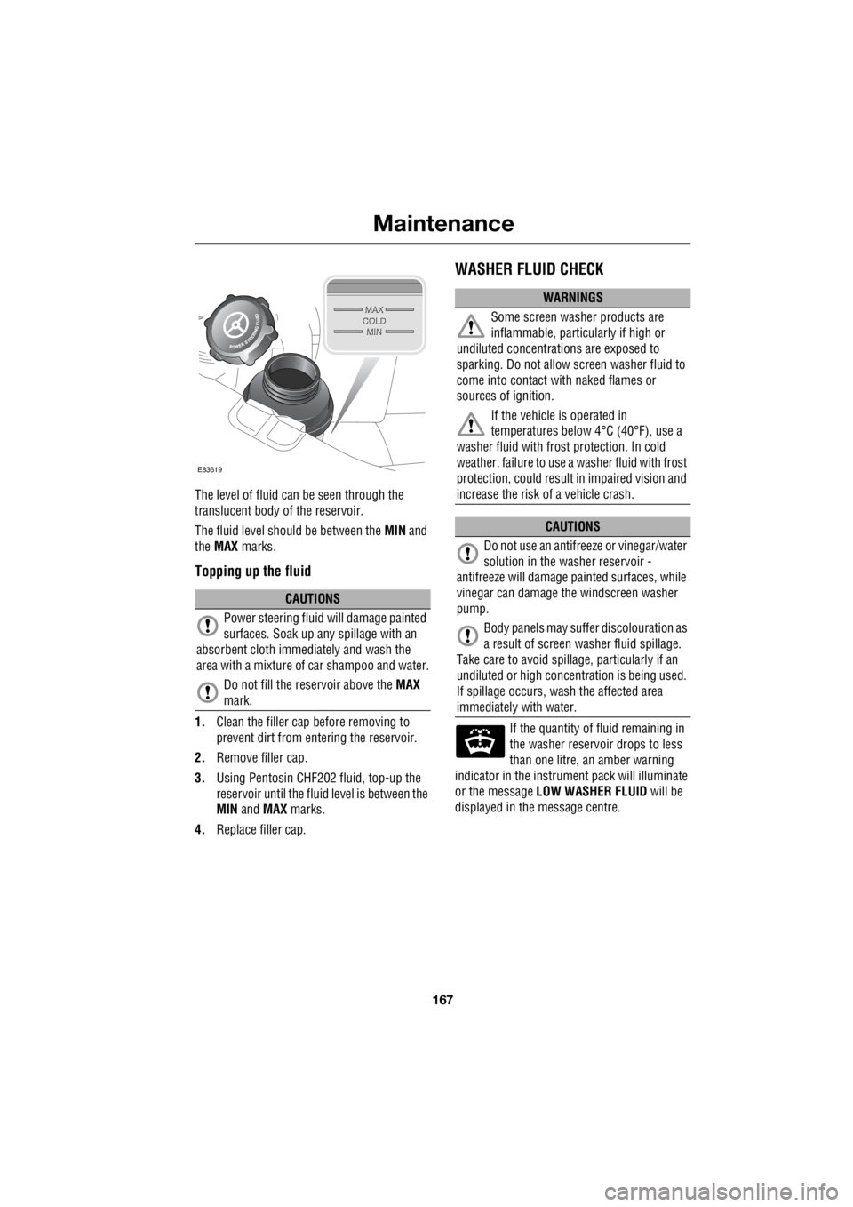
The level of fluid can be seen through the
translucent body of the reservoir.
The fluid level should be between the MIN and
the MAX marks.
Topping up the fluid
1.Clean the filler cap before removing to
prevent dirt from entering the reservoir.
2. Remove filler cap.
3. Using Pentosin CHF202 fluid, top-up the
reservoir until the flui d level is between the
MIN and MAX marks.
4. Replace filler cap.
WASHER FLUID CHECK
If the quantity of fluid remaining in
the washer reservoir drops to less
than one litre, an amber warning
indicator in the instrument pack will illuminate
or the message LOW WASHER FLUID will be
displayed in the message centre.
CAUTIONS
Power steering fluid will damage painted
surfaces. Soak up any spillage with an
absorbent cloth immediately and wash the
area with a mixture of car shampoo and water.
Do not fill the reservoir above the MAX
mark.
E83619
WARNINGS
Some screen washer products are
inflammable, particul arly if high or
undiluted concentrati ons are exposed to
sparking. Do not allow screen washer fluid to
come into contact with naked flames or
sources of ignition.
If the vehicle is operated in
temperatures below 4°C (40°F), use a
washer fluid with frost protection. In cold
weather, failure to use a washer fluid with frost
protection, could result in impaired vision and
increase the risk of a vehicle crash.
CAUTIONS
Do not use an antifree ze or vinegar/water
solution in the washer reservoir -
antifreeze will damage painted surfaces, while
vinegar can damage th e windscreen washer
pump.
Body panels may suff er discolouration as
a result of screen washer fluid spillage.
Take care to avoid spilla ge, particularly if an
undiluted or high concentr ation is being used.
If spillage occurs, wash the affected area
immediately with water.
Page 3024 of 3229
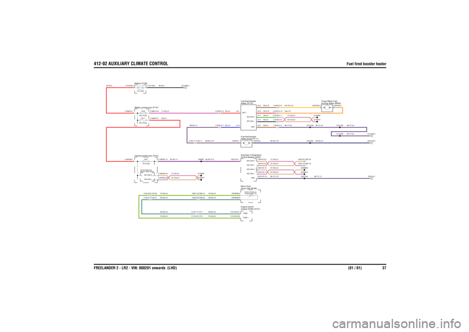
412-02 AUXILIARY CLIMATE CONTROL
Fuel fired booster heater
FREELANDER 2 - LR2 - VIN: 000201 onwards (LHD) (01 / 01) 37
Fuel fired booster heater
YE-GN,0.5GN-BU,0.5GN-BU,0.5YE-GN,0.5
VT-OG,0.5GY-OG,0.5
YE-GN,0.5GN-BU,0.5GN-BU,0.5YE-GN,0.5
RD,6.0VT-RD,2.5BK,35.0
RD,25.0
BN-BU,0.75
BU-RD,1.0
BN-BU,1.0
BU-RD,0.75
RD,2.5BU,0.5
VT-OG,0.5GY-OG,0.5
BK-VT,1.5
BK-VT,0.75VT-OG,0.5GY-OG,0.5
BK-VT,2.5
OG,0.75
BK-BU,2.5
OG-YE,0.75BK-VT,2.5
BK-BU,0.75
VT-OG,0.5GY-OG,0.5
RD,0.75BN,0.75BK,0.5GN,0.5BN,2.5
BK-VT,2.5
BK-VT,6.0
module (ECM) (D131)
Engine control-
temperature (T119)
Sensor-Ambient air-
Driver side (M168)
Mirror-Door-heater pump (H111)
Fuel fired boosterheater (H115)
Fuel fired boosterControl Module (D243)
Automatic Temperature
Central junction-box (P101)
Module (CEM) (D316)
Central ElectronicsC12H-31 C12G-31C12H-36 C12G-36
C11N-6 C11P-6C11N-7 C11P-7C25A-20 C25B-20C25A-19 C25B-19
FE17
60.0 AmpsFS27
10.0 AmpsFE32
20.0 Amps
Battery junction-box (P147)Battery (P100)12.0 Volts
C12H-17 C12G-17
C1HF01C-3C1HF01C-7
C23E-19 C23F-19
burning heater (M202)
Pump-Water-Fuel-
C1HF01C-4C1HF01C-6C1HF01C-10C1HF01C-11C1HF01C-9
C23E-20 C23F-20
C1E104H-E1
TAMB -C1E104H-D2TAMB +
MS CAN LMS CAN H
S1DB07FS1DB06F
C1BP02A-49C1BP02A-50
C5PM26B-6C5PM26B-5
C1D134B-1C1BB07G-1C1BB01A-91
C1BP02G-1C1BB01B-1C1DC02A-1
S2BB27
C1BP02C-74
C2H101D-1C3HF03-1
X1-5X2-1 BATT
G1D108A-1
C2H101D-9
MS CAN LC2H101D-11
MS CAN LC2H101D-10
MS CAN HC2H101D-18
GND
S2D134AS2DB07GS2DB06G
G3D134-1
C3HF03A-1S1D132BS1D132C
C2H101D-8
MS CAN H
C3HF03-2
X1-4
MS CAN LX2-2
GNDX3-3X3-2X1-7
MS CAN H
S4D152C
C3HF03A-2S1DB07FS1DB06F
S1D132A
G1D132A-1G4D151B-1
Page 3131 of 3229
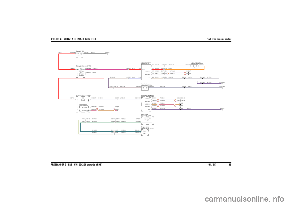
412-02 AUXILIARY CLIMATE CONTROL
Fuel fired booster heater
FREELANDER 2 - LR2 - VIN: 000201 onwards (RHD) (01 / 01) 36
Fuel fired booster heater
YE-GN,0.5GN-BU,0.5GN-BU,0.5YE-GN,0.5
VT-OG,0.5GY-OG,0.5
YE-GN,0.5GN-BU,0.5GN-BU,0.5YE-GN,0.5
RD,6.0VT-RD,2.5BK,35.0
RD,25.0
BN-BU,0.75
BU-RD,1.0
BN-BU,1.0
BU-RD,0.75
RD,2.5BU,0.5
VT-OG,0.5GY-OG,0.5
BK-VT,1.5
BK-VT,0.75VT-OG,0.5GY-OG,0.5
BK-VT,2.5
OG,0.75
BK-BU,2.5
OG-YE,0.75BK-VT,2.5
BK-BU,0.75
VT-OG,0.5GY-OG,0.5
RD,0.75BN,0.75BK,0.5GN,0.5BN,2.5
BK-VT,2.5
BK-VT,6.0
module (ECM) (D131)
Engine control-
temperature (T119)
Sensor-Ambient air-
Driver side (M168)
Mirror-Door-heater pump (H111)
Fuel fired boosterheater (H115)
Fuel fired boosterControl Module (D243)
Automatic Temperature
Central junction-box (P101)
Module (CEM) (D316)
Central ElectronicsC12H-31 C12G-31C12H-36 C12G-36
C11N-6 C11P-6C11N-7 C11P-7C25A-20 C25B-20C25A-19 C25B-19
FE17
60.0 AmpsFS27
10.0 AmpsFE32
20.0 Amps
Battery junction-box (P147)Battery (P100)12.0 Volts
C12H-17 C12G-17
C1HF01C-3C1HF01C-7
C23E-19 C23F-19
burning heater (M202)
Pump-Water-Fuel-
C1HF01C-4C1HF01C-6C1HF01C-10C1HF01C-11C1HF01C-9
C23E-20 C23F-20
C1E104H-E1
TAMB -C1E104H-D2TAMB +
MS CAN LMS CAN H
S1DB07FS1DB06F
C1BP02A-49C1BP02A-50
C5PM26B-6C5PM26B-5
C1D134B-1C1BB07G-1C1BB01A-91
C1BP02G-1C1BB01B-1C1DC02A-1
S2BB27
C1BP02C-74
C2H101D-1C3HF03-1
X1-5X2-1 BATT
G1D108A-1
C2H101D-9
MS CAN LC2H101D-11
MS CAN LC2H101D-10
MS CAN HC2H101D-18
GND
S2D134AS2DB07GS2DB06G
G3D134-1
C3HF03A-1S1D132BS1D132C
C2H101D-8
MS CAN H
C3HF03-2
X1-4
MS CAN LX2-2
GNDX3-3X3-2X1-7
MS CAN H
S4D152C
C3HF03A-2S1DB07FS1DB06F
S1D132A
G1D132A-1G4D151B-1