Page 609 of 3229
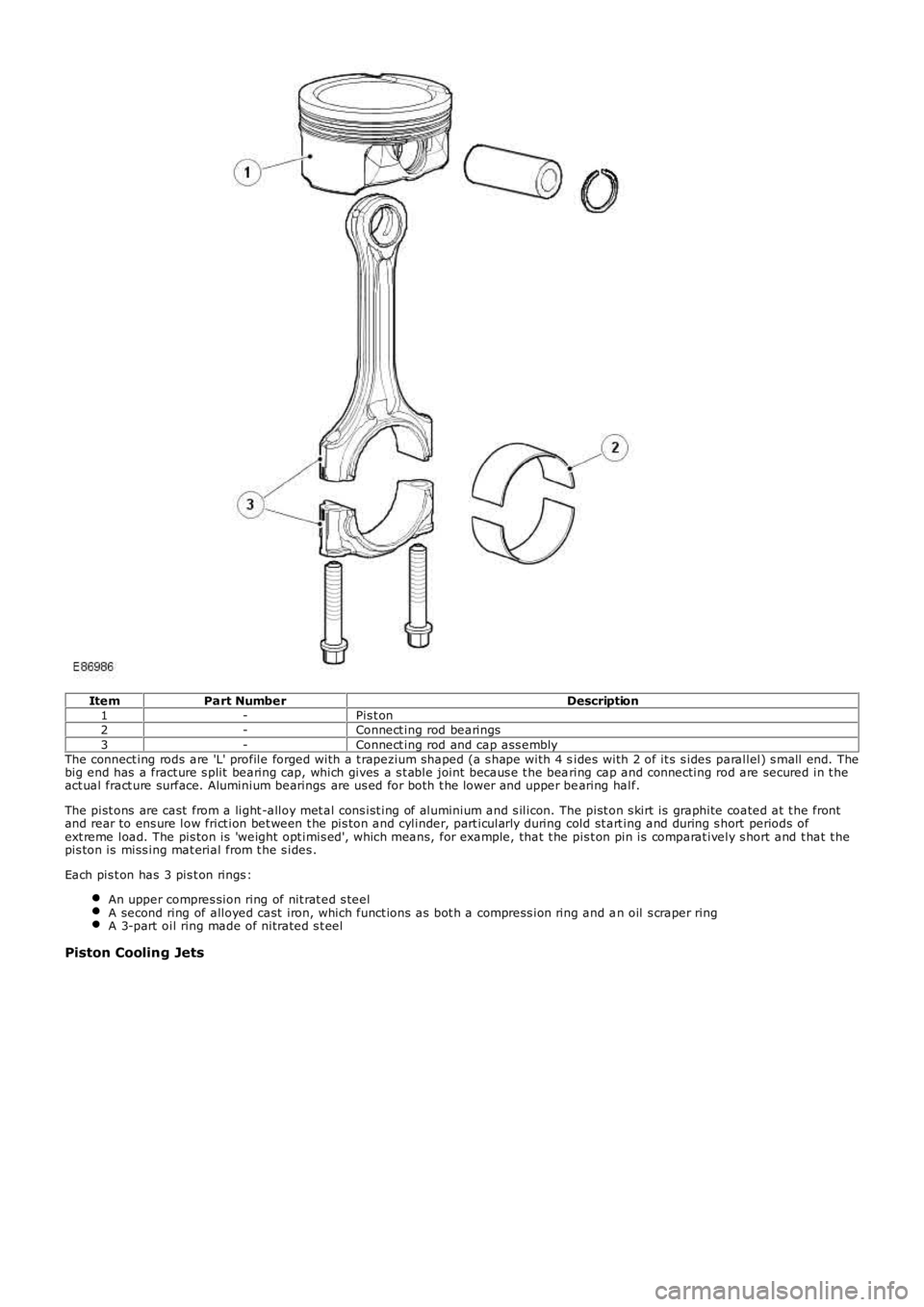
ItemPart NumberDescription1-Pis t on2-Connect ing rod bearings3-Connect ing rod and cap ass emblyThe connect ing rods are 'L' profile forged with a t rapezium shaped (a s hape with 4 sides with 2 of it s s ides parallel) s mall end. Thebig end has a fract ure s plit bearing cap, which gives a s t able joint becaus e t he bearing cap and connecting rod are secured in t heact ual fract ure surface. Aluminium bearings are us ed for both t he lower and upper bearing half.
The pist ons are cast from a light -alloy met al cons ist ing of aluminium and s ilicon. The pist on s kirt is graphite coated at t he frontand rear to ens ure low frict ion bet ween t he pis ton and cylinder, part icularly during cold st art ing and during s hort periods ofext reme load. The pis ton is 'weight opt imis ed', which means, for example, that t he pis t on pin is comparat ively s hort and t hat t hepis ton is miss ing mat erial from t he s ides .
Each pis t on has 3 pis t on rings :
An upper compres sion ring of nit rat ed s teelA second ring of alloyed cast iron, which funct ions as bot h a compress ion ring and an oil s craper ringA 3-part oil ring made of nitrated s t eel
Piston Cooling Jets
Page 620 of 3229
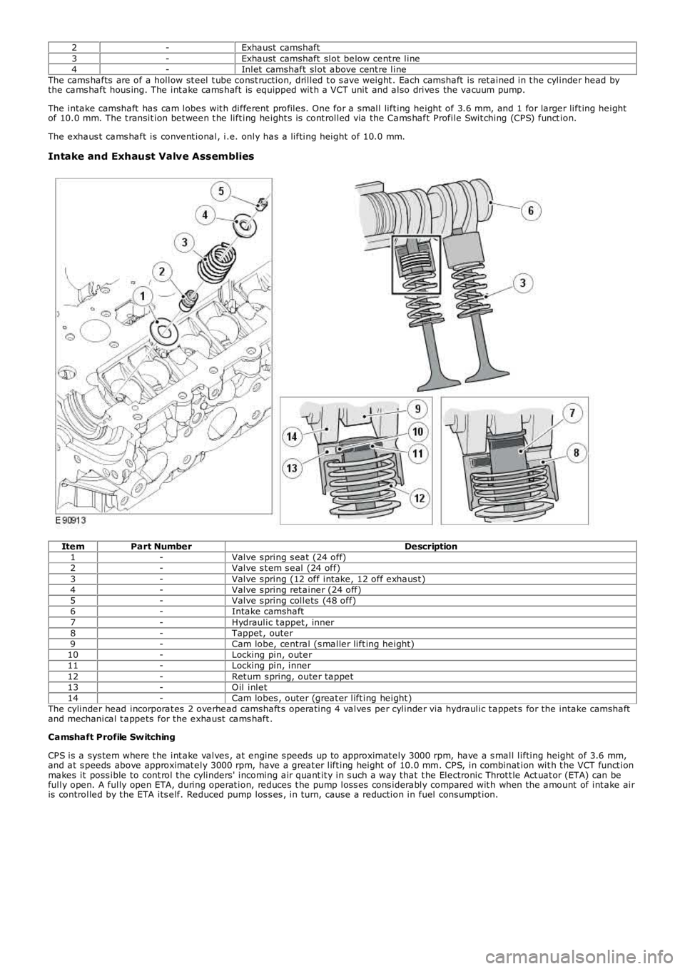
2-Exhaust camshaft3-Exhaust camshaft slot below cent re line4-Inlet camshaft slot above cent re lineThe cams hafts are of a hollow st eel t ube cons t ruction, drilled t o s ave weight . Each camshaft is ret ained in t he cylinder head bythe cams haft hous ing. The int ake cams haft is equipped wit h a VCT unit and also drives the vacuum pump.
The intake camshaft has cam lobes wit h different profiles. One for a small lift ing height of 3.6 mm, and 1 for larger lift ing heightof 10.0 mm. The t ransit ion bet ween t he lift ing height s is cont rolled via the Cams haft Profile Swit ching (CPS) funct ion.
The exhaus t cams haft is convent ional, i.e. only has a lifting height of 10.0 mm.
Intake and Exhaust Valve Assemblies
ItemPart NumberDescription1-Valve s pring s eat (24 off)2-Valve s t em s eal (24 off)3-Valve s pring (12 off int ake, 12 off exhaus t )4-Valve s pring ret ainer (24 off)5-Valve s pring collets (48 off)6-Intake camshaft7-Hydraulic t appet , inner8-Tappet , outer9-Cam lobe, central (s maller lift ing height)10-Locking pin, out er11-Locking pin, inner12-Ret urn s pring, outer tappet13-O il inlet14-Cam lobes , outer (great er lift ing height )The cylinder head incorporat es 2 overhead camshaft s operating 4 valves per cylinder via hydraulic t appet s for the intake camshaftand mechanical t appets for the exhaust cams haft .
Camshaft Profile Sw itching
CPS is a sys tem where t he int ake valves , at engine s peeds up to approximat ely 3000 rpm, have a s mall lifting height of 3.6 mm,and at s peeds above approximat ely 3000 rpm, have a great er lift ing height of 10.0 mm. CPS, in combinat ion wit h t he VCT funct ionmakes it poss ible to cont rol t he cylinders' incoming air quant it y in s uch a way that t he Electronic Throt t le Act uat or (ETA) can befully open. A fully open ETA, during operat ion, reduces t he pump los s es cons iderably compared wit h when the amount of int ake airis controlled by t he ETA its elf. Reduced pump los s es , in turn, cause a reduction in fuel consumpt ion.
Page 632 of 3229
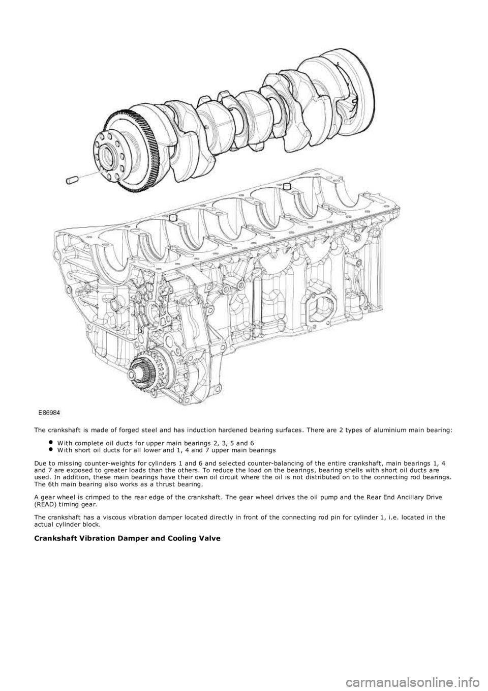
The crankshaft is made of forged s teel and has induction hardened bearing s urfaces . There are 2 types of aluminium main bearing:
W it h complet e oil duct s for upper main bearings 2, 3, 5 and 6W it h short oil ducts for all lower and 1, 4 and 7 upper main bearings
Due t o mis s ing count er-weight s for cylinders 1 and 6 and s elected count er-balancing of the entire crankshaft , main bearings 1, 4and 7 are exposed t o great er loads t han the ot hers. To reduce t he load on the bearings , bearing shells wit h s hort oil duct s areus ed. In addit ion, these main bearings have t heir own oil circuit where t he oil is not dis tribut ed on t o t he connecting rod bearings.The 6t h main bearing als o works as a t hrus t bearing.
A gear wheel is crimped to t he rear edge of the crankshaft . The gear wheel drives t he oil pump and the Rear End Ancillary Drive(READ) t iming gear.
The crankshaft has a vis cous vibration damper locat ed directly in front of t he connecting rod pin for cylinder 1, i.e. located in theact ual cylinder block.
Crankshaft Vibration Damper and Cooling Valve
Page 641 of 3229
The s t art er mot or is located in a recess at t he rear of t he exhaus t s ide of t he oil pan. The motor, rated at 1.4 kW , uses permanentmagnet s ins tead of field windings to provide a low-weight st arter motor; wit h the use of planet ary gears t o deliver a good t orqueto weight ratioFor addit ional information, refer t o: Start ing Syst em (303-06A St art ing Sys t em - I6 3.2L Petrol, Des cript ion and Operat ion)..
CAMSHAFT TIMING COMPONENTS
ItemPart NumberDescription1-Exhaust cams haft2-Intake cams haft3-Vacuum pump4-Cooling pump housing5-Chain guide
Page 768 of 3229
ItemPart NumberDescription
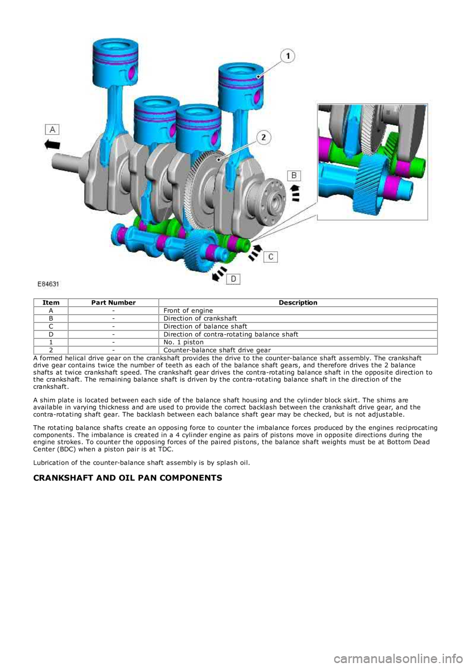
A-Front of engineB-Di recti on of cranks haft
C-Di recti on of bal ance s haft
D-Di recti on of cont ra-rotat ing balance s haft1-No. 1 pi st on
2-Counter-balance s haft dri ve gear
A formed hel ical drive gear on t he cranks haft provi des the drive t o t he count er-bal ance s haft as s embly. The cranks haftdri ve gear contains twi ce the number of teet h as each of the balance s haft gears , and therefore drives t he 2 balances hafts at twi ce cranks haft s peed. The cranks haft gear drives t he cont ra-rot at ing balance s haft i n t he oppos it e direct ion tot he cranks haft . The remai ni ng balance s haft is driven by t he cont ra-rot ati ng bal ance s haft i n t he direct ion of t hecrankshaft .
A s him plat e i s located bet ween each s ide of t he balance s haft hous i ng and the cyli nder bl ock s kirt. The s hims areavai lable in varyi ng thi ckness and are us ed t o provide the correct backl ash bet ween t he cranks haft drive gear, and t hecont ra-rot ati ng shaft gear. The backlas h between each balance s haft gear may be checked, but is not adjus t abl e.
The rot ati ng balance shafts creat e an opposi ng force to counter t he imbal ance forces produced by the engines reci procat ingcomponents . The i mbalance is creat ed in a 4 cyli nder engine as pairs of pis tons move in opposi te direct ions during theengi ne s trokes . To count er the oppos ing forces of the paired pis t ons , t he balance shaft weights must be at Bot tom DeadCenter (BDC) when a pis ton pai r is at TDC.
Lubricati on of the counter-balance s haft as sembl y is by spl as h oi l.
CRANKSHAFT AND OIL PAN COMPONENTS
Page 1039 of 3229
at the rear of the engine. The acces sory dri ve s ys t em overhangs the trans mi ss i on, allowing t he front of the engine to befree of prot rus ions . Thi s unique desi gn cont ri butes t o providi ng a compact and robust engine.
The polyvee access ory dri ve-bel t obtains i ts drive from a s haft , powered by t he crankshaft. The acces s ory drive-belt powerst he:
AC compres s or,engi ne cool ant pump, andpower st eering pump
The engi ne cool ant pump and the power-s t eering pump share a common coupl ing.
Belt t ens i on is maintai ned by an automat ic t ens i on s ys t em whi ch provi des a cons t ant tens ion wi thout bel t s li p.
The generator is direct ly at tached by a coupl ing t o t he rear of t he cranks haft driven s haft. Thi s direct dri ve arrangementimproves the generat or's durabi li ty by prevent ing s ide-loadings, caus ed by the tens ion of a drive belt , act ing on thegenerator's rot or bearing.
In addi ti on t o helping make the engine compact and robust , the novel arrangement of the access ory drive s ys tem als o aidsin reduci ng engi ne weight .
Page 1076 of 3229
Publi s hed: 11-May-2011
Starting System - I6 3.2L Petrol - Starting System
Des cript ion and Operat ion
COMPONENT LOCATION
OVERVIEW
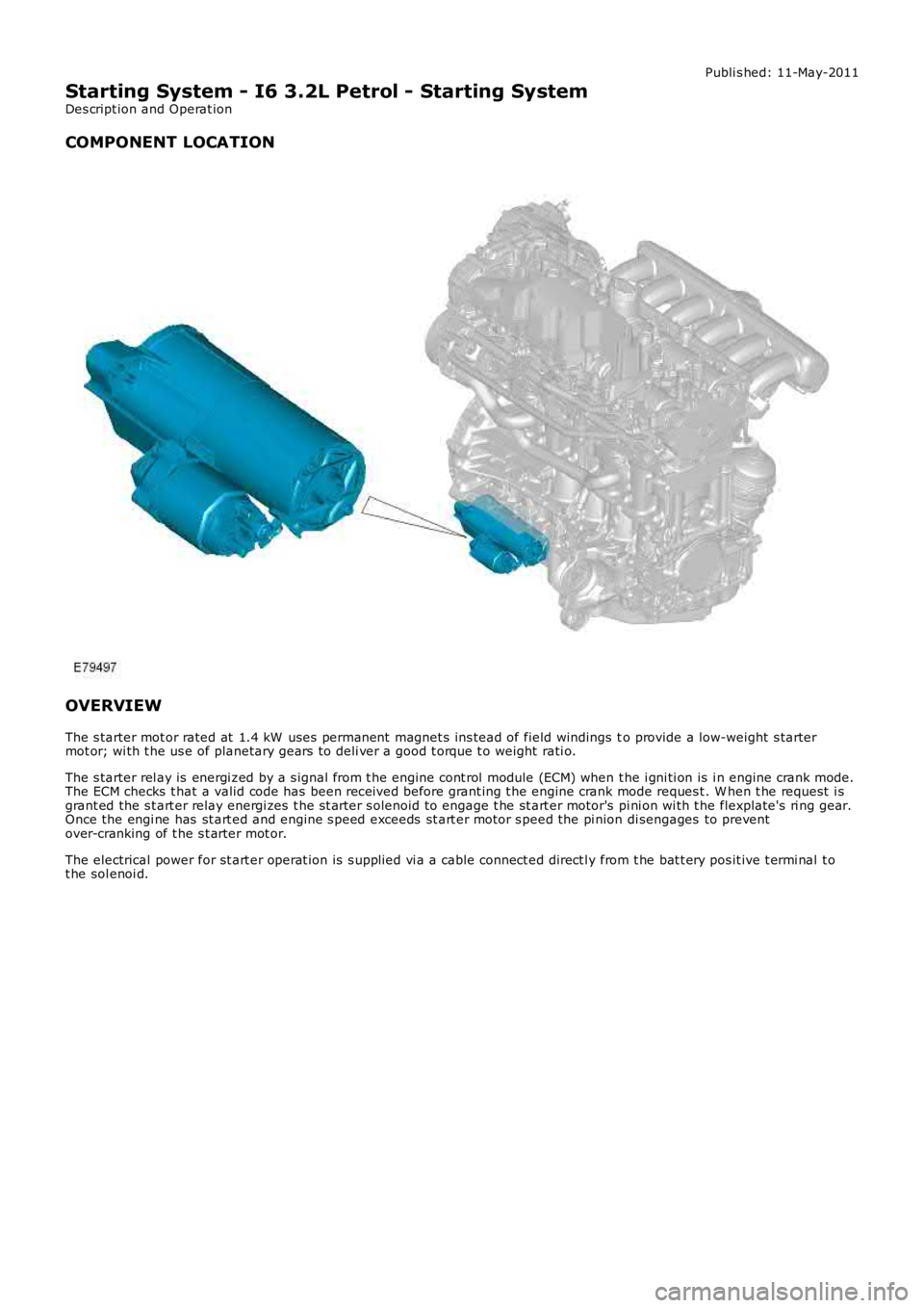
The s tarter mot or rated at 1.4 kW uses permanent magnet s ins tead of field windings to provide a low-weight s tartermot or; wi th t he us e of planetary gears t o deli ver a good t orque t o weight rati o.
The s tarter rel ay is energi zed by a s ignal from t he engine cont rol module (ECM) when t he i gni ti on is i n engine crank mode.The ECM checks t hat a valid code has been received before grant ing t he engine crank mode reques t . W hen t he request i sgrant ed the s t art er relay energi zes t he s t arter s olenoid to engage t he st art er motor's pi ni on wi th t he flexplate's ri ng gear.Once the engi ne has st art ed and engine s peed exceeds st art er motor s peed the pi nion di sengages to preventover-cranking of t he s t arter mot or.
The electrical power for st art er operat ion is s upplied vi a a cable connect ed direct ly from t he bat t ery pos it ive t ermi nal t ot he sol enoi d.
Page 1391 of 3229
Publi s hed: 11-May-2011
Manual Transmission/Transaxle and Clutch - General Information - Manual
Transmission and Clutch
Des cript ion and Operat ion
COMPONENT LOCATION
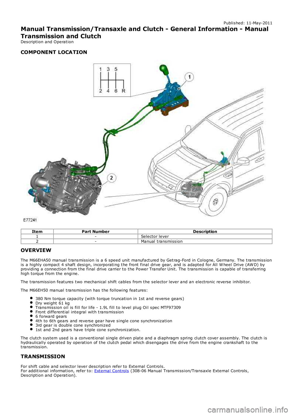
ItemPart NumberDescription1-Selector lever
2-Manual t rans mi ss ion
OVERVIEW
The M66EHA50 manual t rans mis s ion i s a 6 speed unit manufact ured by Get rag-Ford in Col ogne, Germany. The t rans mis s ionis a highly compact 4 s haft desi gn, incorporati ng t he front final dri ve gear, and is adapted for All W heel Dri ve (AW D) byprovidi ng a connecti on from t he final drive carrier t o t he Power Transfer Uni t. The t rans mi ss i on is capabl e of t ransferringhigh t orque from the engi ne.
The t ransmis s ion feat ures t wo mechanical s hift cabl es from t he s elector l ever and an electronic reverse inhibit or.
The M66EH50 manual t rans mis s ion has t he fol lowi ng feat ures:
380 Nm torque capaci ty (wi th torque truncati on in 1st and revers e gears )Dry weight 61 kgTrans mis s ion oi l is fil l for li fe - 1.9L fill t o l evel plug Oi l s pec MTF97309Front different ial int egral wit h t rans mis s ion6 forward gears4th to 6t h gears and revers e gear have s i ngl e cone synchronizati on3rd gear i s doubl e cone synchronized1s t and 2nd gears have triple cone s ynchroni zat ion.
The clutch s ys tem used is a convent ional s ingle driven plat e and a di aphragm s pri ng cl utch cover as s embly. The cl utch i shydraulicall y operated by operat ion of t he clut ch pedal which di sengages the drive from the engine cranks haft t o t het ransmis s ion.
TRANSMISSION
For shi ft cabl e and s elector l ever descripti on refer to Ext ernal Cont rol s.For addit ional informat ion, refer t o: Ext ernal Control s (308-06 Manual Trans mi ss i on/Trans axl e External Controls ,Des cript ion and Operat ion).