Page 2439 of 3229
Tie the horns asi de. T orque:
25 Nm 6.
7. W ARNING: Thi s s tep requi res t he aid of
another technician.
T orque: 48 Nm 7.
Installation To i nst all , revers e t he removal procedure.
1.
Page 2484 of 3229

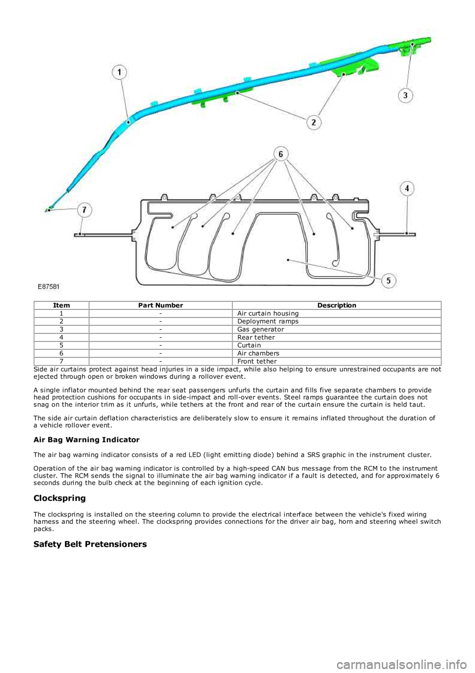
ItemPart NumberDescription
1-Air curt ai n housi ng2-Depl oyment ramps
3-Gas generat or
4-Rear t ether5-Curtai n
6-Air chambers
7-Front tet herSide ai r curtains protect agai nst head i njuri es in a s ide i mpact , whil e als o helpi ng to ens ure unres trai ned occupant s are notejected through open or broken wi ndows during a roll over event .
A s i ngl e inflat or mount ed behi nd t he rear s eat pas s engers unfurl s the curtain and fills fi ve separat e chambers t o providehead prot ect ion cushi ons for occupant s i n s ide-i mpact and roll -over event s. St eel ramps guarantee t he curt ain does nots nag on the interior t ri m as i t unfurl s , whi le tet hers at t he front and rear of t he curt ain ens ure t he curt ain i s held t aut.
The s ide ai r curtain deflat ion characteris ti cs are deli beratel y s low t o ens ure i t remai ns inflated throughout the durat ion ofa vehicle roll over event .
Air Bag Warning Indicator
The air bag warni ng indi cat or cons is ts of a red LED (li ght emit ti ng diode) behi nd a SRS graphic in t he i ns t rument clus ter.
Operat ion of t he air bag warni ng indicator i s cont rol led by a hi gh-s peed CAN bus mess age from t he RCM t o t he ins t rumentclus ter. The RCM s ends t he s ignal to il luminat e t he air bag warni ng indicator i f a faul t is det ect ed, and for approxi matel y 6s econds duri ng the bul b check at t he begi nni ng of each i gnit ion cycl e.
Clockspring
The clocks pri ng is ins tall ed on t he s teeri ng column t o provi de the el ect ri cal i nt erface bet ween t he vehi cl e's fixed wiringharnes s and the st eering wheel . The cl ocks pring provides connecti ons for the driver air bag, horn and s teering wheel swit chpacks .
Safety Belt Pretensioners
Page 2738 of 3229
18
Quick start
L
1. Exterior lamps master switch
2. Direction indicators/headlam ps/trip computer switch
3. Cruise control switches
4. Instrument pack
5. Audio/telephone switches
6. Washer/wiper switch
7. Start stop engine button
8. Master unlock switch
9. Hazard warning switch
10. Master lock switch
11. Audio unit
12. Heater/air conditioning controls
13. Dynamic Stability Control (DSC) switch
14. Gear selector
15. Touch screen
16. Parking brake
17. Terrain Response control switch
18. Hill Descent Control (HDC) switch
19. Starter control unit
20. Steering column adjustment lever
21. Horn switches
22. Facia illumination dimmer control
Page 2763 of 3229
43
Keys and remote controls
R
Tailgate
Press briefly to release the tailgate.
Emergency alarm
Press and hold for three seconds, or
press twice within three seconds, to
activate the horn and the hazard
lamps.
Once active for more than five seconds the
alarm can be cancelled by pressing the button
and holding for three seconds, or pressing
twice within three seconds.
Note: The horn and hazard lamps will switch
off automatically after two minutes and forty
five seconds.
Remote battery
The remote control batteries are recharged
when the remote is docked and the engine is
running. For this reas on it is recommended
that each remote is used periodically. This will
ensure that the batteries are kept charged and
ready for use.
Page 2764 of 3229

Locks
44
L
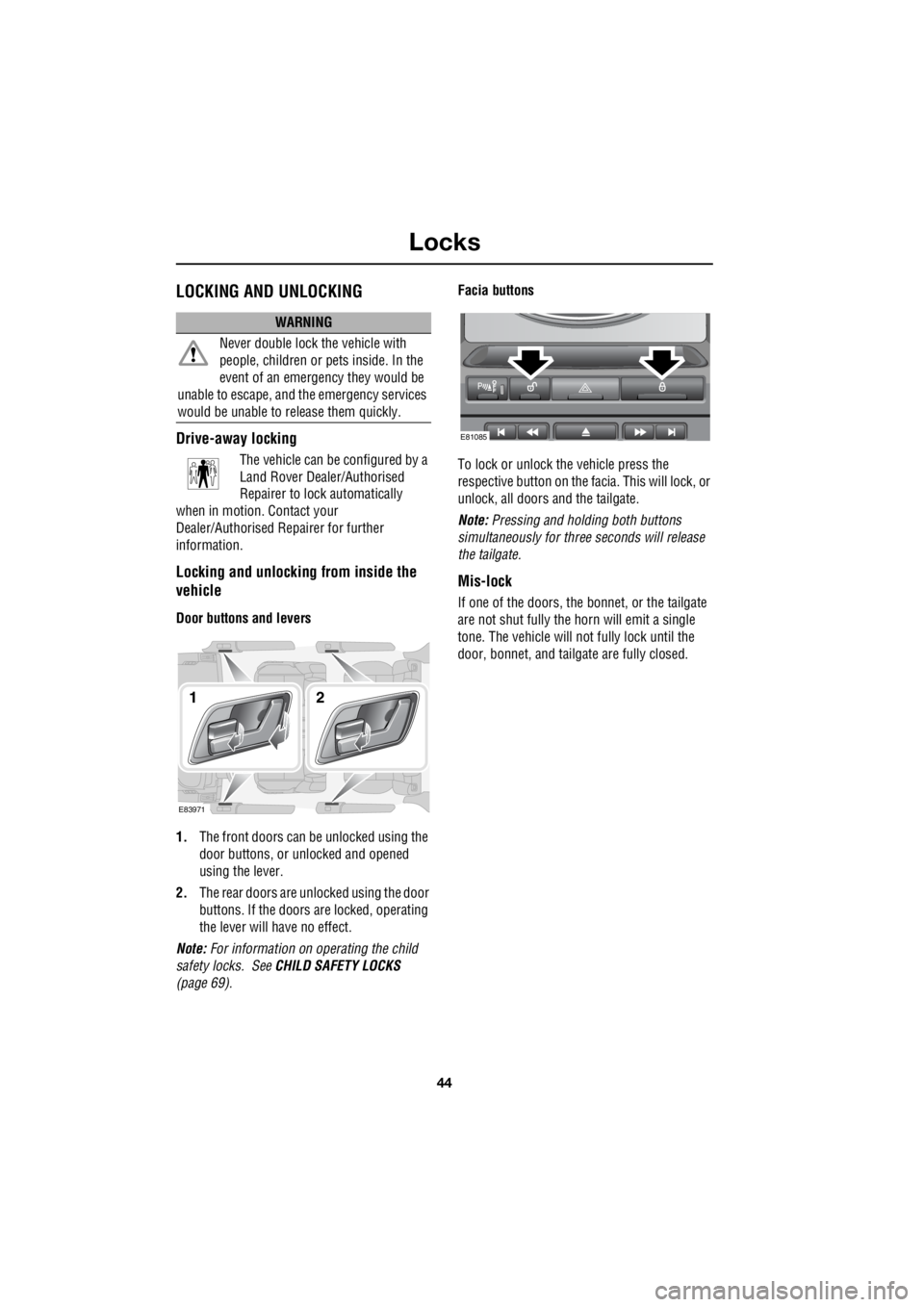
LocksLOCKING AND UNLOCKING
Drive-away locking
The vehicle can be configured by a
Land Rover Dealer/Authorised
Repairer to lock automatically
when in motion. Contact your
Dealer/Authorised Re pairer for further
information.
Locking and unlocking from inside the
vehicle
Door buttons and levers
1. The front doors can be unlocked using the
door buttons, or unlocked and opened
using the lever.
2. The rear doors are unlocked using the door
buttons. If the doors are locked, operating
the lever will have no effect.
Note: For information on operating the child
safety locks. See CHILD SAFETY LOCKS
(page 69). Facia buttons
To lock or unlock the vehicle press the
respective button on the fa cia. This will lock, or
unlock, all doors and the tailgate.
Note: Pressing and holding both buttons
simultaneously for thre e seconds will release
the tailgate.
Mis-lock
If one of the doors, the bon net, or the tailgate
are not shut fully the horn will emit a single
tone. The vehicle will not fully lock until the
door, bonnet, and tailga te are fully closed.
WARNING
Never double lock the vehicle with
people, children or pe ts inside. In the
event of an emergency they would be
unable to escape, and th e emergency services
would be unable to release them quickly.
E83971
12
E81085
Page 2878 of 3229

Maintenance
158
L
One or both types of serv ice interval (distance
and time) may be displayed. For example, if an
engine oil service is du e based on mileage, and
a brake fluid change is due based on time, both
distance and time c ountdowns will display.
Service Portfolio
The Service Portfolio book includes a Service
Record section, which enables a record to be
kept of all the servicing and inspections that are
carried out on the vehicle. This section of the
book also has an area for brake fluid changes
to be recorded.
Ensure your service provider signs and stamps
the book after each se rvice and inspection.
Owner Maintenance
In addition to the routine maintenance, a
number of simple checks must be carried out
more frequently. Advice is given on the pages
that follow.
Daily checks
• Operation of lamps, horn, direction
indicators, wipers, washers and warning
indicators.
• Operation of seat belts and brakes.
• Look for fluid deposits underneath the
vehicle that might indicate a leak.
Weekly checks
• Engine oil level. See ENGINE OIL CHECK
(page 162).
• Engine coolant check. See ENGINE
COOLANT CHECK (page 163).
• Brake/clutch fluid level. See BRAKE AND
CLUTCH FLUID CHECK (page 165). •
Power steering fluid level. See POWER
STEERING FLUID CHECK (page 166).
• Screen washer fluid level. See WASHER
FLUID CHECK (page 167).
• Tyre pressure s and condition.
• Operate air conditioning.
Note: The engine oil leve l should be checked
more frequently if the vehicle is driven for
prolonged periods at high speeds.
Driving in arduous conditions
When a vehicle is operated in extremely
arduous conditions, more frequent attention
must be paid to servicing requirements.
For example, if your vehicle experiences deep
wading conditions, even daily servicing could
be necessary to ensure the continued safe and
reliable operation of the vehicle.
Arduous driving conditions include:
• Driving in dusty and/or sandy conditions.
• Driving on rough and/or muddy roads
and/or wading.
• Driving in extremely hot conditions.
• Towing a trailer or driving in mountainous
conditions.
Contact a Land Rover Dealer/Authorised
Repairer for advice.
Emission control
Your vehicle is fitted with various items of
emission and evaporative control equipment,
designed to meet sp ecific territorial
requirements. You should be aware that
unauthorised replacemen t, modification or
tampering with this equipment by an owner or
repair shop, may be unlawful and subject to
legal penalties.
CAUTION
Any significant or sudden drop in fluid
levels, or uneven tyre wear, should be
reported to a qualified technician without
delay.
Page 2918 of 3229
Fuses
198
L
F24 30 pink Headlamp washers
F25 30 pink ABS
F26 40 green ABS
F27 - - -
F28 40 green Heater blower
F29 - - -
F30 - - -
F31 15 blue Horns
F32 20 yellow Diesel auxiliary heater
F33 5 tan Relays
F34 40 green Heated windscreen(LH)
F35 40 green Heated windscreen (RH)
F36 - - -
F37 10 red Heated washer jets
F38 10 red AFS (RH lamp motors)
F39 10 red Climate control
F40 - - -
F41 20 yellow Passenger compartment fuse box supply
F42 15 blue Engine management
F43 5 tan Headlamp levelling control - AFS
F44 10 red AFS (LH lamp motors)
F45 15 blue Cigar lighter
Fuse number Rating (Amps) Fuse colour Circuits protected
Page 3003 of 3229

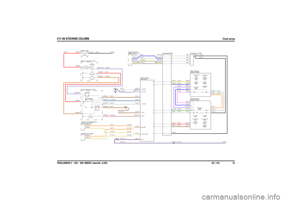
211-04 STEERING COLUMN
Clock spring
FREELANDER 2 - LR2 - VIN: 000201 onwards (LHD) (01 / 01) 15
211-04 STEERING COLUMNClock spring
BK-VT,0.75BN,0.75
BU-GN,0.35WH-RD,0.5WH,0.35BN,0.5
WH,0.5WH-BU,0.5
YE-GN,0.5VT-BN,0.5
BK-VT,1.0
BU,0.5WH,0.5
YE-RD,6.0
OG,0.5 (LO-LINE)OG,0.5 (HI-LINE)GY-YE,0.5 (HI-LINE)GY-YE,0.5 (LO-LINE)
BU-WH,0.5RD,6.0
RD,25.0
BN,0.75
BK,35.0
BK,0.35BK,0.35
BK-VT,1.5WH,0.35RD,0.35BN,0.35VT,0.35BU,0.35PK,0.35GN,0.35BU,0.35YE,0.35
OG,0.35GY,0.35
Module (RCM) (D171)
Restraints Control
Central junction-box (P101)
FS7
7.5 Amps
Audio head unit (D282)control module (D371)
Information and entertainment
FE18
60.0 Amps
FE31
15.0 Amps
Horn (R133) Relay-
Battery junction-box (P147)
Module (CEM) (D316)
Central ElectronicsFET-HORN
FET-IP SUPPLY
FE17
60.0 Amps
Battery (P100)12.0 Volts
wheel (D407)
Module-Steering
wheel-RH (D257)
Module-Steering-
Clock spring (S227)
gap - (Y267) Time-Suspend (Y265)Set - (Y264)
gap + (Y266) Time-Resume (Y202)Set + (Y263)
talk (Y276)Push to-Down (Y280) Channel-Volume + (Y277)
wheel-LH (D256)
Module-Steering-
LH (S341)
Switch-Horn-
RH (S340)
Switch-Horn-
Up (Y279) Channel-Send (Y281) Phone-Volume - (Y278)
Air bag-Driver (U106)
End (Y282)Phone-Mode (Y283)
C2LS41-1
GNDC2LS41-3 AUDIO SW O/PC2LS41-8ILLUMC2LS41-4C2LS41-9 LIN (SJB)C2LS41-10 BATTC2LS41-2
SWS GNDC2LS41-6 HS CAN LC2LS41-7HS CAN HC2LS41-5
C1BP02G-2
C1BP02C-70
C2ME03A-18C2ME03A-7C2ME05A-7C2ME05A-8
S2D134B
C1BP02A-46C1BP02G-1C1BB01B-1C1DC02A-1
C1BP02C-54C1BP02C-10C1BP02C-51C1BP02C-13
BATT A
C1BB03H-1C1BB01A-69C1BB07G-1
S2DB04JS2DB05J
S2LN17
C1D134B-1
G1D108A-1
C2R114C-1C2R114C-3C2R114C-4C2R114C-2
C1254-3S2D134A
C2147-10C2147-9C2147-3
C1254-1C1254-4C1254-7
G3D134-1
C2147-5
C2283-7C2147-4C2147-1C2147-2C2147-8C2283-6
C1254-6
C2283-1C2283-2C2283-3
C1254-2C1254-5
C2R115D-1C2R115D-7C2R115D-8C2R115D-2
C68C-2C68C-1C68-2C68-1
C2636-1
C2147-7C2147-6C2283-4C2283-5