Page 297 of 656

ENG
4 - 21
ARBRES A CAMES
NOCKENWELLE
ALBERI A CAMME
AUSBAU
Nockenwelle
1. Demontieren:
l
Schwungrad-Abdeckschrau-
be
1
l
Rotorzapfen-Abdeckschrau-
be
2
2. Ausrichten:
l
Oberer-Totpunkt-Markie-
rung
(mit Ausrichtungsmarke)
Arbeitsschritte
l
Kurbelwelle mit einem Schrau-
benschlüssel gegen den Uhr-
zeigersinn drehen.
HINWEIS:
Durch Drücken des Dekompressi-
onshebels läßt sich die Kurbel-
welle leichter drehen.
l
Oberer-Totpunkt-Markierung
a
am Rotor mit der Markierung
b
am Kurbelgehäusedeckel aus-
richten, wenn der Kolben im
oberen Totpunkt (OT) steht.
HINWEIS:
Der Kolben steht im oberen Tot-
punkt, wenn die Markierung
c
an
der AuslaßNockenwelle und
d
an
der Einlaß-Nokkenwelle laut Ab-
bildung mit der Zylinderkopfkante
fluchtet.
3. Demontieren:
l
Steuerkettenspanner-Ab-
deckschraube
1
l
Steuerkettenspanner
2
l
Dichtung
4. Demontieren:
l
Schraube (Nockenwellen-
Lagerdeckel)
1
l
Nockenwellen-Lagerdeckel
2
l
Clip
HINWEIS:
Die Schrauben der Nockenwellen-
Lagerdekkel kreuzweise von außen
nach innen herausschrauben.
ACHTUNG:
Die Schrauben der Nockenwellen-
Lagerdeckel müssen gleichmäßig
herausgeschraubt werden, um Be-
schädigung an Zylinderkopf, Nok-
kenwellen und Lagerdeckeln zu
vermeiden.
POINTS DE DEPOSE
Arbre à cames
1. Déposer:
l
Bouchon de distribution
1
l
Bouchon droit
2
2. Aligner:
l
Repère de PMH
Avec repère d’alignement.
Etapes de la vérification:
l
Tourner le vilebrequin à l’aide
d’une clé dans le sens inverse des
aiguilles d’une montre.
N.B.:
Actionner le levier de décompres-
sion a fin de faciliter la rotation du
rilebrequin.
l
Aligner le repère de PMH
a
sur le
rotor le repère d’alignement
b
sur
le couvercle du carter quand le pis-
ton se trouve au Point Mort Haut
(PMH) sur la courge de compres-
sion.
N.B.:
Les pistons sont au PMH lorsque le
repère d’alignement
c
de l’arbre à
cames d’échappement et le repère
d’alignement
d
de l’arbr à cames
d’admission s’alignent sur la surface
de la culasse, comme illustré.
3. Déposer:
l
Boulon capuchon du tendeur
de la chaîne de distribution
1
l
Tendeur de la chaîne de distri-
bution
2
l
Joint
4. Déposer:
l
Boulon (chapeaux d’arbre à
cames)
1
l
Chapeaux d’arbre à cames
2
l
Clip
N.B.:
Enlever les boulons de chapeaux d’arbre
à cames en suivant un ordre entrecroisé
et en commençant par l’intérieur.
ATTENTION:
Les boulons (chapeaux d’arbre à
cames) doivent être enlevés uniformé-
ment pour éviter d’abîmer la culasse,
l’arbre à cames ou les chapeaux
d’arbre à cames.PUNTI DI RIMOZIONE
Albero a camme
1. Rimuovere:
l
Vite di accesso al riferimento
per fasatura
1
l
Vite di accesso estremità
albero motore
2
2. Allineare:
l
Riferimento PMS
Al riferimento di allineamento.
Fasi di controllo:
l
Ruotare l’albero motore in senso
antiorario con una chiave.
NOTA:
Schiacciando la leva di decompres-
sione la rotazione dell’albero motore
è agevole.
l
Allineare il riferimento PMS
a
sul
rotore al riferimento
b
sul coper-
chio del carter quando il pistone si
trova nel PMS nella fase di com-
pressione.
NOTA:
Per accertarsi che il pistone sia al
punto morto superiore, la punzona-
tura
c
sull’albero a camme di sca-
rico e la punzonatura
d
sull’albero a
camme di ammissione devono essere
allineate alla superficie della testata
del cilindro, come illustrato nella
figura.
3. Rimuovere:
l
Vite senza dado del tenditore
della catena di distribuzione
1
l
Tenditore della catena di distri-
buzione
2
l
Guarnizione
4. Rimuovere:
l
Bullone (cappello albero a
camme)
1
l
Cappello albero a camme
2
l
Fermaglio a graffa
NOTA:
Rimuovere i bulloni (cappello albero a
camme) in maniera incrociata, operando
dall’esterno verso l’interno.
ATTENZIONE:
I bulloni (cappello dell’albero a
camme) devono essere rimossi in
maniera uniforme per evitare danni
alla testata del cilindro, agli alberi a
camme e ai cappelli degli alberi a
camme.
Page 298 of 656
4 - 22
ENGCAMSHAFTS
5. Remove:
lExhaust camshaft 1
lIntake camshaft 2
NOTE:
Attach a wire 3 to the timing chain to prevent
it from falling into the crankcase.
INSPECTION
Camshaft
1. Inspect:
lCam lobe
Pitting/scratches/blue discoloration ®
Replace.
2. Measure:
lCam lobe length a and b
Out of specification ® Replace.
Cam lobes length:
Intake:
a30.296 ~ 30.346 mm
(1.1923 ~ 1.1947 in)
: 30.196 mm
(1.1888 in)
b22.45 ~ 22.55 mm
(0.8839 ~ 0.8878 in)
: 22.35 mm
(0.8799 in)
Exhaust:
a30.399 ~ 30.499 mm
(1.1968 ~ 1.2007 in)
: 30.299 mm
(1.1929 in)
b22.45 ~ 22.55 mm
(0.8839 ~ 0.8878 in)
: 22.35 mm
(0.8799 in)
3. Measure:
lRunout (camshaft)
Out of specification ® Replace.
Runout (camshaft):
Less than 0.03 mm (0.0012 in)
Page 299 of 656

ENG
4 - 22
ARBRES A CAMES
NOCKENWELLE
ALBERI A CAMME
5. Demontieren:
l
Auslaß-Nockenwelle
1
l
Einlaß-Nockenwelle
2
HINWEIS:
Die Steuerkette mit einem Draht
3
sichern, damit sie nicht herabfällt.
PRÜFUNG
Nockenwelle
1. Kontrollieren:
lNocke
Pitting/Riefen/Blaufärbung
® Erneuern.
2. Messen:
lNockenabmessungen a
und b
Unvorschriftsmäßig ®
Erneuern.
Nockenabmessungen
(Verschleißgrenze)
Einlaß
a30,296–30,346 mm
30,196 mm
b22,45–22,55 mm
22,35 mm
Auslaß:
a30,399–30,499 mm
30,299 mm
b22,45–22,55 mm
22,35 mm
3. Messen:
lNockenwellenschlag
Unvorschriftsmäßig ®
Erneuern.
Max. zul. Nockenwellen-
schlag
unter 0,03 mm
5. Déposer:
lArbre à cames d’échappement
1
lArbre à cames d’admission 2
N.B.:
Attacher un fil 3 à la chaîne de distribu-
tion pour éviter qu’elle tombe dans le
carter moteur.
CONTROLE
Arbre à cames
1. Contrôler:
lCame
Piqûres/rayures/décoloration
bleue ® Remplacer.
2. Mesurer:
lLongueur de came a et b
Hors spécifications ® Rempla-
cer.
Limite de longueur de
came:
Admission:
a30,296 à 30,346 mm
(1,1923 à 1,1947 in)
:30,196 mm
(1,1888 in)
b22,45 à 22,55 mm
(0,8839 à 0,8878 in)
:22,35 mm
(0,8799 in)
Echappement:
a30,399 à 30,499 mm
(1,1968 à 1,2007 in)
:30,299 mm
(1,1929 in)
b22,45 à 22,55 mm
(0,8839 à 0,8878 in)
:22,35 mm
(0,8799 in)
3. Mesurer:
lFaux-rond (arbre à cames)
Hors spécifications ® Rempla-
cer.
Faux-rond (arbre à
cames):
Moins de 0,03 mm
(0,0012 in)
5. Rimuovere:
lAlbero a camme di scarico 1
lAlbero a camme di aspirazione
2
NOTA:
Collegare un cavo 3 alla catena di
distribuzione per impedire che cada nel
carter.
ISPEZIONE
Albero a camme
1. Ispezionare:
lLobo di camma
Corrosione/graffi/sbiadimento
blu ® Sostituire.
2. Misurare:
lLunghezza del lobo della
camma a e b
Fuori specifica ® Sostituire.
Lunghezza dei lobi della
camma:
Aspirazione:
a30,296 ~ 30,346 mm
(1,1923 ~ 1,1947 in)
: 30,196 mm
(1,1888 in)
b22,45 ~ 22,55 mm
(0,8839 ~ 0,8878 in)
: 22,35 mm
(0,8799 in)
Scarico:
a30,399 ~ 30,499 mm
(1,1968 ~ 1,2007 in)
: 30,299 mm
(1,1929 in)
b22,45 ~ 22,55 mm
(0,8839 ~ 0,8878 in)
: 22,35 mm
(0,8799 in)
3. Misurare:
lDisassamento (albero a
camme)
Fuori specifica ® Sostituire.
Disassamento (albero a
camme):
Meno di 0,03 mm
(0,0012 in)
Page 300 of 656

4 - 23
ENGCAMSHAFTS
4. Measure:
lCamshaft-to-cap clearance
Out of specification ® Measure bearing
diameter (camshaft)
Camshaft-to-cap clearance:
0.020 ~ 0.054 mm
(0.0008 ~ 0.0021 in)
: 0.08 mm (0.003 in)
Measurement steps:
lInstall the camshaft onto the cylinder
head.
lPosition a strip of Plastigauge® 1 onto the
camshaft.
lInstall the clip, dowel pins and camshaft
caps.
T R..
Bolt (camshaft cap):
10 Nm (1.0 m • kg, 7.2 ft • lb)
NOTE:
lTighten the bolts (camshaft cap) in a criss-
cross pattern from innermost to outer
caps.
lDo not turn the camshaft when measuring
clearance with the Plastigauge®.
lRemove the camshaft caps and measure
the width of the Plastigauge
® 1.
5. Measure:
lCamshaft outside diameter a
Out of specification ® Replace the
camshaft.
Within specification ® Replace cam-
shaft case and camshaft caps as a set.
Camshaft sprocket
1. Inspect:
lCamshaft sprocket 1
Wear/damage ® Replace the camshaft
assembly and timing chain as a set.
Camshaft outside diameter:
21.967 ~ 21.980 mm
(0.8648 ~ 0.8654 in)
1
Page 301 of 656

ENG
4 - 23
ARBRES A CAMES
NOCKENWELLE
ALBERI A CAMME
4. Messen:
lNockenwellen-Lagerspiel
Unvorschriftsmäßig ® Nok-
kenwellenlagerzapfen-
Durchmesser messen.
Nockenwellen-Lager-
spiel
0,020–0,054 mm
0,08 mm
5. Messen:
lNockenwellen-Außendurch-
messer a
Unvorschriftsmäßig ® Nok-
kenwelle erneuern.
Im Sollbereich ® Zylinder-
kopf und Lagerdeckel (kom-
plett) erneuern.
Nockenwellenrad
1. Kontrollieren:
lNockenwellenrad 1
Verschleiß/Beschädigung ®
Nockenwellenrad und Steu-
erkette im Satz erneuern. Arbeitsschritte
lNockenwelle in den Zylinder-
kopf einsetzen.
lEinen Streifen Plastigage® 1
auf die Nockenwelle legen.
lSicherungsring, Paßstifte und
Lagerdeckel montieren.
T R..
Nockenwellen-Lager-
deckel-Schrauben
10 Nm (1,0 m • kg)
HINWEIS:
l.Die Schrauben der Nockenwel-
len-Lagerdeckel kreuzweise
von innen nach außen festzie-
hen.
lDie Nockenwelle nicht bewe-
gen, bis die Messung des La-
gerspiels abgeschlossen ist.
lLagerdeckel demontieren und
Breite der gepreßten Plastiga-
ge
® 1 messen.
Nockenwellenlagerzap-
fen-Durchmesser
21,967–21,980 mm
4. Mesurer:
lJeu entre arbre à cames et cha-
peau
Hors spécifications ® Mesu-
rer le diamètre du coussinet
(arbre à cames).
Jeu entre arbre à cames et
chapeau:
0,020 à 0,054 mm
(0,0008 à 0,0021 in)
: 0,08 mm
(0,003 in)
5. Mesurer:
lDiamètre extérieur d’arbre à
cames a
Hors spécifications ® Rempla-
cer l’arbre à cames.
Dans les limites spécifiées ®
Remplacer le carter d’arbre à
cames et les chapeaux d’arbre à
cames en un ensemble.
Pignon d’arbre à cames
1. Inspecter:
lPignon d’arbre à cames 1
Usure/endommagement ®
Remplacer l’ensemble pignon
d’arbre à cames et chaîne de
distribution. Etapes de la mesure:
lInstaller l’arbre à cames sur la
culasse.
lPlacer une bande de Plastigauge®
1 sur l’arbre à cames.
lInstaller le circlip, les goujons et
les chapeaux d’arbre à cames.
T R..
Boulon de chapeau
d’arbre à cames:
10 Nm
(1,0 m • kg, 7,2 ft • lb)
N.B.:
l.Serrer les boulons de chapeau
d’arbre à cames dans un ordre
entrecroisé, en commençant par
ceux situés au centre.
lNe pas faire tourner l’arbre à
cames pendant la mesure du jeu
avec le Plastigauge®.
lEnlever les chapeaux d’arbre à
cames et mesurer la largeur 1 du
Plastigauge
®.
Diamètre extérieur
d’arbre à cames:
21,967 à 21,980 mm
(0,8648 à 0,8654 in)
4. Misurare:
lGioco albero a camme-cap-
pello
Fuori specifica ® Misurare il
diametro del cuscinetto (albero
a camme).
Gioco albero a camme-
cappello:
0,020 ~ 0,054 mm
(0,0008 ~ 0,0021 in)
: 0,08 mm
(0,003 in)
5. Misurare:
lDiametro esterno dell’albero a
camme a
Fuori specifica ® Sostituire
l’albero a camme.
Entro la specifica ® Sostituire
in blocco il carter e i cappelli
dell’albero a camme.
Ruota dentata albero a camme
1. Ispezionare:
lRuota dentata albero a camme
1
Usura/danno ® Sostituire in
blocco l’albero a camme com-
pleto e la catena di distribu-
zione. Fasi di misurazione:
lInstallare l’albero a camme sulla
testata del cilindro.
lPosizionare una striscia di Plasti-
gauge® 1 sull’albero a camme.
lMontare il fermaglio a graffa, i
perni di centraggio e i cappelli
dell’albero a camme.
T R..
Bullone (cappello albero a
camme):
10 Nm
(1,0 m • kg. 7,2 ft • lb)
NOTA:
lSerrare i bulloni (cappello della
camma) in maniera incrociata, ope-
rando dal cappello più interno
verso quello più esterno.
lNon ruotare l’albero a camme
quando si misura il gioco con il
Plastigauge®.
lRimuovere i cappelli dell’albero a
camma e misurare la larghezza del
Plastigauge
® 1.
Diametro esterno
dell’albero a camme:
21,967 ~ 21,980 mm
(0,8648 ~ 0,8654 in)
Page 302 of 656

4 - 24
ENGCAMSHAFTS
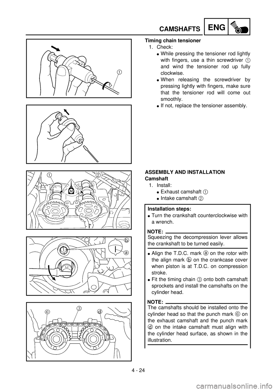
Timing chain tensioner
1. Check:
lWhile pressing the tensioner rod lightly
with fingers, use a thin screwdriver 1
and wind the tensioner rod up fully
clockwise.
lWhen releasing the screwdriver by
pressing lightly with fingers, make sure
that the tensioner rod will come out
smoothly.
lIf not, replace the tensioner assembly.
ASSEMBLY AND INSTALLATION
Camshaft
1. Install:
lExhaust camshaft 1
lIntake camshaft 2
Installation steps:
lTurn the crankshaft counterclockwise with
a wrench.
NOTE:
Squeezing the decompression lever allows
the crankshaft to be turned easily.
lAlign the T.D.C. mark a on the rotor with
the align mark b on the crankcase cover
when piston is at T.D.C. on compression
stroke.
lFit the timing chain 3 onto both camshaft
sprockets and install the camshafts on the
cylinder head.
NOTE:
The camshafts should be installed onto the
cylinder head so that the punch mark c on
the exhaust camshaft and the punch mark
d on the intake camshaft must align with
the cylinder head surface, as shown in the
illustration.
Page 303 of 656

ENG
4 - 24
ARBRES A CAMES
NOCKENWELLE
ALBERI A CAMME
Steuerkettenspanner
1. Kontrollieren:
lDen Steuerkettenspanner-
kopf leicht mit dem Finger
eindrücken und den Span-
ner mit einem dünnen
Schraubendreher 1 im Uhr-
zeigersinn aufdrehen.
lDen Schraubendreher durch
leichten Fingerdruck auf
dem Spannerkopf befreien;
sicherstellen, daß sich der
Spannerkopf dabei leicht-
gängig löst.
lAnderenfalls den Steuerket-
tenspanner (komplett) er-
neuern.
ZUSAMMENBAU UND MONTAGE
Nockenwelle
1. Montieren:
lAuslaß-Nockenwelle 1
lEinlaß-Nockenwelle 2
Arbeitsschritte
lKurbelwelle mit einem Schrau-
benschlüssel gegen den Uhr-
zeigersinn drehen.
HINWEIS:
Durch Drücken des Dekompressi-
onshebels läßt sich die Kurbel-
welle leichter drehen.
lOberer-Totpunkt-Markierung a
am Rotor mit der Markierung b
am Kurbelgehäusedeckel aus-
richten, wenn der Kolben im
oberen Totpunkt (OT) steht.
lDie Steuerkette 3 auf beide
Nockenwellenräder legen und
die Nockenwellen am Zylinder-
kopf montieren.
HINWEIS:
Die Nockenwellen sollten auf dem
Zylinderkopf installiert werden, so
daß die Stanzmarkierung c an
der Auslaß-Nockenwelle und die
Stanzmarkierung d an der Ein-
laß-Nockenwelle mit der Zylinder-
kopfoberfläche ausgeglichen
sind, wie in der Abbildung gezeigt.
Tendeur de la chaîne de distribution
1. Contrôler:
lTout en comprimant légère-
ment la tige du tendeur à l’aide
du doigt, la visser complète-
ment (tourner dans le sens des
aiguilles d’une montre) en se
servant d’un tournevis fin 1.
lAprès avoir retiré le tournevis
en appuyant légèrement du
doigt, vérifier si la tige du ten-
deur sort sans problème.
lSi elle ne sort pas, remplacer le
tendeur.
ASSEMBLAGE ET MONTAGE
Arbre à cames
1. Monter:
lArbre à cames d’échappement 1
lArbre à cames d’admission 2
Etapes de l’installation:
lTourner le vilebrequin à l’aide
d’une clé dans le sens inverse des
aiguilles d’une montre.
N.B.:
Actionner le levier de décompres-
sion a fin de faciliter la rotation du
rilebrequin.
lAligner le repère de PMH a sur le
rotor le repère d’alignement b sur
le couvercle du carter quand le pis-
ton se trouve au Point Mort Haut
(PMH) sur la courge de compres-
sion.
lPlacer la chaîne de distribution 3
sur les deux pignons d’arbre à
cames et installer les arbres à
cames dans la culasse.
N.B.:
Monter les arbres à cames dans la
culasse en veillant à ce que le repère
poinçonné c de l’arbre à cames
d’échappment et le repère poinçonné
d de l’arbre à cames d’admission
s’alignent sur la surface de la culasse,
comme illustré.
Tenditore catena di distribuzione
1. Controllare:
lPremendo leggermente l’asta
del tenditore con le dita, utiliz-
zare un cacciavite sottile 1 e
far ruotare completamente
l’asta del tenditore in senso
orario.
lQuando si rilascia il cacciavite
premendo leggermente con le
dita, accertarsi che l’asta del
tenditore fuoriesca agevol-
mente.
lAltrimenti, sostituire il gruppo
tenditore.
MONTAGGIO ED INSTALLA-
ZIONE
Albero a camme
1. Installare:
lAlbero a camme di scarico 1
lAlbero a camme di ammissione
2
Fasi di installazione:
lRuotare l’albero motore in senso
antiorario con una chiave.
NOTA:
Schiacciando la leva di decompres-
sione la rotazione dell’albero motore
è agevole.
lAllineare il riferimento PMS a sul
rotore al riferimento b sul coper-
chio del carter quando il pistone si
trova nel PMS nella fase di com-
pressione.
lInserire la catena di distribuzione
3 sulle due ruote dentate
dell’albero a camme e montare
l’albero a camme sulla testata del
cilindro.
NOTA:
L’albero a camme va montato sulla
testata del cilindro in modo tale che
la punzonatura c sull’albero a
camme di scarico e la punzonatura d
sull’albero a camme di ammissione
siano allineate alla superficie della
testata del cilindro, come illustrato
nella figura.
Page 304 of 656

4 - 25
ENGCAMSHAFTS
CAUTION:
Do not turn the crankshaft during the
camshaft installation. Damage or
improper valve timing will result.
lInstall the clips, camshaft caps 4 and
bolts (camshaft cap) 5.
T R..
Bolt (camshaft cap):
10 Nm (1.0 m • kg, 7.2 ft • lb)
NOTE:
lBefore removing the clips, cover the cylin-
der head with a clean rag to prevent the
clips from into the cylinder head cavity.
lApply the engine oil on the thread and con-
tact surface of the bolts (camshaft cap).
lTighten the bolts (camshaft cap) 5 in a
crisscross pattern.
CAUTION:
The bolts (camshaft cap) must be tight-
ened evenly or damage to the cylinder
head, camshaft caps and camshaft will
result.
2. Install:
lTiming chain tensioner
Installation steps:
lWhile pressing the tensioner rod lightly
with fingers, use a thin screwdriver and
wind the tensioner rod up fully clockwise.
lWith the rod fully wound and the chain
tensioner UP mark a facing upward,
install the gasket 1 and the timing chain
tensioner 2, and tighten the bolt 3 to the
specified torque.
T R..
Bolt (timing chain tensioner):
10 Nm (1.0 m • kg, 7.2 ft • lb)