1993 DODGE TRUCK clock
[x] Cancel search: clockPage 675 of 1502
INSTALLATION
Only one main bearing should be selectively fitted
while all other main bearing caps are properly tight ened. All bearing capbolts removed during service
procedures are to be cleaned and oiled before instal lation. When installing a new upper bearing shell, slightly
chamfer the sharp edges from the plain side.
(1) Start bearing in place, and insert Crankshaft
Main Bearing Remover/Installer Tool C-3059 into oil
hole of crankshaft (Fig. 19).
(2) Slowly rotate crankshaft counterclockwise slid
ing the bearing into position. Remove Tool C-3059.
(3) Install the bearing cap. Clean and oil the bolts.
Tighten the capbolts to 115 N»m (85 ft. lbs.) torque.
(4) Install the oil pump.
(5) Install the oil pan.
CRANKSHAFT REAR
OIL
SEALS
The service seal is a 2 piece, viton seal. The upper
seal half can be installed with crankshaft removed
from engine or with crankshaft installed. When a
new upper seal is installed, install a new lower seal.
The lower seal half can only be installed with the rear main bearing cap removed.
UPPER SEAL REPLACEMENT (CRANKSHAFT
REMOVED) (1) Remove the crankshaft. (2) Lightly oil the new upper seal lips with engine
oil.
(3) Install the new upper rear bearing oil seal with
the yellow paint facing towards the rear of the en
gine.
(4) Position the crankshaft into the cylinder block.
(5) Lightly oil the new lower seal lips with engine
oil.
(6) Install the new lower rear bearing oil seal into
the bearing cap with the yellow paint facing towards the rear of the engine. (7) Apply 5 mm (0.20 in) drop of Loctite 515, or
equivalent, on each side of the rear main bearing cap (Fig. 16). Do not over apply sealant or allow the seal
ant to contact the rubber seal. Assemble bearing cap
to cylinder block immediately after sealant applica
tion.
(8) To align the bearing cap, use cap slot, align
ment dowel and cap bolts. Do not remove excess ma
terial after assembly. Do not strike rear cap more
than 2 times for proper engagement.
(9) Clean and oil all cap bolts. Install all main
bearing caps. Install all cap bolts and alternately tighten to 115 N*m (85 ft. lbs.) torque. (10) Install oil pump.
(11) Apply Mopar Silicone Rubber Adhesive Seal
ant, or equivalent, at bearing cap to block joint to
provide cap to block and oil pan sealing (Fig. 17). Ap ply enough sealant until a small amount is squeezed
out. Withdraw nozzle and wipe excess sealant off the
oil pan seal groove. (12) Install new front crankshaft oil seal.
(13) Immediately install the oil pan.
UPPER SEAL
REPLACEMENT (CRANKSHAFT
INSTALLED)
(1) Remove the oil pan.
(2) Remove the oil pump from the rear main bear
ing cap.
(3) Remove the rear main bearing cap. Remove
and discard the old lower oil seal.
(4)
Carefully remove and discard the old upper oil
seal.
(5)
Lightly oil the new upper seal lips with engine
oil.
To allow ease of installation of the seal, loosen at
least the 2 main bearing caps forward of the rear
bearing cap.
(6) Rotate the new upper seal into the cylinder
block being careful not to shave or cut the outer sur face of the seal. To assure proper installation, use the installation tool provided with the kit. Install the
new seal with the yellow paint facing towards the
rear of the engine.
(7) Install the new lower rear bearing oil seal into
the bearing cap with the yellow paint facing towards
the rear of the engine.
(8) Apply 5 mm (0.20 in) drop of Loctite 515, or
equivalent, on each side of the rear main bearing cap (Fig. 16). Do not over apply sealant or allow the seal
ant to contact the rubber seal. Assemble bearing cap
to cylinder block immediately after sealant applica
tion. Be sure the yellow paint faces toward the rear of the engine. (9) To align the bearing cap, use cap slot, align
ment dowel and cap bolts. Do not remove excess ma
terial after assembly. Do not strike rear cap more than 2 times for proper engagement. (10) Install the rear main bearing cap with cleaned
and oiled cap bolts. Alternately tighten ALL cap
bolts to 115 N*m (85 ft. lbs.) torque. (11) Install oil pump.
(12) Apply Mopar Silicone Rubber Adhesive Seal
ant, or equivalent, at bearing cap to block joint to
provide cap to block and oil pan sealing (Fig. 17). Ap
ply enough sealant until a small amount is squeezed out. Withdraw nozzle and wipe excess sealant off the
oil pan seal groove. (13) Immediately install the oil pan.
LOWER SEAL REPLACEMENT (1) Remove the oil pan.
(2)
Remove the oil pump from the rear main bear
ing cap. (3) Remove the rear main bearing cap and discard
the old lower seal.
Page 682 of 1502
5.9L
ENGINE SERVICE PROCEDURES
INDEX
page
Camshaft
91
Crankshaft
98
Crankshaft Main Bearings
99
Crankshaft Rear
Oil
Seals
100
Cylinder
Block
101
Cylinder
Head Cover
81
Cylinder
Heads
82
Distributor
92
Engine Assembly
80
Engine
Front
Mounts
77
Engine Rear Mount
78
Front
Crankshaft
Oil
Seal Replacement
91
page
General
Information
77
Hydraulic
Tappets
87
Oil
Pan 93
Oil Pump
. 94
Piston
/
Connecting
Rod
Assembly
96
Rocker Arms
81
Specifications—5.9L
Engine
103
Timing
Chain Cover
89
Valve Stem Shield
/
Spring Replacement
86
Valve
Timing
. 88
Valves
/
Valve Springs
84
Vibration
Damper
88
GENERAL
INFORMATION
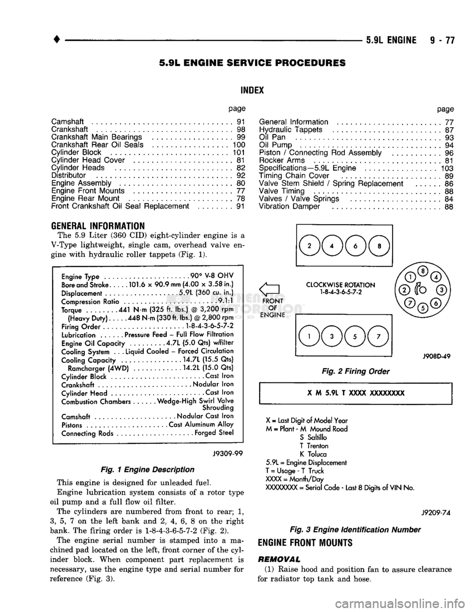
The 5.9 Liter (360 CID) eight-cylinder engine is a
V-Type lightweight, single cam, overhead valve en
gine with hydraulic roller tappets (Fig. 1).
Engine Type .90° V-8 OHV
Bore and Stroke 101.6 x 90.9
mm
(4.00 x 3.58 in.)
Displacement 5.9L (360 cu. in.)
Compression Ratio 9.1:1
Torque 441 N-m (325 ft. lbs.) @ 3,200 rpm (Heavy Duty). 448 N-m (330 ft. lbs.)
@
2,800 rpm
Firing Order
1-8-4-3-6-5-7-2
Lubrication ...... Pressure Feed - Full Flow Filtration
Engine Oil Capacity .4.7L (5.0 Qts) w/filter
Cooling System . .
.
Liquid Cooled - Forced Circulation Cooling Capacity ..... . . 14.7L (15.5 Qts)
Ramcharger (4WD) 14.2L (15.0 Qts)
Cylinder Block Cast Iron Crankshaft
-
Nodular Iron
Cylinder Head • . Cast Iron Combustion Chambers Wedge-High Swirl Valve
Shrouding
Camshaft Nodular Cast Iron Pistons Cast Aluminum Alloy
Connecting Rods Forged Steel
J9309-99
Fig. 1
Engine
Description
This engine is designed for unleaded fuel.
Engine lubrication system consists of a rotor type
oil pump and a full flow oil filter.
The cylinders are numbered from front to rear; 1,
3,
5, 7 on the left bank and 2, 4, 6, 8 on the right
bank. The firing order is
1-8-4-3-6-5-7-2
(Fig. 2).
The engine serial number is stamped into a ma
chined pad located on the left, front corner of the cyl
inder block. When component part replacement is
necessary, use the engine type and serial number for
reference (Fig. 3).
o
FRONT OF
ENGINE CLOCKWISE ROTATION
1-8-4-3-6-5-7-2
J908D-49
Fig. 2 Firing Order
X
M 5.9L T
XXXX
XXXXXXXX
X
= Last Digit of Model Year
M = Plant - M Mound Road S Saltillo
T Trenton K Toluca
5.9L = Engine Displacement
T
= Usage -
T
Truck
XXXX
= Month/Day
XXXXXXXX
= Serial Code - Last 8 Digits of
VIN
No.
J9209-74
Fig.
3
Engine
identification
Number
ENGINE
FRONT MOUNTS
REMOVAL (1) Raise hood and position fan to assure clearance
for radiator top tank and hose.
Page 693 of 1502
9
- 88 5.9L
ENGINE
•
CAUTION:
The
plunger
and
tappet
bodies
are not
interchangeable,.
The
plunger
and
valve must
al
ways
be
fitted
to the
original
body,
It is
advisable
to
work
on one
tappet
at a time to
avoid mixing
of
parts. Mixed parts
are not
compatible.
DO
NOT dis
assemble
a
tappet
on a dirty
work bench.
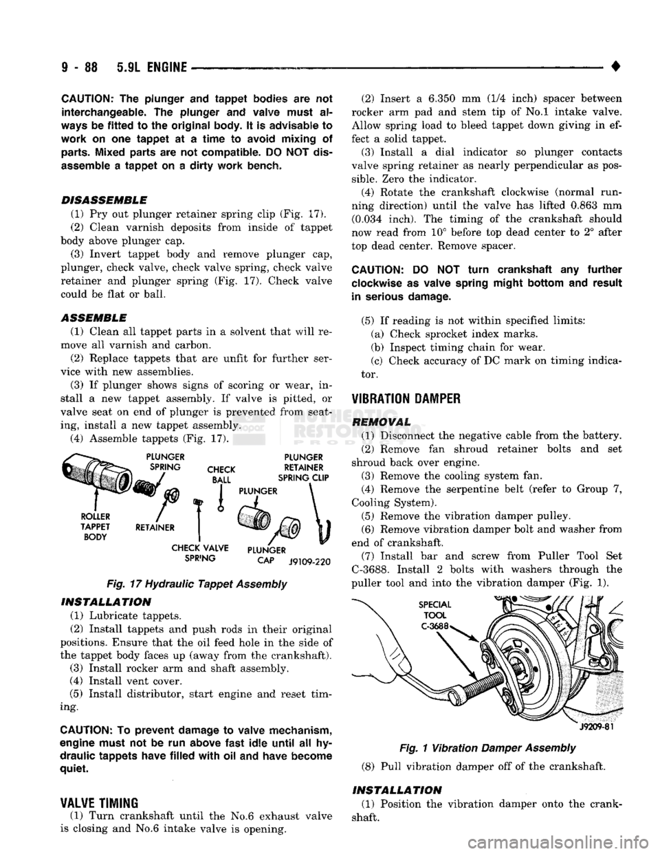
DISASSEMBLE (1) Pry out plunger retainer spring clip (Fig. 17).
(2) Clean varnish deposits from inside of tappet
body above plunger cap.
(3) Invert tappet body and remove plunger cap,
plunger, check valve, check valve spring, check valve
retainer and plunger spring (Fig, 17). Check valve
could be flat or ball.
ASSEMBLE
(1) Clean all tappet parts in a solvent that will re
move all varnish and carbon. (2) Replace tappets that are unfit for further ser
vice with new assemblies.
(3) If plunger shows signs of scoring or wear, in
stall a new tappet assembly. If valve is pitted, or
valve seat on end of plunger is prevented from seat ing, install a new tappet assembly.
(4) Assemble tappets (Fig. 17).
SPiING
CAP J9109-220
Fig.
17 Hydraulic
Tappet
Assembly INSTALLATION
(1) Lubricate tappets.
(2) Install tappets and push rods in their original
positions. Ensure that the oil feed hole In the side of
the tappet body faces up (away from the crankshaft). (3) Install rocker arm and shaft assembly.
(4) Install vent cover.
(5) Install distributor, start engine and reset tim
ing.
CAUTION:
To
prevent damage
to
valve mechanism,
engine must
not be run
above
fast
idle
until
all hy
draulic tappets have
filled
with oil and
have become
quiet.
¥AL¥E
TIMING
(1) Turn crankshaft until the No.6 exhaust valve
is closing and No.6 intake valve Is opening. (2) Insert a 6.350 mm (1/4 inch) spacer between
rocker arm pad and stem tip of No.l intake valve.
Allow spring load to bleed tappet down giving in ef
fect a solid tappet. (3) Install a dial indicator so plunger contacts
valve spring retainer as nearly perpendicular as pos
sible.
Zero the Indicator.
(4) Rotate the crankshaft clockwise (normal run
ning direction) until the valve has lifted 0.863 mm (0.034 inch). The timing of the crankshaft should
now read from 10° before top dead center to 2° after
top dead center. Remove spacer.
CAUTION:
DO NOT
turn crankshaft
any
further
clockwise
as
valve spring might bottom
and
result
in serious damage.
(5) If reading is not within specified limits: (a) Check sprocket index marks.
(b) Inspect timing chain for wear.
(c) Check accuracy of DC mark on timing indica
tor. -
¥IBRATI0N
PAMPER
REMOVAL (1) Disconnect the negative cable from the battery.
(2) Remove fan shroud retainer bolts and set
shroud back over engine. (3) Remove the cooling system fan.
(4) Remove the serpentine belt (refer to Group 7,
Cooling System). (5) Remove the vibration damper pulley. (6) Remove vibration damper bolt and washer from
end of crankshaft. (7) Install bar and screw from Puller Tool Set
C-3688. Install 2 bolts with washers through the
puller tool and into the vibration damper (Fig. 1).
J9209-81
Fig.
1
Vibration
Damper
Assembly
(8) Pull vibration damper off of the crankshaft.
INSTALLATION (1) Position the vibration damper onto the crank
shaft.
Page 704 of 1502
•
5.9L ENGINE
9 - 99
BEARING
CAP
J9309-72
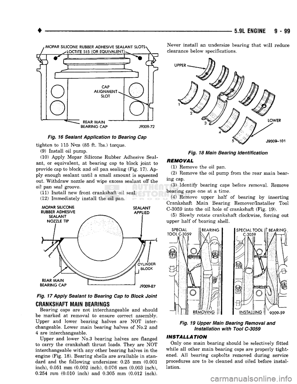
Fig.
16 Sealant Application to Bearing Cap tighten to 115 N-m (85 ft. lbs.) torque.
(9) Install oil pump.
(10) Apply Mopar Silicone Rubber Adhesive Seal
ant, or equivalent, at bearing cap to block joint to
provide cap to block and oil pan sealing (Fig. 17). Ap
ply enough sealant until a small amount is squeezed out. Withdraw nozzle and wipe excess sealant off the
oil pan seal groove. (11) Install new front crankshaft oil seal. (12) Immediately install the oil pan.
MOPAR SILICONE SEALANT
RUBBER
ADHESIVE APPLIED
Fig.
17
Apply
Sealant to Bearing Cap to
Block
Joint
CRANKSHAFT
MAIN BEARINGS
Bearing caps are not interchangeable and should
be marked at removal to ensure correct assembly. Upper and lower bearing halves are NOT inter
changeable. Lower main bearing halves of No.2 and
4 are interchangeable. Upper and lower No.3 bearing halves are flanged
to carry the crankshaft thrust loads. They are NOT interchangeable with any other bearing halves in the
engine (Fig. 18). Bearing shells are available in stan
dard and the following undersizes: 0.25 mm (0.001
inch),
0.051 mm (0.002 inch), 0.076 mm (0.003 inch), 0.254 mm (0.010 inch) and 0.305 mm (0.012 inch). Never install an undersize bearing that will reduce
clearance below specifications.
Fig.
18 Main Bearing
Identification
REMOVAL (1) Remove the oil pan.
(2) Remove the oil pump from the rear main bear
ing cap. (3) Identify bearing caps before removal. Remove
bearing caps one at a time.
(4) Remove upper half of bearing by inserting
Crankshaft Main Bearing Remover/Installer Tool
C-3059 into the oil hole of crankshaft (Fig. 19).
(5) Slowly rotate crankshaft clockwise, forcing out
upper half of bearing shell.
Fig.
19 Upper Main Bearing
Removal
and
Installation
with
Tool C-3059
INSTALLATION
Only one main bearing should be selectively fitted
while all other main bearing caps are properly tight ened. All bearing capbolts removed during service
procedures are to be cleaned and oiled before instal lation.
Page 705 of 1502
9
- 100 5.9L
ENGINE
• When installing a new upper bearing shell, slightly
chamfer the sharp edges from the plain side. (1) Start bearing in place, and insert Crankshaft
Main Bearing Remover/Installer Tool C-3059 into oil
hole of crankshaft (Fig. 16).
(2) Slowly rotate crankshaft counterclockwise slid
ing the bearing into position. Remove Tool C-3059.
(3) Install the bearing cap. Clean and oil the bolts.
Tighten the capbolts to 115 N»m (85 ft. lbs.) torque.
(4) Install the oil pump.
(5) Install the oil pan.
CRANKSHAFT REAR
OIL
SEALS
The service seal is a 2 piece, viton seal. The upper
seal half can be installed with crankshaft removed
from engine or with crankshaft installed. When a
new upper seal is installed, install a new lower seal.
The lower seal half can only be installed with the
rear main bearing cap removed.
UPPER SEAL REPLACEMENT (CRANKSHAFT
REMOVED)
(1) Remove the crankshaft.
(2) Lightly oil the new upper seal lips with engine
oil.
(3) Install the new upper rear bearing oil seal with
the yellow paint facing towards the rear of the en
gine.
(4) Position the crankshaft into the cylinder block.
(5) Lightly oil the new lower seal lips with engine
oil.
(6) Install the new lower rear bearing oil seal into
the bearing cap with the yellow paint facing towards
the rear of the engine.
(7) Apply 5 mm (0.20 in) drop of Loctite 515, or
equivalent, on each side of the rear main bearing cap (Fig. 16). Do not over apply sealant or allow the seal
ant to contact the rubber seal. Assemble bearing cap
to cylinder block immediately after sealant applica
tion.
(8) To align the bearing cap, use cap slot, align
ment dowel and cap bolts. Do not remove excess ma
terial after assembly. Do not strike rear cap more
than 2 times for proper engagement.
(9) Clean and oil all cap bolts. Install all main
bearing caps. Install all cap bolts and alternately
tighten to 115
Nth
(85 ft. lbs.) torque. (10) Install oil pump.
(11) Apply Mopar Silicone Rubber Adhesive Seal
ant, or equivalent, at bearing cap to block joint to
provide cap to block and oil pan sealing (Fig. 17). Ap
ply enough sealant until a small amount is squeezed
out. Withdraw nozzle and wipe excess sealant off the
oil pan seal groove.
(12) Install new front crankshaft oil seal.
(13) Immediately install the oil pan. UPPER SEAL REPLACEMENT (CRANKSHAFT
INSTALLED)
(1) Remove the oil pan.
(2) Remove the oil pump from the rear main bear
ing cap. (3) Remove the rear main bearing cap. Remove
and discard the old lower oil seal. (4) Carefully remove and discard the old upper oil
seal. (5) Lightly oil the new upper seal lips with engine
oil.
To allow ease of installation of the seal, loosen at least the 2 main bearing caps forward of the rear
bearing cap.
(6) Rotate the new upper seal into the cylinder
block being careful not to shave or cut the outer sur face of the seal. To assure proper installation, use the installation tool provided with the kit. Install the
new seal with the yellow paint facing towards the
rear of the engine.
(7) Install the new lower rear bearing oil seal into
the bearing cap with the yellow paint facing towards
the rear of the engine.
(8) Apply 5 mm (0.20 in) drop of Loctite 515, or
equivalent, on each side of the rear main bearing cap (Fig. 16). Do not over apply sealant or allow the seal
ant to contact the rubber seal. Assemble bearing cap
to cylinder block immediately after sealant applica
tion. Be sure the yellow paint faces toward the rear of the engine.
(9) To align the bearing cap, use cap slot, align
ment dowel and cap bolts. Do not remove excess ma
terial after assembly. Do not strike rear cap more
than 2 times for proper engagement.
(10) Install the rear main bearing cap with cleaned
and oiled cap bolts. Alternately tighten ALL cap
bolts to 115 N*m (85 ft. lbs.) torque.
(11) Install oil pump.
(12) Apply Mopar Silicone Rubber Adhesive Seal
ant, or equivalent, at bearing cap to block joint to
provide cap to block and oil pan sealing (Fig. 17). Ap
ply enough sealant until a small amount is squeezed out. Withdraw nozzle and wipe excess sealant off the
oil pan seal groove.
(13) Immediately install the oil pan.
LOWER SEAL REPLACEMENT (1) Remove the oil pan.
(2) Remove the oil pump from the rear main bear
ing cap. (3) Remove the rear main bearing cap and discard
the old lower seal. (4) Carefully install a new upper seal (refer to Up
per Seal Replacement - Crankshaft Installed proce dure above). (5) Lightly oil the new lower seal lips with engine
oil.
(6) Install a new lower seal in bearing cap with
yellow paint facing the rear of engine.
Page 715 of 1502
9
- 119 5.9L
(DIESEL) ENGINE
Fig.
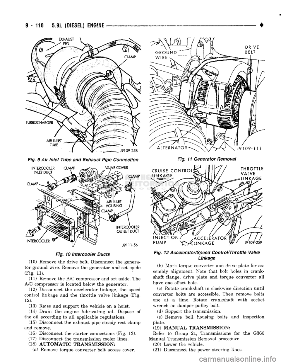
10 intercooler
Ducts
(10) Remove the drive belt. Disconnect the genera
tor ground wire. Remove the generator and set aside (Fig. 11).
(11) Remove the A/0 compressor and set aside. The
A/C compressor is located below the generator. (12) Disconnect the accelerator linkage, the speed
control linkage and the throttle valve linkage (Fig.
12).
(13) Raise and support the vehicle on a hoist.
(14)
Drain the engine lubricating oil. Dispose of
the oil according to all applicable regulations. (15) Disconnect the exhaust pipe steady rest clamp
and remove. (16) Disconnect the starter connections (Fig. 13).
(17) Disconnect the transmission cooler lines.
(18) AUTOMATIC TRANSMISSION: (a) Remove torque converter bolt access cover. •
Fig, 11 Generator Removal
Fig. 12 Accelerator/Speed
Control/Throttle
Valve
Linkage
(b) Mark
torque
converter and
drive
plate for
as
sembly
alignment.
Note
that bolt
holes
in crank
shaft flange, drive plate and torque converter all
have
one offset hole.
(c) Rotate crankshaft in clockwise direction until
converter
bolts
are accessible. Then remove
bolts
one
at a
time.
Rotate crankshaft with socket wrench on damper pulley bolt.
(d) Support the transmission.
(e)
Remove bell housing bolts and inspection
plate. (19) MANUAL TRANSMISSION:
Refer to Group 21, Transmissions for the G360
Manual Transmission Removal procedure. (20) Lower the vehicle.
(21) Disconnect the power steering lines.
Page 717 of 1502
9
- 112 5.9L
(DIESEL)
ENGINE
• (5) Position the engine in the chassis and install
the through bolt. Tighten the through bolt nut to 41
N-m (30 ft. lbs.) torque. (6) Make sure the lifting brackets are mounted
with the eye down. (7) Remove the covers or tape covering the engine
openings. (8) Connect the fuel lines to the lift pump and fuel
return.
(9) Connect all electrical connections.
(10) Connect the power steering lines.
(11) Raise and support the vehicle on a hoist.
(12) AUTOMATIC TRANSMISSION:
CAUTION:
If new
flex
plate is installed, remove
flashing
from the engine
back
plate at the 5 and 7
o'clock
positions.
(a) Rotate converter until alignment mark on the
converter is aligned with mark on drive plate.
Off
set holes in plate are next to 1/8 inch hole in inner
circle of drive plate.
(b) Install bell housing bolts. Tighten the bolts to
41 N-m (30 ft. lbs.) torque. (c) With the torque converter plate aligned to the
torque converter, install and tighten the bolts to 31 N-m (270 in. lbs.) torque. (d) Install the converter housing access plate.
(e) Remove the transmission support.
(13) MANUAL TRANSMISSION:
Refer to Group 21, Transmissions for the G360
Manual Transmission Installation procedure. (14) Connect the ground cable and tighten the nut
to 22 N-m (16 ft. lbs.) torque. Connect the solenoid cable and tighten the nut to 5 N-m (44 in. lbs.)
torque.
(15) Connect the transmission cooler lines.
(16) Install the exhaust pipe to the exhaust sys
tem.
(17) Lower the vehicle.
(18) Install the A/C compressor and tighten the
bolts to 47 N-m (35 ft. lbs.) torque. If removed, con nect the clutch electrical wire.
(19) Install the generator. Tighten the upper
mounting bolts to 24 N-m (18 ft. lbs.) torque. Now
tighten the lower mounting bolts to 43 N-m (32 ft. lbs.) torque. Connect all wires.
(20) Install the radiator, fan/fan clutch assembly
and fan shroud (refer to Group 7, Cooling Systems
for the proper procedures). Connect the radiator
hoses.
(21) Position the intercooler inlet duct to the tur
bocharger and the intercooler. With the clamps in po sition, tighten the clamp nut to 8 N-m (72 in. lbs.)
torque. (22) Position the intercooler outlet duct to the air
inlet housing and the intercooler. With the clamps in
position, tighten the clamp nut to 8 N-m (72 in. lbs.)
torque.
(23) Connect the air intake tube to the turbo
charger inlet flange and the air cleaner housing.
Tighten the clamps to 8 N-m (72 in. lbs.) torque. (24) Install the exhaust pipe to the turbocharger.
Tighten the steady rest clamp to 8 N-m (72 in. lbs.) torque.
(25) Make sure the air intake and exhaust pipe
connections are tight and free of leaks.
(26) Fill the engine with the required amount of
clean engine lubricating oil (refer to Group 0, Lubri cation and Maintenance).
(27) Fill the cooling system with a mixture of 50%
water and 50% ethylene-glycol base antifreeze (refer Group 7, Cooling System for the proper procedure).
(28) Install the battery and connect the battery ca
bles.
(29) Check the oil level after the engine has run
for 2 or 3 minutes. Oil held in the oil filter and oil passages will cause the oil level in the pan to be lower.
(30) Operate the engine at idle for 5 to 10 minutes
and check for leaks and loose parts.
ROCKER LEVERS
/
POSH
RODS
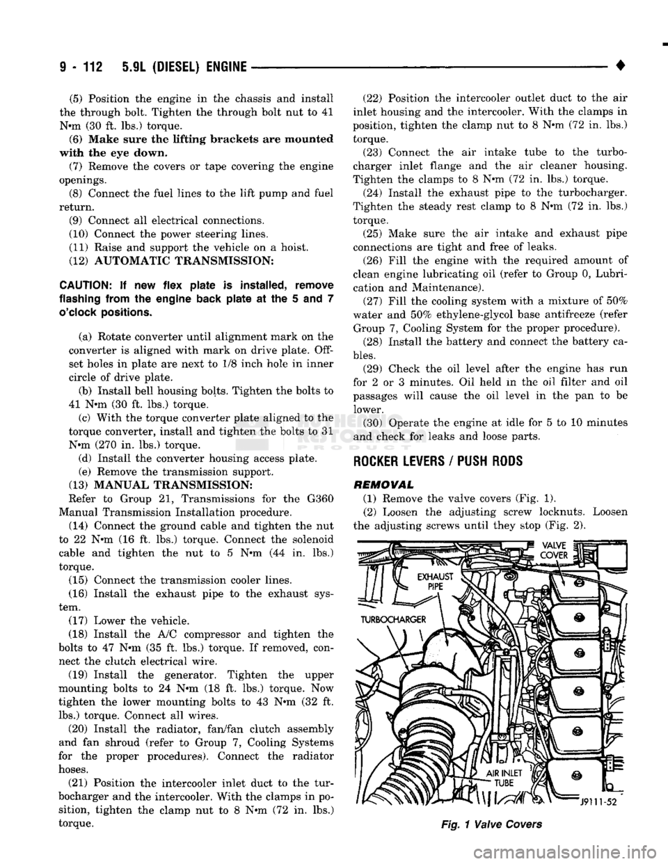
REMOVAL (1) Remove the valve covers (Fig. 1). (2) Loosen the adjusting screw locknuts. Loosen
the adjusting screws until they stop (Fig. 2).
Page 728 of 1502
•
5.9L
(DIESEL)
ENGINE
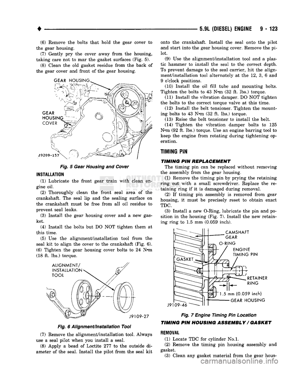
9 - 123 (6) Remove the bolts that hold the gear cover to
the gear housing. (7) Gently pry the cover away from the housing,
taking care not to mar the gasket surfaces (Fig. 5). (8) Clean the old gasket residue from the back of
the gear cover and front of the gear housing.
Fig.
5 Gear
Housing
and
Cover
INSTALLATION
(1) Lubricate the front gear train with clean en
gine oil.
(2) Thoroughly clean the front seal area of the
crankshaft. The seal lip and the sealing surface on
the crankshaft must be free from all oil residue to
prevent seal leaks.
(3) Install the gear housing cover and a new gas
ket.
(4) Install the bolts but DO NOT tighten them at
this time.
(5) Use the alignment/installation tool from the
seal kit to align the cover to the crankshaft (Fig. 6). (6) Tighten the gear housing cover bolts to 24 N*m
(18 ft. lbs.) torque.
Fig.
6 Alignment/Installation Tool
(7) Remove the alignment/installation tool. Always
use a seal pilot when you install a seal.
(8) Apply a bead of Loctite 277 to the outside di
ameter of the seal. Install the pilot from the seal kit onto the crankshaft. Install the seal onto the pilot
and start into the gear housing cover. Remove the pi
lot. (9) Use the alignment/installation tool and a plas
tic hammer to install the seal to the correct depth.
To prevent damage to the seal carrier, hit the align ment/installation tool alternately at the 12, 3, 6 and 9 o'clock positions.
(10) Install the oil fill tube and mounting bolts.
Tighten the bolts to 43 N*m (32 ft. lbs.) torque. (11) Install the vibration damper. DO NOT tighten
the bolts to the correct torque valve at this time.
(12) Install the belt tensioner. Tighten the mount
ing bolts to 43 Nnn (32 ft. lbs.) torque. (13) Raise the belt tensioner to install the belt.
(14) Tighten the vibration damper bolts to 125
N*m (92 ft. lbs.) torque. Use an engine barring tool to keep the engine from rotating during tightening op
eration.
TIMING
PIN TIMING PIN REPLACEMENT The timing pin can be replaced without removing
the assembly from the gear housing. (1) Remove the timing pin by prying the retaining
ring out with a small screwdriver. Replace the re
taining ring if it is damaged during removal.
(2) If timing pin assembly is removed from gear
housing, it must be precisely reset to obtain exact
TDC.
(3) Install a new O-Ring, lubricate the pin and po
sition in the housing (Fig. 7). Install the new retain
ing ring to 1.5 mm (0.059 inch).
Fig.
7
Engine
Timing Pin Location
TIMING PIN HOUSING ASSEMBLY/ GASKET
REMOVAL
(1) Locate TDC for cylinder No.l.
(2) Remove the timing pin housing assembly and
gasket.
(3) Clean any gasket material from the gear hous-