1993 DODGE TRUCK gas codes
[x] Cancel search: gas codesPage 856 of 1502
•
FUEL SYSTEM
14 - 37 used only on vehicles equipped with the 5.9L heavy
duty cycle (HDC) engine. Refer to Group 25, Emis
sion Control System for information.
EVAP CANISTER PURGE SOLENOID-PCM
OUTPUT
Refer to Group 25, Emission Control System. See
EVAP Canister Purge Solenoid.
FUEL INJECTORS-PCM
OUTPUT
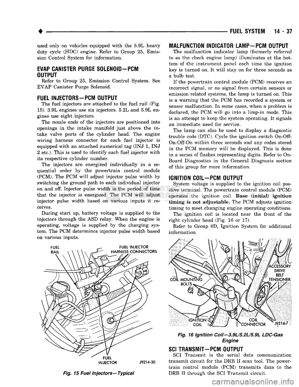
The fuel injectors are attached to the fuel rail (Fig.
15).
3.9L engines use six injectors. 5.2L and 5.9L en
gines use eight injectors. The nozzle ends of the injectors are positioned into
openings in the intake manifold just above the in
take valve ports of the cylinder head. The engine
wiring harness connector for each fuel injector is equipped with an attached numerical tag (INJ 1, INJ 2 etc.). This is used to identify each fuel injector with
its respective cylinder number. The injectors are energized individually in a se
quential order by the powertrain control module (PCM). The PCM will adjust injector pulse width by
switching the ground path to each individual injector
on and off. Injector pulse width is the period of time
that the injector is energized. The PCM will adjust injector pulse width based on various inputs it re
ceives. During start up, battery voltage is supplied to the
injectors through the ASD relay. When the engine is
operating, voltage is supplied by the charging sys
tem. The PCM determines injector pulse width based on various inputs.
FUEL
INJECTOR
J9214-30
Fig.
15
Fuel
injectors—Typical
MALFUNCTION INDICATOR LAMP-PCM OUTPUT
The malfunction indicator lamp (formerly referred
to as the check engine lamp) illuminates at the bot
tom of the instrument panel each time the ignition key is turned on. It will stay on for three seconds as a bulb test. If the powertrain control module (PCM) receives an
incorrect signal, or no signal from certain sensors or
emission related systems, the lamp is turned on. This
is a warning that the PCM has recorded a system or
sensor malfunction. In some cases, when a problem is
declared, the PCM will go into a limp-in mode. This
is an attempt to keep the system operating. It signals an immediate need for service. The lamp can also be used to display a diagnostic
trouble code (DTC). Cycle the ignition switch
On-Off-
On-Off-On within three seconds and any codes stored
in the PCM memory will be displayed. This is done
in a series of flashes representing digits. Refer to On-
Board Diagnostics in the General Diagnosis section
of this group for more information.
IGNITION COIL-PCM OUTPUT
System voltage is supplied to the ignition coil pos
itive terminal. The powertrain control module (PCM)
operates the ignition coil. Base (initial) ignition
timing is not adjustable. The PCM adjusts ignition
timing to meet changing engine operating conditions. The ignition coil is located near the front of the
right cylinder head (Fig. 16 or 17). Refer to Group 8D, Ignition System for additional
information.
Fig.
16 Ignition Coii-3.9U5.2U5.9L
LDC-Gas
Engine
SCI
TRANSMIT—PCM OUTPUT
SCI Transmit is the serial data communication
transmit circuit for the DRB II scan tool. The power- train control module (PCM) transmits data to the DRB II through the SCI Transmit circuit.
Page 867 of 1502
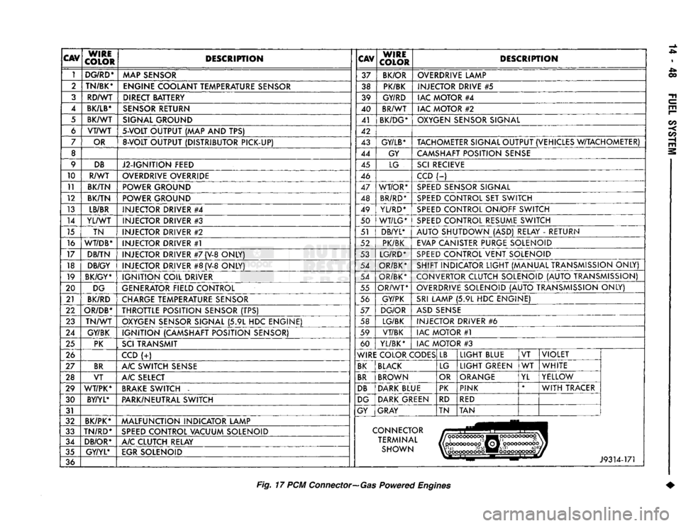
CAV
WIRE
COLOR DESCRIPTION
CAV
WIRE
COLOR DESCRIPTION
1 DG/RD*
MAP SENSOR 37
BK/OR OVERDRIVE LAMP
2 TN/BK*
ENGINE COOLANT TEMPERATURE SENSOR 38 PK/BK INJECTOR DRIVE
#5
3 RD/WT DIRECT BATTERY 39 GY/RD IAC MOTOR
#4
4
BK/LB*
SENSOR RETURN 40 BR/WT
IAC MOTOR
#2
5 BK/WT SIGNAL GROUND 41
BK/DG* OXYGEN SENSOR SIGNAL
6 VT/WT
5-VOLT
OUTPUT
(MAP AND TPS)
42
7 OR
8-VOLT
OUTPUT (DISTRIBUTOR PICK-UP) 43
GY/LB*
TACHOMETER SIGNAL OUTPUT (VEHICLES W/TACHOMETER)
8 44 GY CAMSHAFT POSITION SENSE
9 DB
J2-IGNITION FEED 45
LG SCI RECIEVE
10 R/WT OVERDRIVE OVERRIDE
46 CCD
(-)
11 BK/TN POWER GROUND 47 WT/OR* SPEED SENSOR SIGNAL
12 BK/TN POWER GROUND 48 BR/RD* SPEED CONTROL
SET
SWITCH
13 LB/BR
INJECTOR DRIVER
#4
49
YL/RD* SPEED CONTROL ON/OFF SWITCH
14 YL/WT
INJECTOR DRIVER
#3
50 WT/LG* SPEED CONTROL RESUME SWITCH
15 TN INJECTOR DRIVER
#2
51 DB/YL*
AUTO SHUTDOWN
(ASD)
RELAY
-
RETURN
16
WT/DB*
INJECTOR DRIVER
#1
52 PK/BK
EVAP CANISTER PURGE SOLENOID
17 DB/TN INJECTOR DRIVER
#7
(V-8
ONLY) 53 LG/RD* SPEED CONTROL VENT SOLENOID
18 DB/GY
INJECTOR DRIVER
#8
(V-8
ONLY) 54
OR/BK* SHIFT INDICATOR LIGHT (MANUAL TRANSMISSION ONLY)
19 BK/GY*
IGNITION COIL DRIVER 54
OR/BK* CONVERTOR CLUTCH SOLENOID (AUTO TRANSMISSION)
20 DG
GENERATOR FIELD CONTROL 55
OR/WT OVERDRIVE SOLENOID (AUTO TRANSMISSION ONLY)
21 BK/RD
CHARGE TEMPERATURE SENSOR 56
GY/PK SRI LAMP
(5.9L HDC
ENGINE)
22
OR/DB*
THROTTLE POSITION SENSOR
(TPS)
57
DG/OR ASD SENSE
23 TN/WT
OXYGEN SENSOR SIGNAL
(5.9L HDC
ENGINE) 58 LG/BK
INJECTOR DRIVER
#6
24 GY/BK IGNITION (CAMSHAFT POSITION SENSOR) 59
VT/BK IAC MOTOR
#1
25 PK
,
SCI
TRANSMIT 60
YL/BK* IAC MOTOR
#3
26 CCD
(-:-)
WIRE COLOR CODES LB
LIGHT BLUE
VT VIOLET
27 BR
A/C SWITCH SENSE BK BLACK
LG LIGHT GREEN
WT
WHITE
28 VT A/C SELECT BR BROWN
OR ORANGE
YL YELLOW
29 WT/PK* BRAKE SWITCH
-
DB DARK BLUE PK
PINK *
WITH TRACER
30 BY/YL*
PARK/NEUTRAL SWITCH DG DARK GREEN
RD
RED
31 GY
GRAY TN TAN
32 BK/PK*
MALFUNCTION INDICATOR LAMP
33 TN/RD*
SPEED CONTROL VACUUM SOLENOID CONNECTOR
34 DB/OR* A/C CLUTCH RELAY TERMINAL
|(pcKX>coooop0ffoj'
oooooooooojj
35 GY/YL*
EGR SOLENOID SHOWN W'41
30
50«M#5l31
604
%\
oooooooooo ••ooooooooooj
36 J9314-171
Fig.
17 PCM
Connector—Gas
Powered
Engines
Page 879 of 1502
14 - SO
FUEL
SYSTEM
•
HIGH
AND LOW
LIMITS
The powertrain control module (PCM) compares in
put signal voltages from each input device. It will es
tablish high and low limits that are programmed into it for that device. If the input voltage is not
within specifications and other diagnostic trouble code (DTC) criteria are met, a DTC will be stored in
memory. Other DTC criteria might include engine
rpm limits or input voltages from other sensors or switches. The other inputs might have to be sensed
by the PCM when it senses a high or low input volt age from the control system device in question.
ACCESSING DIAGNOSTIC TROUBLE CODES A stored diagnostic trouble code (DTC) can be dis
played by cycling the ignition key On-Off-On-Off-On
within three seconds and observing the malfunction indicator lamp. This lamp was formerly referred to
as the check engine lamp. The lamp is located on the
instrument panel.
They can also be displayed through the use of the
Diagnostic Readout Box II (DRB II scan tool). The
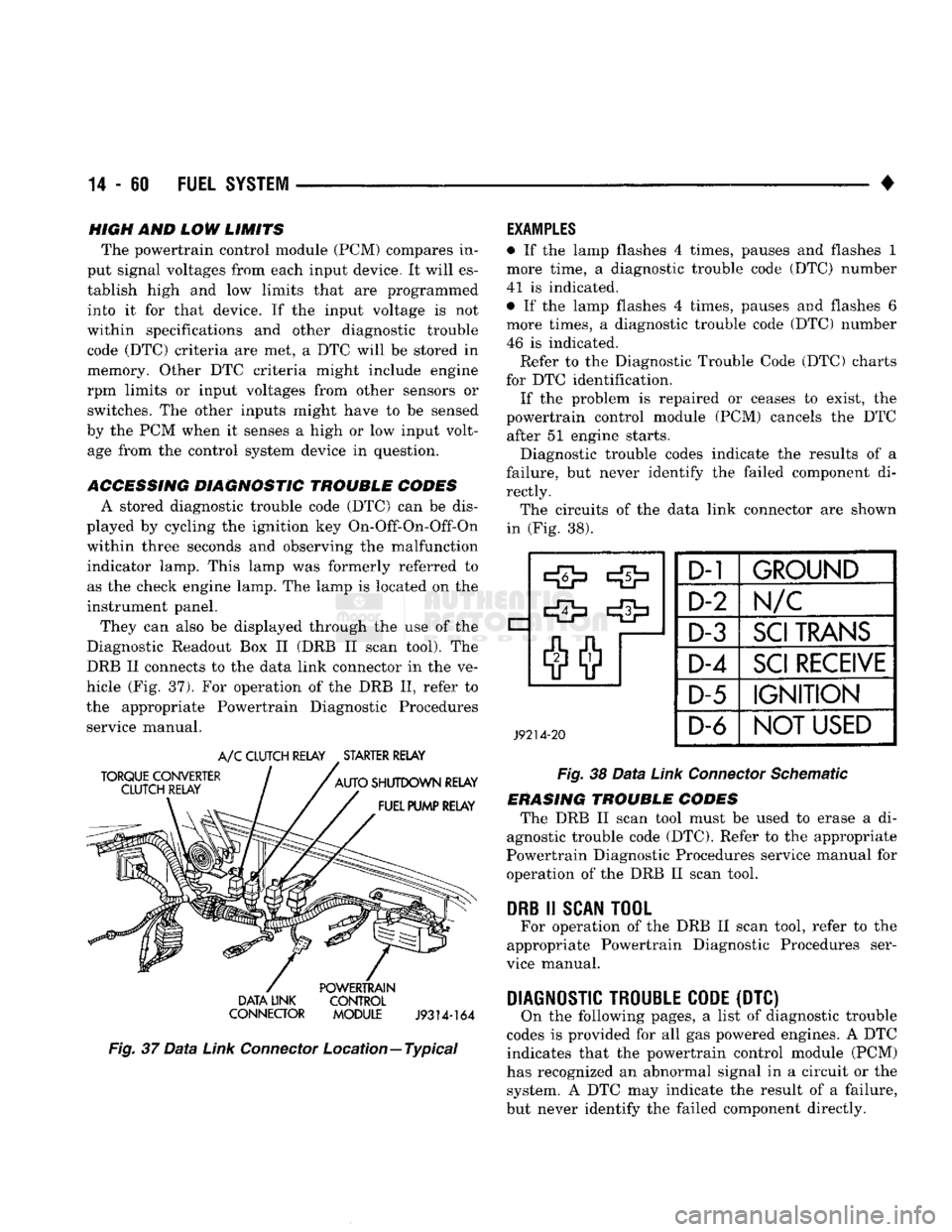
DRB II connects to the data link connector in the ve
hicle (Fig. 37). For operation of the DRB II, refer to
the appropriate Powertrain Diagnostic Procedures service manual.
TORQUE CONVERTER
CLUTCH RELAY
A/C
CLUTCH RELAY
.
STARTER RELAY
AUTO
SHUTDOWN RELAY FUEL PUMP RELAY POWERTRAIN
DATA LINK CONTROL
CONNECTOR MODULE
J9314-164
Fig.
37
Data
Link
Connector
Location—Typical
EXAMPLES
• If the lamp flashes 4 times, pauses and flashes 1
more time, a diagnostic trouble code (DTC) number
41 is indicated.
• If the lamp flashes 4 times, pauses and flashes 6
more times, a diagnostic trouble code (DTC) number
46 is indicated. Refer to the Diagnostic Trouble Code (DTC) charts
for DTC identification. If the problem is repaired or ceases to exist, the
powertrain control module (PCM) cancels the DTC after 51 engine starts.
Diagnostic trouble codes indicate the results of a
failure, but never identify the failed component di
rectly. The circuits of the data link connector are shown
in (Fig. 38).
J9214-20
D-1
GROUND
D-2 Im/c
D-3
SCI
TRANS
D-4
SCI
RECEIVE
D-5
IGNITION
D-6
NOT
USED
Fig.
38
Data
Link
Connector
Schematic
ERASING TROUBLE CODES The DRB II scan tool must be used to erase a di
agnostic trouble code (DTC). Refer to the appropriate
Powertrain Diagnostic Procedures service manual for operation of the DRB II scan tool.
DRB
II
SCAN
TOOL
For operation of the DRB II scan tool, refer to the
appropriate Powertrain Diagnostic Procedures ser
vice manual.
DIAGNOSTIC TROUBLE CODE
(DTC) On the following pages, a list of diagnostic trouble
codes is provided for all gas powered engines. A DTC indicates that the powertrain control module (PCM)
has recognized an abnormal signal in a circuit or the system. A DTC may indicate the result of a failure,
but never identify the failed component directly.
Page 1077 of 1502
21 - 76
AUTOMATIC
TRANSMISSION—32RH/36RH/37RH/42RH/46RH
•
TORQUE
CONVERTER
A three element torque converter is used. The con
verter used with 32RH and some 36RH transmis sions has a modulated converter clutch. The
converter used with 37RH transmissions is not
equipped with a modulated clutch. The converter used with 1993, 32RH transmissions
is new. The converter hub was changed to accept the
new style drive flats on the oil pump inner gear. The
new style converter is not interchangeable with pre
vious designs. A 241 or 273 mm (9.5 or 10.75 in.) converter is
used for 3.9L, 5.2L and 5.9L gas engine applications.
A 310 mm (12.2 in.) converter is used for diesel en
gine applications. The converter impeller is connected to the engine
crankshaft through the front cover which is welded
to the impeller. The turbine is splined to the trans
mission input shaft and the stator is splined to the transmission reaction shaft. The converter is a welded assembly. It is not a re
pairable component and is serviced as an assembly.
RECOMMENDED
FLUID
The recommended and preferred fluid for Chrysler
automatic transmissions is Mopar ATF Plus, Type
7176.
Use Mopar Dexron II only when ATF Plus is
not readily available.
TRANSMISSION
IDENTIFICATION
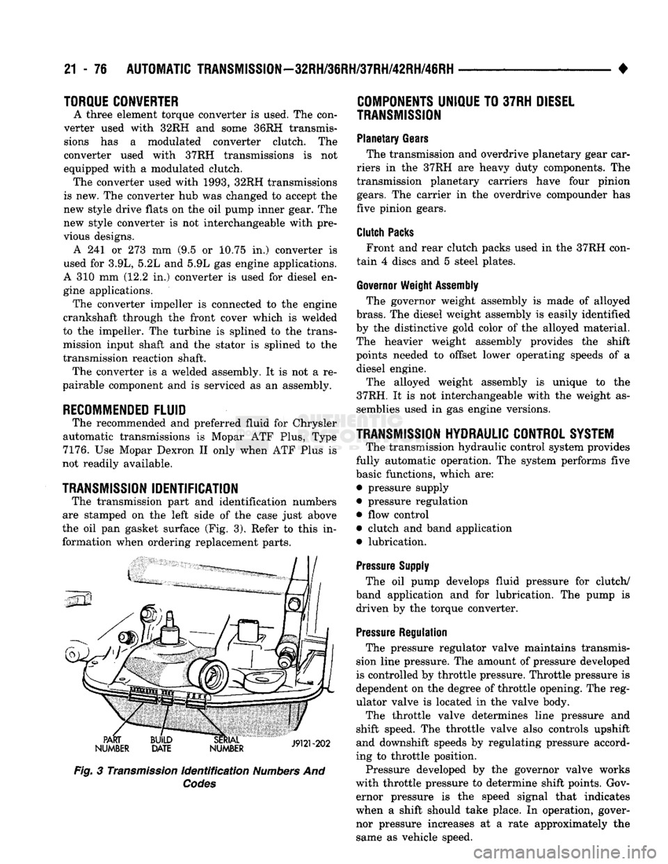
The transmission part and identification numbers
are stamped on the left side of the case just above
the oil pan gasket surface (Fig. 3). Refer to this in formation when ordering replacement parts.
PART
NUMBER BUILD
DATE SERIAL
19191-909
NUMBER JVUI zuz
Fig.
3
Transmission
Identification
Numbers
And
Codes
COMPONENTS
UNIQUE
TO
37RH
DIESEL
TRANSMISSION
Planetary
Gears
The transmission and overdrive planetary gear car
riers in the 37RH are heavy duty components. The
transmission planetary carriers have four pinion
gears.
The carrier in the overdrive compounder has
five pinion gears.
Clutch
Packs
Front and rear clutch packs used in the 37RH con
tain 4 discs and 5 steel plates.
Governor
Weight
Assembly
The governor weight assembly is made of alloyed
brass.
The diesel weight assembly is easily identified
by the distinctive gold color of the alloyed material.
The heavier weight assembly provides the shift
points needed to offset lower operating speeds of a diesel engine.
The alloyed weight assembly is unique to the
37RH. It is not interchangeable with the weight as semblies used in gas engine versions.
TRANSMISSION
HYDRAULIC
CONTROL
SYSTEM
The transmission hydraulic control system provides
fully automatic operation. The system performs five
basic functions, which are: • pressure supply
• pressure regulation • flow control
• clutch and band application
• lubrication.
Pressure
Supply
The oil pump develops fluid pressure for clutch/
band application and for lubrication. The pump is driven by the torque converter.
Pressure
Regulation
The pressure regulator valve maintains transmis
sion line pressure. The amount of pressure developed
is controlled by throttle pressure. Throttle pressure is
dependent on the degree of throttle opening. The reg
ulator valve is located in the valve body.
The throttle valve determines line pressure and
shift speed. The throttle valve also controls upshift
and downshift speeds by regulating pressure accord
ing to throttle position.
Pressure developed by the governor valve works
with throttle pressure to determine shift points. Gov ernor pressure is the speed signal that indicates
when a shift should take place. In operation, gover
nor pressure increases at a rate approximately the same as vehicle speed.
Page 1082 of 1502
•
AUTOMATIC
TRANSMISSION—32RH/36RH/37RH/42RH/46RH
21 - 81
TORQUE
CONVERTER
A three element torque converter
is
used
for all ap
plications.
The
converter consists
of the
impeller,
sta-
tor
and
turbine.
The
converter also contains
an
overrunning clutch
and a
modulated converter clutch
mechanism.
The converter used with
1993,
42RH transmissions
is
new. The
converter
hub was
changed
to
accept
the
new style drive flats
on the oil
pump inner gear.
The
new style converter
is not
interchangeable with pre
vious designs.
The converter modulated clutch consists
of a
slid
ing clutch piston, clutch springs
and the
clutch disc
friction material.
The
clutch provides optimum
torque transfer
and
economy when engaged.
The clutch disc
is
attached
to the
converter front
cover.
The
clutch piston
and
clutch springs
are at
tached
to the
turbine
hub. The
springs dampen
en
gine firing impulses
and
loads during
the
initial
phase
of
converter clutch engagement.
Clutch engagement
is
controlled
by the
converter
clutch valve
and
solenoid. Both
are
located
on the
transmission valve body. Clutch engagement occurs in drive range
at
speeds above approximately 30-35
mph.
The clutch provides reduced engine speed
and
greater fuel economy when engaged. Clutch engage
ment also provides reduced transmission fluid tem
peratures.
COMPONENTS
UNIQUE
TO
DIESEL VERSION
OF
46RH
Planetary
Gears
The transmission
and
overdrive planetary gear car
riers
in the
diesel version
of the
46RH
are
heavy duty components.
The
transmission planetary carriers have four pinion gears.
The
carrier
in the
over
drive compounder
has
five pinion gears.
The
heavy
duty planetary units
are
unique
to the
diesel 46RH.
Clutch
Packs
Clutch packs used
in the
diesel version
of the
46RH contain
the
following number
of
discs
and
plates:
• transmission front/rear clutch
has 4
discs
and 5
steel plates
• overdrive clutch
has 5
discs
and 6
steel plates
• overdrive direct clutch
has 8
discs
and 9
steel
plates
Governor
Weight
Assembly
The governor weight assembly
in the
diesel 46RH
is made
of
alloyed brass.
The
diesel weight assembly
is easily identified
by the
distinctive gold color
of the
alloyed material.
The
heavier weight assembly pro
vides
the
shift points needed
to
offset lower operating speeds
of a
diesel engine. The alloyed weight assembly
is
unique
to the
diesel
46RH.
It is not
interchangeable with
the
weight
as
semblies used
in gas
engine versions.
Diesel
Thermo
Switch
Fourth gear operation
in the
diesel 46RH
is
also
controlled
by two
temperature sensitive thermo- switches.
The first thermo-switch
is the
engine coolant tem
perature switch. This switch prevents overdrive fourth gear operation when engine coolant tempera
ture
is
below approximately
65° F.
The second thermo-switch directly monitors trans
mission fluid temperature.
The
switch will either
downshift
the
transmission
to
third gear,
or
prevent a
3-4
upshift when fluid temperature exceeds
270-275°
F.
The fluid temperature switch
is
located
in a
boss
built into
the
cooler outlet line.
The
boss
and
switch are located approximately
2-3
inches from
the
outlet
line fitting
in the
transmission case.
The engine coolant
and
fluid temperature switches
are
in
circuit with
the
overdrive control switch
in the
instrument panel.
GEAR RATIOS
42RH forward gear ratios
are:
First gear
=
2.74:1
Second gear
= 1.54:1
Third gear
= 1.00:1
Fourth gear
=
0.69:1.
46RH forward gear ratios
are:
First gear
=
2.45:1 Second gear
= 1.45:1
Third gear
= 1.00:1
Fourth gear
=
0.69:1.
RECOMMENDED
FLUID
The recommended
and
preferred fluid
for
42RH/
46RH transmissions
is
Mopar
ATF
Plus, type
7176.
Use Mopar Dexron
II
only when
ATF
Plus
is not
readily available.
TRANSMISSION
IDENTIFICATION
The transmission part
and
identification numbers
and codes
are
stamped
on the
left side
of the
case
just above
the oil pan
gasket surface
(Fig. 3).
The first letter/number group
is the
assembly part
number.
The
next number group
the
transmission
build date.
The
last number group
is the
transmis sion serial number. Refer
to
this information when
ordering replacement parts.
FOURTH
GEAR OVERDRIVE COMPONENTS
42RH/46RH models have three transmission shafts.
An intermediate shaft
is
positioned between
the in
put
and
output shafts.
The
output shaft
is in the
Page 1501 of 1502
CLUSTER
AND
GAUGE SERVICE PROCEDURES
. . . 8E-12
CLUSTER
AND
GAUGE TEST PROCEDURES
8E-5
GENERAL INFORMATION
8E-1
MESSAGE
CENTER-DIESEL ENGINE
8E-4
MESSAGE
CENTER-GAS ENGINE
8E-3
SWITCH
AND
PANEL COMPONENT SERVICE
8E-16
INTRODUCTION
lntro.-1
DESIGNATIONS, LABELS/PLATES/DECALS, CODES AND DIMENSIONS/WEIGHTS
Intro.-1
MEASUREMENT
AND
TORQUE SPECIFICATIONS
lntro.-11
LAMPS
8L-1
BULB APPLICATION
8L-11
EXTERIOR LAMPS
8L-1
EXTERIOR LAMPS SERVICE PROCEDURES
8L-3
INTERIOR LAMPS
8L-10
LUBRICATION
AND
MAINTENANCE
0-1
CHASSIS
AND
BODY
0-28
DRIVETRAIN
0-22
ENGINE MAINTENANCE
0-14
GENERAL INFORMATION
0-1
POWER DOOR LOCKS
8P-1
SERVICE
PROCEDURES
8P-2
TEST PROCEDURES
8P-1
POWER MIRRORS
8T-1
SERVICE
PROCEDURES
8T-2
TEST PROCEDURES
8T-1
POWER WINDOWS
8S-1
SERVICE
PROCEDURES
8S-3
TEST PROCEDURES
8S-1
PROPELLER SHAFTS
16-1
GENERAL INFORMATION
16-1
PROPELLER SHAFT REPLACEMENT
16-8
SERVICE
DIAGNOSIS/PROCEDURES
16-3
TORQUE SPECIFICATIONS
16-15
UNIVERSAL
JOINT
REPLACEMENT
16-10
REAR
SUSPENSION
AND
AXLE
3-1
8
3/8 and 9 1/4
AXLE
3-11
GENERAL INFORMATION
3-1
MODEL
60 and 70
AXLES
3-29
POWER-LOK DIFFERENTIAL
3-55
REAR
SUSPENSION—2WD
and 4WD
VEHICLES
.... 3-3
SERVICE
DIAGNOSIS
3-6
SPECIFICATIONS
3-27
SURE-GRIP
DIFFERENTIAL SERVICE
3-28
TORQUE SPECIFICATIONS
3-59
TRAC-LOK DIFFERENTIAL
3-51
REAR
WINDOW DEFOGGER
8N-1
REPAIR PROCEDURES (GRID LINES, TERMINALS,
AND PIGTAILS)
8N-3
SERVICE
PROCEDURES
8N-4
TEST PROCEDURES
8N-1
STEERING
19-1
GENERAL INFORMATION
19-1
POWER STEERING PUMP
19-11
POWER STEERING SYSTEM DIAGNOSIS
19-2
RECIRCULATING BALL POWER STEERING GEAR
. . 19-20
STEERING COLUMN
19-35
STEERING LINKAGE
19-17
TORQUE SPECIFICATIONS
19-40
TRANSMISSION
AND
TRANSFER CASE
21-1
AUTOMATIC TRANSMISSION DIAGNOSIS
AND
TESTING
21-85
AUTOMATIC TRANSMISSION REMOVAL
AND
INSTALLATION
21-142
AUTOMATIC TRANSMISSION—32RH/36RH/37RH/
42RH/46RH
21-73
G360
MANUAL TRANSMISSION
21-46
G360
TRANSMISSION OVERHAUL
21-53
GENERAL INFORMATION-32RH/36RH/37RH
21-73
GENERAL INFORMATION—42RH/46RH
. . . 21-78
IN-VEHICLE SERVICE—32RH/36RH/37RH/ 42RH/46RH
21-130
NP205
TRANSFER CASE
21-342
NP241
TRANSFER CASE
21-350
NV4500
MANUAL TRANSMISSION
21-1
NV4500
TRANSMISSION OVERHAUL
21-6
OVERDRIVE
UNIT
OVERHAUL—42RH/46RH
21-324
TRANSMISSION OVERHAUL—32RH
21-152
TRANSMISSION OVERHAUL—36RH/37RH
21-192
TRANSMISSION OVERHAUL—42RH
21-233
TRANSMISSION OVERHAUL—46RH
21-278
TRANSMISSION/TRANSFER CASE SPECIFICATIONS
21-364
TURN SIGNALS
AND
HAZARD WARNING FLASHER
. . . 8J-1
GENERAL INFORMATION
8J-1
MULTIFUNCTION SWITCH SERVICE PROCEDURES.
. 8J-3
MULTIFUNCTION SWITCH TESTING PROCEDURES.
. 8J-2
VEHICLE
SPEED
CONTROL SYSTEM
8H-1
SERVICE
PROCEDURES
8H-11
TEST PROCEDURES
8H-7
WHEELS
AND
TIRES
22-1
TIRES
22-1
TORQUE SPECIFICATIONS
22-13
VEHICLE VIBRATION
22-11
WHEELS
22-6
WINDSHIELD WIPER
AND
WASHER
SYSTEMS
8K-1
INTERMITTENT WINDSHIELD WIPER FUNCTION
AND
SWITCH TESTING PROCEDURES
8K-6
TWO
SPEED
WINDSHIELD WIPER MOTOR
AND
SWITCH TESTING PROCEDURES
8K-1
WINDSHIELD WASHERS
8K-10
WINDSHIELD WIPER SYSTEM SERVICE
PROCEDURES
8K-7
WIRING DIAGRAMS
8W-1
COMPONENT IDENTIFICATION
8W-9
GENERAL INFORMATION
8W-1
SPLICE
LOCATIONS
8W-29
WIRING DIAGRAMS AD-BODY
8W-37